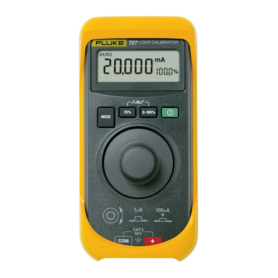
Fluke 707 Instruction Sheet
Loop calibrator
Hide thumbs
Also See for 707:
- Specifications (1 page) ,
- Application note (8 pages) ,
- Calibration information manual (10 pages)
Advertisement
Table of Contents
- 1 Battery Saver
- 2 Warnings and Cautions
- 3 Pushbutton Functions
- 4 Using the Ma Sourcing (Output) Modes
- 5 Changing the Ma Output Span
- 6 Contacting Fluke
- 7 Simulating a Transmitter
- 8 Auto Ramping the Ma Output
- 9 Using the Spancheck Function
- 10 Measuring DC Ma with Loop Power
- 11 Measuring DC Volts
- 12 Maintenance
- 13 Replacing the Battery
- 14 Replaceable Parts
- 15 Accuracy Specifications
- 16 General Specifications
- Download this manual
Introduction
The Fluke 707 Loop Calibrator (hereafter, the Calibrator) is a
compact sourcing and measuring tool. The Calibrator tests current
loops of 0-20 mA or 4-20 mA and measures dc voltage to 28 V. It
comes with a set of alligator-clip test leads, a 9 V alkaline battery,
and this Instruction Sheet.
The Calibrator is a IEC 61010, CAT I 30 V, Pollution Degree 2
instrument. A CAT I instrument is designed to protect against
transients from high-voltage, low-energy sources, like electronic
circuits or a copy machine, for example.
Function
Measure V dc
Measure mA dc
Source mA dc
Source loop power
Battery Saver
The Calibrator automatically turns off after 30 minutes of inactivity.
To reduce this time or disable this feature:
1.
With the Calibrator OFF, press D.
PSXX is displayed, where XX is the turn-off time in minutes.
OFF means the power saver is disabled.
2.
Turn m to decrease or increase the turn-off time.
To disable, turn m until the display shows OFF.
3.
The Calibrator resumes normal operation after 2 seconds.
August 2001 (English) Rev. 2, 2/08
© 2001-2008 Fluke Corporation. Product specifications are subject to
change without notice. All rights reserved.
Calibrator Capabilities
Range
28 V
0 to 24 mA
24 V dc
Loop Calibrator
Instruction Sheet
Resolution
1 mV
1 A
N/A
®
707
Advertisement
Table of Contents

Subscribe to Our Youtube Channel
Related Manuals for Fluke 707


Summary of Contents for Fluke 707
-
Page 1: Battery Saver
Loop Calibrator Instruction Sheet Introduction The Fluke 707 Loop Calibrator (hereafter, the Calibrator) is a compact sourcing and measuring tool. The Calibrator tests current loops of 0-20 mA or 4-20 mA and measures dc voltage to 28 V. It comes with a set of alligator-clip test leads, a 9 V alkaline battery, and this Instruction Sheet. -
Page 2: Warnings And Cautions
Caution: Static discharge can damage parts Double insulated Battery Conforms to relevant Canadian Standards Association directives. Certification # LR110460-2. Conforms to European Union requirements Direct current Do not dispose of this product as unsorted municipal waste. Go to Fluke’s web site for recycling information. -
Page 3: Pushbutton Functions
Pushbutton Functions Pushbutton Function ON or OFF button. and D simultaneously to toggle Press between the mA output spans. 4 mA to 20 mA = 0 % - 100 % (default) (Power-on Option) 0 mA to 20 mA = 0 % - 100 % (optional) The selection is saved until it is changed. -
Page 4: Using The Ma Sourcing (Output) Modes
Using the mA Sourcing (Output) Modes The Calibrator outputs current for calibrating and testing 0 to 20 mA and 4 to 20 mA current loops and instruments. In SOURCE mode, the Calibrator supplies the current. In SIMULATE mode, the Calibrator simulates a 2-wire transmitter in an externally-powered current loop. -
Page 5: Contacting Fluke
Contacting Fluke To contact Fluke for product information, operating assistance, service, or to get the location of the nearest Fluke distributor or service center, call: 1-888-44-FLUKE (1-888-443-5853) in U.S.A 1-800-36-FLUKE in Canada +31-402-675-200 in Europe +81-3-3434-0181 Japan +65-738-5655 Singapore +1-425-446-5500 from other countries Or visit Fluke's web site at: www.fluke.com. -
Page 6: Simulating A Transmitter
Simulating a Transmitter When simulating the operation of a transmitter, the Calibrator regulates the loop current to a known value selected by you. A 12 V to 28 V loop supply must be available. Insert the test leads as shown below. LOOP CALIBRATOR Press simultaneously once for slow ramp... -
Page 7: Auto Ramping The Ma Output
Auto Ramping the mA Output Auto ramping allows you to continuously apply a varying current from the Calibrator to a passive (sourcing) or active (simulate) loop. Your hands remain free to test the transmitter’s response. Press B + C simultaneously to enter the Auto Ramp mode and step to a ramp type. - Page 8 Measuring dc mA W Caution To prevent damage to the unit under test, ensure that the Calibrator is in the correct mode before connecting the test leads. To measure dc mA: Press A to step to MEASURE mode. MEASURE mA is displayed. Touch test lead probes to the circuit across the load or power source as shown below.
-
Page 9: Measuring Dc Ma With Loop Power
Measuring dc mA with Loop Power W Caution To prevent damage to the unit under test, ensure that the Calibrator is in the correct mode before connecting the test leads. Loop power provides 24 V to power a transmitter and to read loop current simultaneously. -
Page 10: Measuring Dc Volts
Measuring dc Volts W Caution To prevent damage to the unit under test, ensure that the Calibrator is in the correct mode before connecting the test leads. To measure dc Volts: Press A to step to MEASURE mode. MEASURE V is displayed. Touch test lead probes across the load or power source. -
Page 11: Maintenance
Remove any input signals prior to removing test leads and opening case. When servicing the Calibrator, use only specified replacement parts. Do not allow water to get in the case. For maintenance procedures not described in this Instruction Sheet, contact a Fluke Service Center. - Page 12 Instruction Sheet. Check the battery and test leads. Replace as needed. Contact a Fluke Service Center if the Calibrator needs repair or does not seem to be operating properly. If the Calibrator is under warranty, refer to the warranty statement for warranty terms, conditions, and product return information.
-
Page 13: Replacing The Battery
Replacing the Battery W Warning To avoid false readings, which could lead to electric shock or injury, replace the battery as soon as M (low battery indicator) appears on the display. Use only a single 9 V battery, properly installed, to power the Calibrator. -
Page 14: Replaceable Parts
Replaceable Parts ADA10F.EPS Item Description Part No. Qty. Rotary knob 1618022 Case top 1618355 Keypad 1612222 Case bottom 1618005 Non-skid foot 885884 Battery. 9 V, Alkaline, ANSI / NEDA 614487 1604A or IEC 6LR61 Case screws 665098 Battery door 665106 CD ROM 2088974 Test lead set... -
Page 15: Accuracy Specifications
Accuracy Specifications Accuracy is specified for 1 year after calibration at operating temperatures of 18 C to 28 C and is given as: ( [ % of reading ]+[ counts ] ) MEASURE V dc Range: 28 V ( 30 V max) Resolution: 1 mV Input Impedance: 1 M Accuracy: (0.015 % of reading+2 counts) -
Page 16: General Specifications
General Specifications Maximum voltage between any terminal and earth ground or between any two terminals: 30 V Storage temperature: -40 C to 60 C Operating temperature: -10 C to 55 C Operating altitude: 3000 meters maximum Temperature coefficient: 0.005 % of range per C for temperatures of -10 C to 18 C and 28 C to 55 C Relative humidity: 95 % up to 30 C;...
Need help?
Do you have a question about the 707 and is the answer not in the manual?
Questions and answers