Advertisement
Quick Links
Advertisement

Related Manuals for MshOt MI-BGU-LED-TS100


Summary of Contents for MshOt MI-BGU-LED-TS100
- Page 1 MI-BGU-LED-TS100 LED Fluorescence Illuminator User Manual...
- Page 2 MI-BGU-LED-TS100 LED fluorescence illuminator...
- Page 3 Thank you for buying our product! This unit is a precision optical instrument. Our product has been design to provide the highest level of safety, however, improper operation or negligence in following the instructions in this manual may cause personal injuries and property losses. In order to ensure your safety, prolong the life of this unit and maintain it properly, please read this manual carefully before operating this unit.
- Page 4 Content Ⅰ. Introduction ........................1 Ⅱ. Main specification ......................2 Ⅲ. Components and functions ...................2 Ⅳ. Installation ......................... 2~4 Ⅴ. Operation ........................4~5...
- Page 5 Ⅰ. Instruction The MSHOT MI-LED series LED fluorescence attachment takes us of long working life LED as light source, can easily expand Nikon TS-100 microscope into an energy-saving, efficient, easy to operate and super long-life LED lighting fluorescence microscope and do not effect original bright field observation.
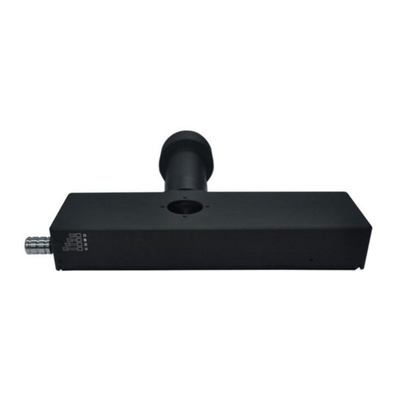
- Page 6 Ⅲ. Components and functions 1. LED module:containing fluorescence filter cubes, filters, lever used to exchange colors. 2. Light source:LED light source has different wavelength LED lamps. 3. Fixed sheet metal: used to connect and fix LED module to the microscope. 4.
- Page 7 2.Take out the fixed metal plate of the fluorescent module, place it in the installation area of TS100 microscope module after disassembly, and fix it with fixing screws (as shown in Fig. 02). Figure 02 3.Place the main body of the excitation block of the fluorescent module into the module installation area of the fixed metal plate from the side (as shown in Fig.
-
Page 8: Ⅴ.installation
6. Connecting the light source: connect the light source illuminator with the lens fixing cylinder from the rear end of the microscope, and lock the two hexagon socket fixing screws on the lens fixing cylinder, as shown in Fig. 05 Figure 06 7. - Page 9 2.Select the lighting source you want on the light illuminator. If you need UV lighting, select UV (as shown in Figure 09). Figure 09 3.According to the diagram on the LED module, pull the pull rod to switch the fluorescent excitation block to the band matching the light source.
- Page 10 5. In the installation process, pay attention to the smoothness of the module position, otherwise the uniformity of the light may become worse. This power supply must strictly use the special adapter of 12V 2A, and the customer who uses other adapters shall be responsible for the equipment damage.
Need help?
Do you have a question about the MI-BGU-LED-TS100 and is the answer not in the manual?
Questions and answers