
Related Manuals for phytron phyMOTION I1AM01.2


Summary of Contents for phytron phyMOTION I1AM01.2
- Page 1 1 Axis Stepper Motor Drive I1AM01.2 / I1AM0a.2 Firmware Version: V1.1.2 (Loader) V1.1.2 (Loader) V1.1.6 (System) V1.1.6 (System) TRANSLATION OF THE GERMAN ORIGINAL MANUAL 10/2015 Manual MA 1269-A007 EN...
- Page 2 We appreciate suggestions and criticisms for further improvement. Email address: doku@phytron.de Questions about the use of the product described in the manual that you cannot find answered here, please contact your representative of Phytron (http://www.phytron.de/) in your local agencies. MA 1269-A007 EN...
-
Page 3: Legal Information
1 Legal Information This manual: Read this manual very carefully before mounting, installing and operating the device and if necessary further manuals related to this product. Please pay special attention to instructions that are marked as follows: DANGER –... - Page 4 Manual I1AM01 / I1AM0a Qualified personnel WARNING – Serious injury possible! Serious personal injury or serious damage to the machine and drives could be caused by insufficiently trained personnel! Without proper training and qualifications damage to devices and injury might result! - Design, installation and operation of systems may only be performed by qualified and trained personnel.
- Page 5 WARNING – Serious injury from electric shock! If the phyMOTION is not operated with SELV/PELV voltages, the risk of dangerous voltages may be on the device. Touching these components carrying high voltages can cause serious injury or death from electric shock: - Always observe the safety concept SELV / PELV to ensure safe isolation and separation of low voltage supplies from the mains.
-
Page 6: Table Of Contents
Manual I1AM01 / I1AM0a 2 Contents 1 Legal Information ...................... 3 2 Contents ........................6 3 I1AM01/I1AM0a Module Overview ................7 4 Technical Data ......................9 4.1 Declaration of Conformity ..................9 4.2 Mechanical Data ....................11 4.3 Features ....................... 12 4.4 Functions ...................... -
Page 7: I1Am01/I1Am0A Module Overview
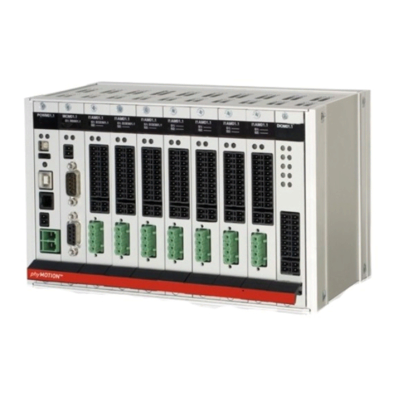
3 I1AM01/I1AM0a Module Overview I1AM01/I1AM0a stands for “1 Axis Indexer with Integrated Power Stage (amplifier)”. This module is a full stepper motor drive up to 3.5 A max. It can be connected directly next PEAK to a MCM (main controller module). The module includes a mid-performance indexer and a mid-performance power stage. - Page 8 Manual I1AM01 / I1AM0a Ordering code of the 1 axis stepper motor drive module (I1AM01/I1AM0a): Ordering code (example): I1AM01-ECES01-PTS01: 1 axis stepper motor drive module with integrated encoder and PT sensor MA 1269-A007 EN...
-
Page 9: Technical Data
4 Technical Data 4.1 Declaration of Conformity MA 1269-A007 EN... - Page 10 Manual I1AM01 / I1AM0a MA 1269-A007 EN...
-
Page 11: Mechanical Data
4.2 Mechanical Data Dimensions 100 x 100 mm (without front panel) Weight 109 g / 124 g (without / with font panel) Mounting Plug-in module into the modular stepper motor controller phyMOTION Mounting position Vertical MA 1269-A007 EN... -
Page 12: Features
Manual I1AM01 / I1AM0a 4.3 Features Performance Characteristics Stepper motor Suitable for bipolar control of 2 phase stepper motors with 4, (6) or 8 lead wiring Superior controller Modular phyMOTION controller Supply voltage 24…48 V Nominal voltage: 48 V internal Phase current 0.1 to 3.5 A PEAK... - Page 13 - Resolver or LVDT/RVDT (needs ECMS01) Communication via Proprietary phytron bus backplane bus Communication and programming Programming Via phytron‘s programming environment phyLOGIC ToolBox Communication Master-slave communication. The I1AM01/I1AM0a is slave and communicates with the MCM main controller module. MA 1269-A007 EN...
-
Page 14: Functions
Manual I1AM01 / I1AM0a 4.4 Functions Integrated stepper motor indexer for standard functions • Relative and absolute positioning • Reference movements/ speed mode • Step frequency up to 40,000 steps/sec. Integrated 3.5 A power stage PEAK • Integrated 3.5 A / 24 to 48 V stepper motor power stage PEAK... -
Page 15: Installation
5 Installation Phytron always delivers the phyMOTION™ completely assembled in order to make sure you can start with the installation and the wiring right away. Further manual Detailed information on this subject is in a supporting manual: “phyMOTION Modular Multi-axis Controller for Stepper Motors”... - Page 16 Manual I1AM01 / I1AM0a Before integrating or switching modules always make sure that the phyMOTION™ is shut down and the power supplies are disconnected. WARNING – Serious injury from electric shock! During electrical installation cables, connectors, etc. can be live. - Before starting wiring, make sure that none of the power supplies are connected to the primary side of the mains supply.
-
Page 17: Electrical Installation
5.2 Electrical Installation Ensure sufficient bending radius of the cables during installation. Do not lay the cables in tension or bend them. We recommend labelling the mating connectors to prevent interchanging the connectors. If all the connections are made, the last step is to plug in the power supply to the mains. -
Page 18: Pin Assignment
Manual I1AM01 / I1AM0a 5.2.2 Pin Assignment In the following the pin assignment: Fig. 2: Pin assignment Use the specified mating connectors for wiring. CAUTION – Possible damage! Damage of the module by wrong connection. - Do not exchange the 10-pin connector for limit switches with the 10-pin connector for the encoder evaluation. -
Page 19: Stepper Motor Connection
5.2.3 Stepper Motor Connection In the next chapter the connection of a 2 phase stepper motor with 4, (6), or 8 lead wiring is described. Stepper motors with 0.1 to 3.5 A can be controlled at maximum 48 V... - Page 20 Manual I1AM01 / I1AM0a Stepper motors with 8 leads can be connected with the windings wired in parallel (1) or series (2). For 6 lead stepper motors, wiring scheme (3) with series windings is recommended. If wiring scheme (3) cannot be used because of the motor construction, the motor may be operated with only two of the four windings energized according to wiring scheme (4).
-
Page 21: Limit Switch Connection
5.2.4 Limit Switch Connection Fig. 4: Pin assignment of the limit switches Fig. 5: Input wiring The controller is designed for connection of up to three limit switches type PNP-NOC/NCC. A limit switch is determined for monitoring the movement in the + direction (limit switch +), the second in the –... -
Page 22: Option: Encoder Connection
Manual I1AM01 / I1AM0a 5.2.5 Option: Encoder Connection Fig. 6: Pin assignment of the encoder Suitable encoder types depend on the selected evaluation module (ECES01/ECAS01): – differential incremental encoder with quadrature signals (ECAS01/ECES01) – Absolute encoder according to the SSI standard (ECAS01/ECES01) –... - Page 23 Wiring of the encoder Fig. 7: Wiring: SSI/Quadrature Fig. 8: Wiring: EnDat encoder MA 1269-A007 EN...
- Page 24 Manual I1AM01 / I1AM0a Optional accessories: adapter cable for EnDat encoder Fig. 9: Adapter cable (ID no 10014905) MA 1269-A007 EN...
-
Page 25: Option: Resolver, Lvdt Or Rvdt Connection
5.2.6 Option: Resolver, LVDT or RVDT Connection Characteristics - Excitation amplitude: 5 to 10 V r.m.s - Excitation frequency: 10 kHz - Excitation current: up to 150 mA - Resolution: up to 8 arcmin (8/4096 increments/rev.) Fig. 10: Pin assignment of the encoder connector... - Page 26 Manual I1AM01 / I1AM0a Operating modes of the encoders Resolver Fig. 11: Resolver wiring 4-wire-LVDT Fig. 12: 4-wire-LVDT/RVDT wiring (full bridge) MA 1269-A007 EN...
- Page 27 Fig. 13: 4-wire-LVDT/RVDT-wiring (half bridge) 5/6-wire-LVDT Fig. 14: 5-wire-LVDT/RVDT-wiring MA 1269-A007 EN...
- Page 28 Manual I1AM01 / I1AM0a Fig. 15: 6-wire-LVDT/RVDT-wiring MA 1269-A007 EN...
-
Page 29: Option: Motor Temperature Sensor Connection
Depending on the selected evaluation module (KTS01 or PTS01) thermal elements type K or platinum sensors PT100 can be used. The insulated temperature sensor in phytron motors is integrated in the motor windings. The response time is very short, compared to temperature sensors mounted outside the motor housing. - Page 30 Manual I1AM01 / I1AM0a An accurate temperature can only be measured when the temperature at the reference junction (connector) is exactly known. This is not possible by the connection construction and und can cause indeterminate deviations of the temperature values. Software evaluation of the measuring values from -180 °C to +260 °C.
-
Page 31: Commissioning
6 Commissioning Please read the manual for basic commissioning information of the I1AM01/I1AM0a module: Further manual Detailed information on this subject is in a supporting manual: “phyMOTION Modular Multi-axis Controller for Stepper Motors” The programming environment phyLOGIC ToolBox is explained in the following manual:... -
Page 32: Diagnostics By The Leds
Manual I1AM01 / I1AM0a 6.1 Diagnostics by the LEDs The LEDs indicate the status and error of the I1AM01/I1AM0a module by colours and blinking: Status of the I1AM left right ready and power stage is green green activated ready and power stage is green NOT activated motor is running... -
Page 33: Parameterising The Modules
6.2 Parameterising the Modules When using encoders, the corresponding phyLOGIC parameters P34 to P39 should be checked and set. For the power stage settings use the parameters P43 to P45. For a general overview of the parameters: Further manual Detailed information on this subject is in a supporting manual: “phyLOGIC... -
Page 34: Principles Of Positioning
Manual I1AM01 / I1AM0a 7 Principles of Positioning Further manual Detailed information on this subject is in a supporting manual: “Principles of Positioning of the Stepper Motor Controllers“ A change of the frequency and target position during positioning is ignored and is only possible during the free run. -
Page 35: Service
- If you want to use the phyMOTION™ after removing a module, the gap has to be sealed with a blanking plate before power supply is reconnected and switched on. - To send a module to phytron use ESD packaging only. MA 1269-A007 EN... -
Page 36: Warranty, Disclaimer And Registered Trademarks
9 Warranty, Disclaimer and Registered Trademarks Disclaimer Phytron GmbH has verified the contents of the manual to match with the hardware and software. However, errors and omissions are exempt and Phytron GmbH assumes no responsibility for complete compliance. The information contained in this publication is reviewed regularly and any necessary corrections are included in subsequent editions. -
Page 37: Index
Index Motor connection 19 Motor time constant 20 Cable 12 Change of frequency 34 Copyright 2 Nominal voltage 12 Current consumption 12 Outputs 13 Error detection 13 Parameterisation 13 Functions 14 Platinsonde 30 Programming 13 Inductance 20 Inputs 13...
Need help?
Do you have a question about the phyMOTION I1AM01.2 and is the answer not in the manual?
Questions and answers