
Related Manuals for phytron TM StepDrive 1x24..48V/5A


Summary of Contents for phytron TM StepDrive 1x24..48V/5A
- Page 1 TM StepDrive 1x24..48V/5A Stepper Motor Module for the SIMATIC ET 200 ® ® Manual 1303-A007 EN Extreme. Precision. Positioning.
- Page 2 TM StepDrive 1x24..48V/5A ® ® for SIMATIC ET 200 Module Description and Commissioning TRANSLATION OF THE GERMAN ORIGINAL MANUAL 04/2021 Manual MA 1303-A007 EN...
- Page 3 ® n this manual, you will find the feature descriptions and specifications of the ET 200 module for positioning of a stepper motor: TM StepDrive 1x24..48V/5A (phytron 10020273). This manual is supplementary to the SIMATIC ET 200SP Distributed I/O system.
- Page 4 Questions about the use of the product described in the manual that you cannot find an- swered here, please contact your representative of Phytron (http://www.phytron.de/) in your local agencies. Further manuals All current manuals for SIMATIC products are available for free download on the Internet: (https://support.industry.siemens.com/cs/start?lc=en-DE)
-
Page 5: Table Of Contents
Technology Module TM StepDrive 1x24..48V/5A Content 1 TM StepDrive 1x24..48V/5A ......6 6.3 Operating Modes of the StepDrive Technology Module ....... 36 1.1 Short Overview ........6 6.4 Potential Group ........36 1.2 Overview of the most important features of the StepDrive technology module: ... - Page 6 8.2 Run Commands ........62 11 Warranty and Trade Marks ....... 78 8.2.1 Moving to Absolute Position ....62 12 Appendix: Parameters and Data Record ... 79 8.2.2 Moving a Relative Distance ....62 12.1 Data Record 128 (DS128): Read and Write Parameters ........
-
Page 7: Tm Stepdrive 1X24
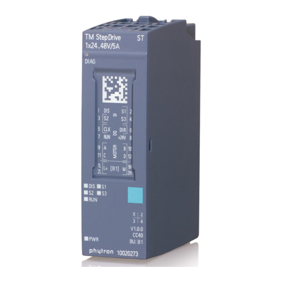
1 TM StepDrive 1x24..48V/5A 1.1 Short Overview Fig. 1: The TM StepDrive technology module The TM StepDrive 1x24..48V/5A technology module is a stepper motor controller with in- tegrated power stage. It is specially developed for application in the decentralised SIMAT- ® ®... -
Page 8: Overview Of The Most Important Features Of The Stepdrive Technology Module
1.2 Overview of the most important features of the StepDrive technology module: 2-phase stepper motor controller with integrated power stage for SIMATIC ® ® 200 W power range up to 5 A at 24 to 48 V PEAK ... -
Page 9: Overview Of The Data Interfaces
Technology Module TM StepDrive 1x24..48V/5A 1.3 Overview of the Data Interfaces ® Configuration transfer: Configuration of the module with STEP 7: all parameters of the TM StepDrive technology module can be set by mouse click and transmitted. See chap. 6.5... -
Page 10: Directives And Standards
1.4 Directives and Standards CE Mark With the declaration of conformity and the CE Mark on the product, the manufacturer certifies that the product complies with the requirements of the relevant EC directives. The unit, described here, can be used anywhere in the world. -
Page 11: Declaration Of Conformity
Technology Module TM StepDrive 1x24..48V/5A 1.5 Declaration of Conformity MA 1303-A007 EN... -
Page 12: To Consider Before Installation
2 To Consider Before Installation Read this manual very carefully before installing and operating the TM StepDrive. Observe the safety instructions in the following chapter! 2.1 Qualified Personnel Design, installation and operation of systems using the TM StepDrive may only be performed by qualified and trained personnel. - Page 13 Technology Module TM StepDrive 1x24..48V/5A Malfunctions are possible while programming the instruction codes – e.g. sudden running of a connected motor, braking etc. Please test the program flow step by step! Each end user system is customised and differs from the testing platform.
-
Page 14: Ambient Conditions
The DIS input is not a safety-operating mode according to IEC61800-5-2 such as "Safe Torque Off" (ST0) by pulse pattern inhibition. 2.3 Ambient Conditions Operating temperature 0 °C to +60 °C Storage and transport - 40 °C to +70 °C... -
Page 15: Safety Concept
Technology Module TM StepDrive 1x24..48V/5A 3 Safety Concept 3.1 Safety Measures The following measures are vital to the safety of the system. Carry out the safety measures with particular care and adapt them to meet the requirements of the system. -
Page 16: Emc Measures
Preset for EMC: Motor cable The motor cable is a source of interference and must be positioned carefully. Use the cables recommended by Phytron. They are tested for EMC safety and are suita- ble for movement. The shield of the motor cable must be connected to the BaseUnit and to the motor with low impedance or flat. -
Page 17: Shielding
A common-mode rejection filter should be used with motor cable lengths >5 m and a current setting >50 % of the rated current of the TM StepDrive. In addition to the use of Phytron filters, other possibly central measures can also contribute to compliance with the EMC requirements. -
Page 18: Technical Data
4 Technical Data 4.1 Mechanical Data ® ® Type SIMATIC ET 200 SP plastic housing Dimensions 20 x 73 x 58 mm (W x H x D) Weight about 62 g ® ® Mounting Pluggable in SIMATIC ET 200 SP system with connections ®... -
Page 19: Features
Technology Module TM StepDrive 1x24..48V/5A 4.2 Features Features Stepper motors Suitable for bipolar control of 2-phase stepper motors with 4, (6) or 8 lead wiring ® ® Superior main station SIMATIC ET 200 Power supply 24 to 48 V Nominal voltage: 48 V... - Page 20 DIAG Diagnostic LEDs DIS (power stage disabled) S1 (switch 1 is active) S2 ((switch 2 is active) S3 ((switch 3 is active) RUN (motor is running) PWR (load voltage is present) moving to absolute position...
- Page 21 Technology Module TM StepDrive 1x24..48V/5A Interfaces Analogue outputs A, B, C, D for a 2-phase stepper motor Digital inputs 3 configurable digital inputs S1, S2 and S3: 0 signal: 0 ... 1 V with max. 2 mA 1 signal: 2.3 V ... 30 V with typ. 5 mA...
- Page 22 Control interface Specifications in positioning mode: Target position with absolute positioning Number of steps for relative positioning Frequency at free run Offset during reference run Use of the reference sensor during reference travel Traversing job...
- Page 23 Technology Module TM StepDrive 1x24..48V/5A Feedback interface Configurable in positioning mode: residual distance velocity Also included in the feedback: absolute position status bits o motor is running o ready for new run command o parameterisation error...
- Page 24 Data record transfer to Diagnostics the TM StepDrive Feedback of the following driver parameters(asynchronous) (asynchronous) to the main station: read back the power stage parameters error (overtemperature, parameterisation error, DIS in- put) MA 1303-A007 EN...
-
Page 25: Installation
24 to 48 V supply BaseUnit type B1 BU20-P12+A0+4B (Siemens article number 6ES7-193-6BP20- 0BB1) TM StepDrive 1x24..48V/5A (Phytron order number 10020273) 2-phase stepper motor up to 5 A PEAK the necessary wiring material MA 1303-A007 EN... -
Page 26: Sizing Of The Power Supply
5.1 Sizing of the Power Supply The voltage of the supply unit (24 V or 48 V ) depends on the motor speed during op- eration. For low velocity (about < 300 rev/min) but high torque or if only low torque is nec- essary at higher velocity (>... -
Page 27: Mechanical Installation
Technology Module TM StepDrive 1x24..48V/5A 5.2 Mechanical Installation See chap. 3 of the SIMATIC ET 200SP BaseUnits technical manual. You can mount the ET 200SP decentralised peripheral system in any mounting position. The preferred installation position is horizontal mounting on a vertical wall. Restrictions of the ambient temperature are possible in certain installation positions. -
Page 28: Temperature Behaviour Of The Tm Stepdrive Under Typical Operating Conditions
5.3 Temperature Behaviour of the TM StepDrive under Typical Operat- ing Conditions The adjusting module temperature depends on the motor type, the motor cable length, phase current, supply voltage and the tolerance of the compo- nents. In practice, it can differ from the diagrams below. -
Page 29: Electrical Installation
Technology Module TM StepDrive 1x24..48V/5A 5.4 Electrical Installation Two different connection types define the function of the TM StepDrive module: 5.4.1 Connection Type “Power stage“ Connect the motor voltage (24 to 48 V ) to terminals L+ and M ... -
Page 30: Connection Type "Indexer
5.4.2 Connection Type “Indexer“ IMPORTANT Malfunction due to missing I/O input voltage! If the motor voltage is applied to L+ and M terminals, the indexer is in operation. However, the indexer only outputs signals when the 24 V input voltage is ap- plied to the I/O input. -
Page 31: Motor Connection
Technology Module TM StepDrive 1x24..48V/5A The logic is supplied for both connection types. The limit switches and external output stage are optional. Further manual For connecting the TM StepDrive to the BaseUnit, refer to the instructions in the following manual: SIMATIC ET 200SP Distributed I/O system, A5E03576849-AH https://support.industry.siemens.com/cs/document/58649293/simatic-et-200sp-... - Page 32 Motor time constant applies to the motor´s electrical time constant The total inductance L is equal to the winding inductance in a parallel circuit, be- total cause of shared inductances. = 4 x L applies to a series circuit.
-
Page 33: Wiring Schemes
Technology Module TM StepDrive 1x24..48V/5A 5.5 Wiring Schemes Fig. 9: Connection diagrams for 4-, (6-) and 8- wire stepper motors MA 1303-A007 EN... -
Page 34: Diagnostics By The Leds
5.6 Diagnostics by the LEDs The LEDs indicate the status and error of the power stage of the TM StepDrive module by colour: Colour Meaning DIAG The backplane bus supply of the ® ET 200 SP is not OK. -
Page 35: Commissioning
Technology Module TM StepDrive 1x24..48V/5A 6 Commissioning ® You begin by adapting the hardware configuration to your existing ET 200 SP-Station. This is possible with PROFIBUS Master or with STEP 7 (TIA Portal ) from V15 or via GSD ®... -
Page 36: Configuration Of The Module Using The Gsd Description File
6.2 Configuration of the Module Using the GSD Description File The resolution of the current settings is reduced, because in the GSD format only a small amount of data is available on the PROFIBUS. The resulting current is shown in the following table:... -
Page 37: Operating Modes Of The Stepdrive Technology Module
Technology Module TM StepDrive 1x24..48V/5A 6.3 Operating Modes of the StepDrive Technology Module The task of the TM StepDrive is the positioning of a stepper motor to certain specified tar- gets (positioning mode (PM mode)) and endless travel at defined frequencies (frequency mode (TO mode)). -
Page 38: Configuration Of The Module
6.5 Configuration of the Module 6.5.1 Basic Parameters 6.5.1.1 Operating Mode Selecting an operating mode: Positioning or positioning mode (PM mode) Control via technology object (TO mode) 6.5.1.2 Connection Type Selecting a connection type: “Power stage“: The TM-StepDrive uses the integrated power stage to supply a stepper motor. - Page 39 Technology Module TM StepDrive 1x24..48V/5A 6.5.1.3 Start Description of the function The parameter activates or deactivates the internal power stage (the motor is energised or de-energised). Movement of a motor connected to the power stage is only possible with activa- tion! .An external power stage connected to the outputs CLK / DIR is supplied with clock and...
-
Page 40: Diagnosis
6.5.2 Diagnosis The module monitoring is always active. A detected error only triggers a diagnostic alarm if the diagnostic type is activated in the diagnostic check boxes. Diagnosis type TM StepDrive module error Standard Diagnosis option message missing supply... -
Page 41: Indexer Configuration
Technology Module TM StepDrive 1x24..48V/5A – The CPU changes to STOP and interrupts the program processing. The di- agnostic alarm OB (e.g. OB 82) is activated. The action that triggered the alarm is written to the start information of the diagnostic alarm OB. - Page 42 6.5.3.2 Run Frequency (only for PM Mode) This frequency is used for positioning and for free run. Value can be set from 1 Hz to 250 kHz 6.5.3.3 Reference Frequency (only for TO Mode) In TO mode, the run frequency is set relative to the reference frequency. Permitted value range is -200% to +200% of the reference frequency.
- Page 43 Technology Module TM StepDrive 1x24..48V/5A 6.5.3.6 Traversing Range (in PM mode only) The value determines whether it is a rotating axis or a linear axis. For a rotating axis, a zero is set here, i.e. the movement of the axis is not restricted. (0--> rotation axis) With a linear axis, the maximum traverse range can be set here, which activates a limita- tion of the axis by software.
-
Page 44: Inputs
6.5.4 Inputs The function of the inputs differs depending on the operating mode: 6.5.4.1 Operating Mode Positioning (PM mode) The three parameters "Function input S1/2/3" each link one input to its logic function. Each input can be used as left limit switch, right limit switch, reference switch or remain unused. - Page 45 Technology Module TM StepDrive 1x24..48V/5A 6.5.4.3 Normally Closed (NC) or Normally Open Contact (NO) Input S1/2/3 can be used for opening and closing switches. If the input is used, its status will be indicated by LED S1/2/3. The LED shines, when the input is active, i.e. depending on the switch type, the LED shines, when a normally closed contact has opened or when a normally open contact has closed.
-
Page 46: Power Stage Configuration
6.5.5 Power Stage Configuration 6.5.5.1 Step Resolution With a 2-phase stepper motor operating in the full step mode, the exact physical resolution of the motor is reached. For a 200 step motor that means an obtainable resolution of 200 steps per revolution at the motor shaft. - Page 47 Technology Module TM StepDrive 1x24..48V/5A 6.5.5.2 Run Current Here, the motor current during run is defined. Value adjustable (in 100 mA increments): 0 = not allowed 1 = 0.1 A r.m.s. 35 = 3.5 A r.m.s. 6.5.5.3 Stop Current Here, the motor current is defined, to which is switched after the lapse of the current delay time as soon as the motor is stopped.
- Page 48 10: 40 ms 11: 60 ms 12: 100 ms 13: 200 ms 14: 500 ms 15: 1000 ms 6.5.5.6 Boost at Acceleration (in PM Mode Only) If the parameter is set to one, a different current is used during acceleration and braking than for movement with constant frequency.
-
Page 49: I/O Addresses
Technology Module TM StepDrive 1x24..48V/5A 6.5.6 I/O Addresses You can assign the base addresses for the control and feedback interfaces. Your program logic uses the values stored in these addresses to control the TM StepDrive output and to read the feedback signals from the module. -
Page 50: Configuration Of The Module Via Tia Portal
Clock synchronous operation The checkbox for clock-synchronous operation is only displayed, if the system hardware supports clock-synchronous operation. ® 6.6 Configuration of the Module via TIA Portal ® You begin by adapting the hardware configuration to your existing ET 200 SP station. - Page 51 Technology Module TM StepDrive 1x24..48V/5A MA 1303-A007 EN...
-
Page 52: Parameterising Of The Module Via Tia Portal
® 6.7 Parameterising of the Module via TIA Portal ® The next step sets the parameters for the TM StepDrive with TIA Portal MA 1303-A007 EN... -
Page 53: Parameter (Ds128)
Technology Module TM StepDrive 1x24..48V/5A 6.7.1 Parameter (DS128) Introductory remarks When the system is switched on, the configured parameters are transferred from the CPU to the module via DS128. The parameters can be changed during operation by the user program (see chap. 12). -
Page 54: Program Control And Feedback Interface
7 Program Control and Feedback Interface Data is written from the CPU to the module and data from the module is read out by the CPU (optionally synchronous) via the control and feedback interface. Fig. 10: Data interfaces MA 1303-A007 EN... -
Page 55: Control Interface In The Pm Mode
Technology Module TM StepDrive 1x24..48V/5A 7.1 Control Interface in the PM mode The control interface is shown in a table in chapter 13. The address data in the example refer to a configuration in which the module has been assigned input addresses from 0 to 7.1.1 Control Value... -
Page 56: Feedback Mode Setting
7.1.3 Feedback Mode Setting This determines ((data type 8 Bit, DEZ, address QB5) which value is transmitted as a feedback value in the feedback interface: 0. no response value 1. distance remaining (only for positioning) 2. current frequency 7.1.4 Error Reset The parameter (data type single bit, BOOL, address Q6.6) causes the module to delete... -
Page 57: Feedback Value
Technology Module TM StepDrive 1x24..48V/5A 7.2.2 Feedback Value Depending on the setting in byte 5 of the control interface, either nothing is displayed here or the remaining distance to be travelled or the current frequency is displayed when posi- tioning (data type 32 Bit, DEZ+/-, address ID4). - Page 58 Name Meaning I10.0 Rotation is set, if the motor rotates in negative direction. I10.2 Hardware is set, when an input parameterised as a limit switch be- limit switch comes active for a traversing job. active I10.3 Software is set, when, for a traversing job, the distance is exceeded limit switch via the parameterised value of the distance limitation.
-
Page 59: Data Record Transfer
Technology Module TM StepDrive 1x24..48V/5A Name Meaning I11.4 Invalid con- is set if an invalid control value is set in the control data, trol value e.g. too high a frequency for free run. I11.5 Invalid OP is set if an invalid value for the motion command is set in mode the control data. -
Page 60: Operation Of The Tm Stepdrive As A Positioning Controller (Pm Mode)
8 Operation of the TM StepDrive as a positioning controller (PM mode) One of the TM StepDrive tasks is the positioning of a stepper motor to certain specified targets. Driving in positioning mode (PM mode) is explained in more detail in the following chapters. - Page 61 Technology Module TM StepDrive 1x24..48V/5A Fig. 11: Traversing curve of the TM StepDrive for positioning = run frequency = systemic, maximum stepper motor frequency Run frequency / velocity f The run frequency can be set differently for each drive (DS128).
- Page 62 The maximum Frequency f can be estimated from the corresponding characteristic permissible curve. Please note that a sufficiently large safety margin must be applied. Fig. 12: Torque Characteristic Curve of a Stepper Motor Acceleration / deceleration a The maximum permitted acceleration / deceleration depends on the load to be moved. The motor must reach a torque high enough to accelerate or deceleration the load without loss of step.
-
Page 63: Run Commands
Technology Module TM StepDrive 1x24..48V/5A 8.2 Run Commands This chapter explains the permitted modes of operation during positioning: 8.2.1 Moving to Absolute Position Description of the function The absolute mode is used to move the stepper motor to a defined position and thus ap- proach a specified position. -
Page 64: Search For Reference
Traversing job for relative positioning The traversing job contains the following information: Control value = distance (number of pulses o be executed) Run command = 2 If the "Travel range" parameter has a value other than zero, the TM StepDrive checks the specified travel distance for the parameterised limit values ("Travel... - Page 65 Technology Module TM StepDrive 1x24..48V/5A The "Referencing with Offset" bit causes the absolute control value to be ap- proached as an offset at the end of the reference search. The "Referencing to reference sensor" bit causes the reference sensor input to be evaluated.
- Page 66 "Referencing with Offset" = 0 and "Referencing to reference sensor" = 1 Fig. 15: Reference point approach, M0P reference sensor "Referencing with Offset" = 1 and "Referencing to reference sensor" = 1 in pos. di- rection, start position is to the right of the reference signal Fig.
-
Page 67: Free Run With Variable Velocity
Technology Module TM StepDrive 1x24..48V/5A 8.2.4 Free Run with Variable Velocity Description of the function In this mode of operation, the frequency is specified at which the pulses (steps) are to be output. If the frequency is changed, the pulses are output with the new frequency after an acceleration or deceleration phase. -
Page 68: Set Position
Feedback As long as the traversing job is running, this is indicated by the "Motor running" feedback bit set. In addition, the "READY" bit is not set during the traversing job. If a new frequency is set during the acceleration or deceleration phase, the "Ramp" feed- back bit is set;... -
Page 69: Emergency Stop
Technology Module TM StepDrive 1x24..48V/5A 8.2.7 Emergency Stop Description of the function The command terminates running motion commands, absolute and relative positioning is cancelled, and free run is terminated. In contrast to the "Motor stop" run command, the acceleration set by the "acceleration or deceleration” parameter is not used, but a ramp with 10 times the slope. -
Page 70: Stop Conditions
8.3 Stop Conditions 8.3.1 Directed Hold Traversing Job The Hold traversing job is specifically – caused by – indicated by feedback bit STOP by run command 6 or 7 "READY" after stop "Motor running" is removed STOPP by digital input DIS "... -
Page 71: Functions Of The Integrated Power Stage70
Technology Module TM StepDrive 1x24..48V/5A 8.4 Functions of the Integrated Power Stage It is possible to parameterise both the positioning orders and the technology parameters of the integrated power stage. These parameterizations are defined once and not with each traversing job. The parameters of the power unit are transferred in the asynchronous inter- face of the data record transfer. - Page 72 Fig. 19: Traversal curve versus current adjustment at the power stage During the acceleration/deceleration phases, it is automatically switched to the Boost Cur- . According to a time set in the parameter “Run Current Delay Time” t rent I...
-
Page 73: Reaction To Cpu Stop
Technology Module TM StepDrive 1x24..48V/5A 8.4.2 Reaction to CPU STOP The reaction to CPU STOP of the TM StepDrive can be predefined, depending on what is more convenient for the system. Set the reaction to “disable power stage”, if the drive should be without current and there- fore without torque. -
Page 74: Step Resolution
8.4.3 Step Resolution Full step The “full step“ mode is the operating mode in which a 200-step motor, for example, drives 200 steps per revolution. The physical resolution of the motor is achieved in the full step mode. Any further increase of the step resolution (e.g. half step, quarter step, etc.) is done electronically. - Page 75 Technology Module TM StepDrive 1x24..48V/5A Half Step The motor step resolution can be electronically multiplied by 2 by alternately energizing the stepper motor’s phases 1, 1+2, 2 etc. This is the “half step“ mode. The torque, however, is reduced in the half step mode, compared to the full step mode.
- Page 76 Micro Step The step resolution of the TM StepDrive can be increased electronically to 1/256 of a full step. A 200-step motor can, in theory, be commanded to one of 51,200 positions (equal to 0.007° per move pulse) per revolution.
- Page 77 Technology Module TM StepDrive 1x24..48V/5A MA 1303-A007 EN...
-
Page 78: Current Delay Time
Current Delay Time t DELAY so that the motor’s oscillations are decaying after Phytron recommends specifying t DELAY the last motor step and positioning is more accurate. The higher current reduces in this case the decay and incorrect positioning is avoided. -
Page 79: Esd Protective Measures
Our warranty does not cover failures due to incorrect handling. 10 Disclaimer Phytron GmbH has verified the contents of the manual to match with the hardware and software. However, errors and omissions are exempt and Phytron GmbH assumes no re- sponsibility for complete compliance. -
Page 80: Appendix: Parameters And Data Record
12 Appendix: Parameters and Data Record 12.1 Data Record 128 (DS128): Read and Write Parameters The data record can be read without restriction. Bit → Byte ↓ HEADER reserved = 0 MajorVersion = 1 MinorVersion = 0 Length of the following channel parameter block (byte 2 ... 35)34 Byte... - Page 81 Technology Module TM StepDrive 1x24..48V/5A Bit → Byte ↓ PM mode: Run frequency 11…14 TO mode: Reference frequency 15…18 M0P frequency PM mode: Traversing range 19…22 TO mode: reserved Step resolution Current delay time Run current Stop current PM mode: Boost current...
-
Page 82: Data Record 245: Module Parameters Profibus
12.2 Data Record 245: Module Parameters PROFIBUS 12.2.1 Positioning Mode (PM mode) Byte\Bit HEADER reserved = 0 MajorVersion = 1 MinorVersion = 0 Length of the following channel parameter block: byte 2 ... 9 8 byte DRIVER CONFIGURATION / BEHAVIOR DI 2 …... - Page 83 Technology Module TM StepDrive 1x24..48V/5A 12.2.2 Technology Object Mode (TO mode) Bit → Byte ↓ HEADER reserved = 0 MajorVersion = 1 MinorVersion = 0 Length of the following channel parameter block:(byte 2 … 8)7 byte DRIVER CONFIGURATION / BEHAVIOR DI 2 …...
-
Page 84: Appendix: Assignment Of The Control And Feedback Interface
13 Appendix: Assignment of the Control and Feedback Interface 13.1 Assignment of the Control Interface (PM mode) Bit → Byte ↓ 0 … 3 Control value Drive command Feedback operating mode Referen- Referen- Error reserved reserved cing with cing to ref. -
Page 85: Appendix: Error Message And Diagnostic Alarm
Technology Module TM StepDrive 1x24..48V/5A 14 Appendix: Error Message and Diagnostic Alarm 14.1 Error Messages when Writing Data Records If parameterisation errors occur while writing the DS128, an error message is generated: Error Parameter Permissible Setting range 0x20 Acceleration 100 - 100000000... -
Page 86: Diagnosis Notifications
14.2 Diagnosis Notifications Diagnosis Num- Meaning Notification Missing power Missing motor voltage, the module is not supplied via the supply L+ L+ terminal. positioning error An error occurred during positioning. Possible cause can be: a limit switch became active during positioning. -
Page 87: Glossary
Technology Module TM StepDrive 1x24..48V/5A 15 Glossary Term Meaning BaseUnit The BaseUnit carries the StepDrive technology module and represents the contacting for wiring. Boost current Higher motor torque is required for acceleration and decel- eration of a stepper motor compared to the torque at aver- age and slew velocity (f ). - Page 88 Term Meaning GSD file The device database (GSD) describes the characteristics of a device type clearly and completely in an accurate and spe- cific format. The GSD is produced by the equipment manu- facturer for each type of device and is available to the user.
- Page 89 Technology Module TM StepDrive 1x24..48V/5A Term Meaning Backplane bus The backplane bus is a serial data bus over which the TM StepDrive communicates and provides them with the neces- sary voltage. The connection between the modules is via the BaseUnits.
- Page 90 Term Meaning Behaviour at CPU STOP This can be used to configure how the module behaves in the event of CPU failure, cable breakage, etc.: Cancel or continue current positioning, deactivate output stage or set to stop current. MA 1303-A007 EN...
-
Page 91: Index
Technology Module TM StepDrive 1x24..48V/5A 16 Index Micro step 7 Mini step 75 Absolute incremental mode 62 Motor connection 30 Accelaration / deceleration 61 Motor stop 67 Asynchronous 22 Motor time constant 31 Base parameterising 19 Nominal voltage 18 Cable 18... - Page 92 Phytron GmbH Industriestraße 12 – 82194 Gröbenzell T+49-8142-503-0 F +49-8142-503-190 www.phytron.eu...
Need help?
Do you have a question about the TM StepDrive 1x24..48V/5A and is the answer not in the manual?
Questions and answers