Table of Contents
Advertisement
Quick Links
Advertisement
Table of Contents

Subscribe to Our Youtube Channel
Related Manuals for Cormach GEO 15


Summary of Contents for Cormach GEO 15
- Page 1 3D WHEEL ALIGNER GEO 15 Rel. 1 03/19 USE AND MAINTENANCE MANUAL...
-
Page 3: Table Of Contents
TABLE OF CONTENTS INTRODUCTION ��������������������������������������������������������������������������������� 5 TRANSPORT, STORAGE AND HANDLING ������������������������������������������������������ 6 AMBIENT CONDITIONS FOR MACHINE STORAGE �������������������������������������������� 6 INSTALLATION AND SET-UP �������������������������������������������������������������������� 6 AMBIENT CONDITIONS IN THE PLACE OF OPERATION ������������������������������������� 17 ELECTRICAL CONNECTIONS ������������������������������������������������������������������� 18 SAFETY REGULATIONS ������������������������������������������������������������������������� 18 KEY TO CAUTION AND INSTRUCTION LABELS �����������������������������������������������... - Page 4 SAVING AND SEARCH JOBS CARRY OUT ......������������������������� 44 MOST COMMONLY ENCOUNTERED VEHICLE ALIGNMENT FAULTS ������������������������� 51 TROUBLESHOOTING ���������������������������������������������������������������������������� 52 MAINTENANCE ���������������������������������������������������������������������������������� 52 SCRAPPING INFO ������������������������������������������������������������������������������� 53 ENVIRONMENTAL INFORMATION �������������������������������������������������������������� 53 RECOMMENDED FIRE-EXTINGUISHING DEVICES ��������������������������������������������� 54 GLOSSARY ��������������������������������������������������������������������������������������� 54 ELECTRICAL SYSTEM DIAGRAM ��������������������������������������������������������������� 55...
-
Page 5: Introduction
INTRODUCTION WARNING The instructions and information de- The purpose of this manual is to provide scribed in this manual must always be the owner and machine operator with complied with: the producer shall not be effective, safe instructions for the use held responsible for any operation not and maintenance of the aligner�... -
Page 6: Transport, Storage And Handling
TRANSPORT, STORAGE WARNING This operation must be carried out very AND HANDLING carefully to prevent the unit from tipping over or being damaged. Machine transport conditions The aligner must be shipped in its origi- CAUTION nal packaging and stowed in the position Handle with care: violent vibrations may indicated on the outside�... - Page 7 WARNING The machine must not be operated in a potentially explosive atmosphere. CAUTION If the machine is to be installed outdoors, it must be properly sheltered under a roof or any other protection device to avoid contact with water. CAUTION Make sure there are no permanent mag- nets, electromagnets or heat sources near the machine (this might irreparably...
- Page 8 You receive four boxes: • 1 box contains the two cameras and cables; • 1 box contains the two targets and other accessories; • 1 box contains the first upper column and PC holder; • 1 box contains the second lower column. INSTALLATION AREA: Select the right height and distance as illustrated here (for 4 colum lift, please see details A).
- Page 9 Assemble the lower column on the base. Picture 5 Details 1 Bolts kit Mount the upper column on the lower column and fix them by two brackets (Picture 6 and Picture 7 – details 2). Picture 6 Picture 7 Details 2...
- Page 10 Mount nr. 4 screws M6 x 25 on PC holder (Picture 8 – details 3). Picture 8 Details 3 Mount the PC holder on the column and fix it with the screws (Picture 9 – details 4). Picture 9 Details 4 Mount the monitor on the monitor holder.
- Page 11 Mount the monitor and the monitor holder on the column and fix it with the screws (Picture 11 – details 5). Picture 11 Details 5 Connect the cables in to the monitor. Picture 12 Mount and insert the keyboard holder on the column by the screws (Picture 13 – details 6). Then tighten the two screws.
- Page 12 Mount the mouse holder under the keyboard holder. Picture 15 Details 7 Unpack the support plate and mount it on the column (Picture 16). Fix the bar with the two cameras on the plate support (Picture 17). Picture 18 Picture 16 Picture 17 Fix the power supply inside the PC holder by using bi-adhesive.
- Page 13 connect the BLUE wire into the COM and Connect the cameras supply cables into the power supply. In detail, connect the BROWN wire into the +V2. TO CONNECT. The blu and brown cables are in power cable Picture 20 Details 8 Insert the PC into the PC holder and connect the USB PLUG into the USB ports.
- Page 14 The cables shown in following pictures exit from the beam. L1-L2. Led board cables (with ferrites). BLUE CABLE BROWN CABLE CM: Automatic Camera MovementControl. POW. Power cable. C1-C2Camera cables (without ferrites). HUB: USB-HUB. Connect it to the PC. M: Mouse K: Keyboard DJ: Printer D: Display...
- Page 15 Connect all the electrical and electronic components as shown in following picture 23. Picture 23 Mount the DRIVE-ON camera on the bottom of PC holder (Picture 24 and Picture 25) by passing the USB cable in the proper hole. Picture 24 Picture 25 Mount the front cover on the PC holder.
- Page 16 Mounting printer holder (when present) To mount the printer holder, position the printer holder to the PC holder by matching the fixing holes (See Picture 27). Picture 27 Fix the printer support with the proper screws. Picture 28...
-
Page 17: Ambient Conditions In The Place Of Operation
Software protection key AMBIENT CONDITIONS installation IN THE PLACE OF Insert the software protection key supplied in OPERATION a free USB port of the USB HUB (SP, Figure 2)� The software protection key is required to • Relative humidity: 20% ÷ 90% (without use the aligner�... -
Page 18: Electrical Connections
ELECTRICAL with an efficien protective grounding circuit� CONNECTIONS • In order to prevent the machine from being used by unauthorised personnel, The manufacturer has pre-set the aligner it is advisable to disconnect the power to operate with a power supply of 230 VAC� supply plug when the machine remains It can be pre-set to operate on 115 V AC idle (switched off) for long periods�... -
Page 19: Key To Caution And Instruction Labels
Operators are forbidden to use the ma- machine automatically release the manu- chine under the influence of alcohol or facturer from any liability in the case of drugs that could affect his/her physical damage or accidents resulting from such and mental capacity. alterations. -
Page 20: Technical Data
TECHNICAL DATA consultation� Handling of reference data for adjust- ‑ Measurement fields (in centesimal de- ments based on vehicle chassis height grees): (for vehicles which support this mode)� Toe angle......± 48.00° Possibility of saving the job records of Camber or inclination....± 10.00° the operations performed on the vehicles Caster ......±... -
Page 21: Characteristic Angles
CHARACTERISTIC The unit of measurement for caster values is degrees� ANGLES 6) SET BACK or misalignment of wheels on the same axle (Fig. 20) 1) TOE (Fig. 14 - 15 ) This measurement shows the differ- Toe is the angle between the equato- ence in position of one wheel with rial plane of the wheel and the axis respect to the other on the perpen-... -
Page 22: Vehicle Preparation For Setting Operations
The ENTER key recalls the control se- window is shown only when there is a lected with the arrow keys� reference value in the databank� The F2 key is used to go back to the O) Working area:section of the screen previous step�... -
Page 23: Switching The Aligner On And Off
of the beam� In Figure 4 is shown one steering procedure� When lit, it indi- measurement unit, in particular: cates to steer to the left� Notes: 1) Protective Cover The STOP condition for storage of data 2) Camera 3) Light indication Card, consisting of is signaled by the simultaneous activa- infrared LEDs and LED indicator lights�... -
Page 24: General Considerations
GENERAL SCROLLING ITEMS CONSIDERATIONS IN A LIST The equipment simple interface makes To scroll and select items from a list operation quick and easy to learn� (menu), such as the databank, use the ar- The operating procedures are generally row keys and the Page up, Page down keys� standardised throughout the program, as In some cases an item can be selected summarised below�... -
Page 25: Main Screen
MAIN SCREEN on the screen where you are) The general set-up and the operating The following keys are active in the main sequence screen have been introduced screen (fig.24) because some users prefer to change all the available options and defi e the equipment displays the on-line Help func- settings before resuming measurement�... -
Page 26: Error Screen
Skip ROC Print Select data summary The alignment procedure can be custom- ised by combining the options mentioned Skip summary above, in a practical and rapid way, to speed up the operations� The working procedure can be opened Data summary and modified from any screen you are in, also while the alignment procedure is being executed�... -
Page 27: Vehicle Make Selection Screen
VEHICLE MAKE to the user's preferences) • Help (recalls the Help contextual screen SELECTION SCREEN on the screen where you are) It allows users to select the make of the vehicle using the procedures described VEHICLE MODEL in the “General considerations” section� The following keys are active in this screen: SELECTION SCREEN displays the on-line Help function... -
Page 28: Databank Abbreviation Key
These are the menu options: Regular tyres • End of work (Goes back to the starting Independent rear screen) suspension • Setup (opens the contextual set-up on Independent front the screen where you are) suspension • Operating sequence (recalls the align- Sports suspension ment execution setting screen, according Short wheel base... -
Page 29: Operator Records Screen
These are the menu options: prints the list of operators� • End of work (Goes back to the starting screen) • Operator records (accesses the operator record management screen) modifies the data of • Customer records (accesses the cus- a previously entered tomer management screen) operator •... -
Page 30: Vehicle Records Screen
goes back to the previous goes back to the previous screen screen (or Enter ) confirms the (or Enter ) confirms the selection of a customer selection of the vehicle and goes to the next and goes to the next screen�... -
Page 31: Data Edit Window
goes back to the previous window, proceed as follows: - press F3, you will be prompted to confirm screen saving of the modified data - press F3 to confirm. (or Enter ) confirms the selection of the job and If you do not wish to confirm saving, goes to the next screen�... -
Page 32: Chassis Clearance Screen
CHASSIS CLEARANCE DATABANK SUMMARY SCREEN SCREEN After ROC has been performed, if the Shows the databank values for the selected selected vehicle requires some data- vehicle and allows the rim diameter to bank values to be modified according to be changed using the Page á, Page â the clearance of the chassis at specifi �... -
Page 33: Compensation" (Roc) Screen
“COMPENSATION” • Wait until the “OK” messages are dis- played, which indicates the beginning of (ROC) SCREEN the saving for all the wheels� • Take the car to the initial position making Used to select and execute the procedure the wheels complete a rotation of about to compensate for the rim off-centre and 30°... -
Page 34: Rear Axle Measurement And Adjustment Screen
REAR AXLE These are the menu options: MEASUREMENT AND • End of work (Goes back to the starting ADJUSTMENT SCREEN screen) • Setup (opens the contextual set-up on Displays the measured angles for the the screen where you are) vehicle rear axle and the adjustment ref- •... -
Page 35: Front Axle Measurement And Adjustment Screen
• Help (recalls the Help contextual screen These are the menu options: on the screen where you are) • End of work (Goes back to the starting screen) Remarks • Freezes/de‑freezes the caster data (freez- • The numeric values are colour‑coded as es/de-freezes the caster adjustment data follows: to allow for target levelling) -
Page 36: Measurement Summary Screen
displays the data summary of the front axle (visible when the data summary of - Select from the F11 menu the rear axle is displayed) the “De-freeze caster data” option to Displays the menu with the unlock the caster value; contextual functions�... -
Page 37: Service Procedure Screen
cated by an icon in the lower the F11 menu to lock (freeze) right-hand corner of the job window� the values; - lift the vehicle; UNAUTHORISED USES - press F3 to confirm vehicle It is forbidden to use the aligner for any lifting;... -
Page 38: Manual Entering New Models
MANUAL ENTERING NEW MODELS To enter manually a new car model, please, proceed as follows. Press “F3”. Left click on the yellow arrow. Press « F8 » or left click on... - Page 39 Enter the manufacturer name or the model name and then press “F3”. Select the new manufacturer name and after press “F3”. Press “F8” or left click on...
- Page 40 Fill in all the required data in the displayed record. To move from data to data use the tab key. It is mandatory to fill all the data. Then press “F2”. Confirm with “F3” or left click on to save the data.
- Page 41 To check the correct data entering, please press “F3”. Left Click on the yellow arrow. Select the new entered manufacturer and press “F3”.
- Page 42 Select the new entered car model and then press “F3”. Select the new entered car model version and then press “F3”. To delete press “F7” or left click on...
- Page 43 Confirm with “F3 or left click on to delete the data.
-
Page 44: Saving And Search Jobs Carry Out
SAVING AND SEARCH JOBS CARRY OUT To save and search the jobs carry out, please, proceed as follows. Press “F11” or left click on Select “Job record” and then press “Enter”. Fill in all the required data in the displayed record. To move from data to data use the tab key. - Page 45 Press “F11” and select “Job sequence”. Then press “Enter”. Select the CAR ICON (is selected when is in yellow color) and then press “Enter”. Select “Job record” and then press “Enter”.
- Page 46 Press “F3”. Press “F3”. Confirm with “F3” or left click on to save the data.
- Page 47 To search the saved job, please press “F11”. Select “Job sequence” and then press “Enter”. Select the CAR ICON (is selected when is in yellow color) and then press “Enter”.
- Page 48 Select “Job record” and then press “Enter”. Press “F3”. Left click yellow arrow.
- Page 49 Press “F11”. Select “Job Records” and then press “Enter”. Select the job record to display and then press “F3”.
- Page 50 Press “F3”. The job saved will be displayed.
-
Page 51: Most Commonly Encountered Vehicle Alignment Faults
MOST COMMONLY Steering wheel is excessively stiff with vehicle stopped. ENCOUNTERED VEHICLE The causes may be: • excessive caster. ALIGNMENT FAULTS • incorrect king pin angle. Vehicle tends to wander to the left or • excessive camber. the right. • low tyre pressure. Cause: tyre side slip�... -
Page 52: Troubleshooting
Vehicles with hydro-pneumatic or intel- Crooked steering wheels ligent suspension systems� Compensation performed incorrectly • Adjust the vehicle with the engine running Perform the compensation procedure and the suspensions at normal riding height� again making sure, in case 4WD cars, that the steer wheels are not steered�... -
Page 53: Scrapping Info
SCRAPPING INFO for this purpose� Contact your local distributor to obtain If the machine is to be scrapped, remove information on the collection procedures all electrical, electronic, plastic and at the end of the life of your product� metal components and dispose of them separately, as provided for by local legisla- When purchasing this product, your dis- tion (Fig�36-37)�... -
Page 54: Recommended Fire-Extinguishing Devices
RECOMMENDED GLOSSARY FIRE-EXTINGUISHING Below is a brief description of some tech- nical terms used in this manual� DEVICES Characteristic Angles When choosing the most suitable fir ‑ This term refers to all the angles that can extinguisher refer to the table below� be normally measured with a wheel aligner Dry materials (total front/rear toe, left/right and front/... -
Page 55: Electrical System Diagram
ELECTRICAL SYSTEM DIAGRAM (FIG. ELECTRIC DIAGRAM) Personal Computer Keypad Printer Monitor USB Protection Key AP13 Motor interface box AP16 Mouse AP24 USB Hub Camera Power supply LED Board Motor Switch Multiple socket... - Page 56 Electric diagram GEO 15...
- Page 58 Illustrations and diagrams GEO 15...
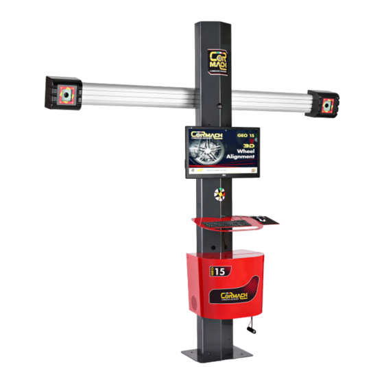
- Page 59 1 - MONITOR 2 - KEYBOARD HOLDER 3 - COLUMN 4 - PC CABINET 5 - CAMERAS 6 - BEAM Devices connection GEO 15...
- Page 60 Target Cameras GEO 15...
- Page 61 Camera cover Power switch GEO 15...
- Page 62 CAMBER KING PIN TOE-OUT ON TURN CASTER GEO 15...
- Page 63 THRUST ANGLE SET BACK GEO 15...
- Page 64 GEO 15...
- Page 65 Li/MnO2 GEO 15...
- Page 67 DECLARATION OF CONFORMITY Complies with EN ISO/IEC 17050-1 and EN ISO/IEC 17050-2 Cormach S.r.l., based in Via A. Pignedoli, 2 – 42015 Correggio (RE) – Italy, Hereby declare under own responsibility, that the following product 3D Wheel Aligner GEO 15...
- Page 69 CORMACH S.r.l. via A. Pignedoli, 2 42015 CORREGGIO (RE) ITALY Tel. +39 0522 631274 - Fax +39 0522 631284 e-mail: cormach@cormachsrl.com www.cormachsrl.com ...
Need help?
Do you have a question about the GEO 15 and is the answer not in the manual?
Questions and answers