Table of Contents
Advertisement
Quick Links
Advertisement
Table of Contents

Subscribe to Our Youtube Channel
Related Manuals for Cormach MOTO MEC


Summary of Contents for Cormach MOTO MEC
- Page 1 WHEEL BALANCERS MOTO MEC USE AND MAINTENANCE MANUAL...
- Page 3 DECLARATION OF CONFORMITY Complies with EN ISO/IEC 17050-1 and EN ISO/IEC 17050-2 Cormach S.r.l., located in Via A. Pignedoli, 2 – 42015 Correggio (RE) – Italy, Manufacturer of the wheel balancer line, model/s MOTO MEC Serial Number _____________________________ Declare under our own responsibility that the product to which this declaration relates, is in conformity...
- Page 5 RoHS DECLARATION OF CONFORMITY DECLARATION DE CONFORMITE RoHS RoHS - ÜBEREINSTIMMUNG CORMACH S.r.l. - Via A. Pignedoli, 2 - 42015 Correggio (RE) ITALY Dichiara sotto la propria esclusiva responsabilità che il prodotto: Declare on our own responsibility that the product: Déclare sous son propre responsabilité...
- Page 6 DICHIARAZIONE DI CONFORMITA’ RoHS RoHS DECLARATION OF CONFORMITY DECLARATION DE CONFORMITE RoHS RoHS - ÜBEREINSTIMMUNG EQUILIBRATRICE RUOTE AUTO EQUILIBREUSE ROUES VOITURE WHEEL BALANCER AUSWUCHTMASCHINE Alla quale questa dichiarazione si riferisce, E’ CONFORME ALLA DIRETTIVA: To which declaration refers is in CONFORMITY WITH THE FOLLOWING DIRECTIVE: Au quel cette déclaration se rapporte EST CONFORME À...
-
Page 7: Table Of Contents
CONTENTS Introduction Pag. Intended use Pag. General safety rules Pag. 3.1 Safety devices Pag. Transport and handling Pag. Unpacking Pag. Installation and commissioning Pag. 6.1 Installing the display head Pag. 6.2 Flange for motorcycle wheel Pag. 6.3 Electrical connection Pag. Installation Pag. -
Page 8: Introduction
Indicates prohibitions Indicates possible danger for the operator Cormach s.r.l. We reserve the right to make any change to products in order to improve them. Cormach s.r.l. We reserve the right to make any change to this manual without notice. -
Page 9: General Safety Rules Pag
Net weight (Kg) Gross weight (kg) Lenght (mm) Width (mm) Height (mm) MOTO MEC 80 Kg. 95 Kg. 1180 1250 If the machine is not packed, observe following precautions: PROTECT THE SHARP EDGES AT THE ENDS WITH SUITABLE MATERIAL (Bubble wrap or cardboard). -
Page 10: Unpacking
ALWAYS UNPLUG THE POWER SUPPLY CABLE FROM THE SOCKET BEFORE MOVING THE MACHINE. The environmental working conditions must comply with the following requirements: Temperature from 0° C to + 45° C Relative humidity from 20% to 95% 5. UNPACKING After removing packing, check integrity of machine making sure there are no visibly damaged parts. In case of doubt DO NOT USE THE MACHINE and consult qualified personnel (dealer or manufacturer). -
Page 11: Flange For Motorcycle Wheel Pag
Secure the head to the support with the M6 screws. Figure F6.7 Figure F6.8 Attach the head with its CPU board to the sheet metal front support (Figure F6.9). Figure F6.9 Secure the head with no. 4 M6 screws. Figure F6.10 6.2 Flange for motorcycle wheel The motorcycle flange kit is provided completed as showed in figure F6.11. - Page 12 Tighten the screws to secure the pin (Fig. F6.14 and Fig. F6.15). Figure F 6.14 Figure F6.15 Mount the motorcycle flange in the mechanical unit of the wheel balance as showed in figure F6.16. Figure F6.16 The motorcycle adaptor must be mounted in the way that the written CAL on the flange shaft and on the motorcycle adaptor are matching and aligned.
-
Page 13: Electrical Connection
Power supply cable The change of the power supply cannot be realized by the user; it must be requested to CORMACH s.r.l. or to a dealer or to an authorized service center. To accomplish the electric connection, connect the machine’s power supply cable with the plug in use in the country. -
Page 14: Installation
7. INSTALLATION 7.1 Installation area To install the machine you need a useful space on the basis of the information given in figure F7.1. 1000 Figure F7.1 From working position, the user must be able to view the machine and the surrounding area. INSTALLATION AREA MUST BE KEEP CLEAR BY POSSIBLE DANGEROUS OBJECTS. -
Page 15: Suspension Of The Use Pag
8. SUSPENSION OF THE USE In case the machine is not used for a long time it is necessary to disconnect the power supply and protect all parts that could be damaged by dust. Grease all parts that could be damaged in case of oxidation. In this specific case, protect the shaft and flange. 9. -
Page 16: Machine Dimensions
10.1 Machine dimensions Depth mm. 420 Width mm. 640 Height mm. 1250 10.2 Working range Rim size manually set inches Rim – machine distance 2 ÷ 460 Rim width 50 ÷ 500 2.0 ÷ 20.0 Rim diameter 25 ÷ 890 1.0 ÷... -
Page 17: Presentation Of The Machine
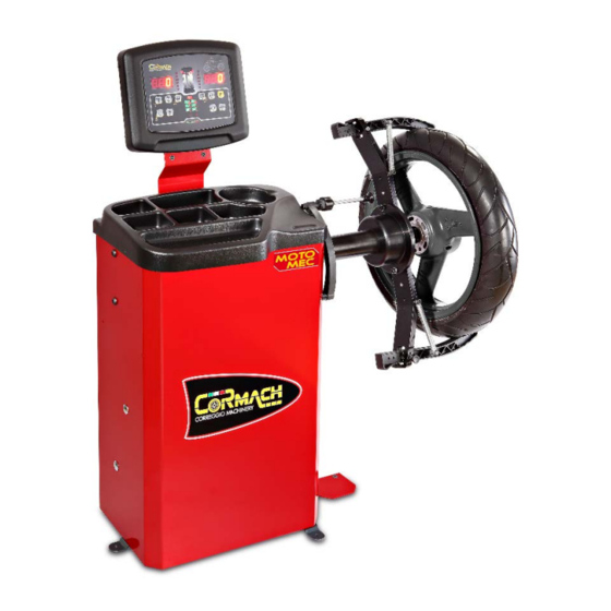
10.3 Presentation of the machine Weight tray Display/Keyboard panel Mechanical group MOTO flange Brake pedal Figure F10.1 11. SERIAL NUMBER PLATE INFORMATION 12. ORDINARY MAINTENANCE To ensure the efficiency of machine and its proper functioning is essential to follow the manufacturer’s instructions by performing periodic cleaning and routine maintenance. -
Page 18: Control Panel
13. CONTROL PANEL The machine control panel is shown in Figure F13.1. The control panel allows the operator to give commands and enter or edit data. The same control panel displays the balancing results and machine messages. The functions of the various parts of the control panel are described in table T13.1. -
Page 19: Keyboard
13.1 Keyboard For your convenience, the keys in this manual are numbered from [P1] to [P10] as shown in Figure F13.1. Next to the reference numbers of the keys, there are icons of the keys themselves for easy reading. The ten buttons have a main function indicated by a symbol in the levelled square, and a secondary function indicated by a small icon located nearby. -
Page 20: Normal, Service, Stand By Operating Modes Pag
13.2 STANDARD, SERVICE, STAND-BY operating modes The machine features three operating modes: • STANDARD mode. This mode is enabled after the machine is turned on and it is possible to perform the wheels balancing; • SERVICE mode. In this mode various utility programs are available for setting parameters (such as grams or ounces) or checking the machine operations (such calibration);... -
Page 21: Machine Calibration For The Moto/Quad Wheel Type Pag
14.2 Machine calibration for the MOTO/QUAD wheel type To perform machine calibration, you must first provide for the following material: • A balanced wheel with an aluminum or a steel rim (Recommended dimensions: Minimum Diameter 17”). • Calibration weight supply as standard. To perform the machine calibration, proceed as follows: Phase Description... - Page 22 Rotate manually the motorcycle flange so that the wheel will turn counterclockwise. After the launch put the MOTO flange in the vertical position and the display shows the message on the side, apply the calibration weight on the inside as shown in figure F14.2. The Figure F14.2 calibration weight is applied on the hole that has stamped the "CAL"...
-
Page 23: Use Of The Machine In Normal Mode Pag
Rotate manually the motorcycle flange so that the wheel will turn counterclockwise. At the end of the spin, the MOTO wheel type calibration is finished and the machine will switch to NORMAL mode, ready to run the balancing. How to exit the MOTO wheel type calibration of the machine At any time it is always possible to exit the calibration procedure during its progress by pressing [F+P3] . -
Page 24: Program Type Pag
Static Plane Internal plane External plane Static Plane acquisition system MOTO MEC In table T15.2 the symbol “H12” indicates that the angular position of the weight is at 12 o’clock. Use and maintenance manual – 10/2016 Rev. 3 Page 18... -
Page 25: Wheel Type Pag
15.2 Wheel Type The machine allows choosing one of three different Wheel Types, as listed in table T15.3. Table T15.3: Wheel types available Wheel type Vehicle Notes MOTO Motorcycles Default at switching on QUAD Quad Each of the above programs sets specific values to measure wheel sizes and calculate imbalances. The special features of each program are listed in the following paragraphs. -
Page 26: Entering Wheel Dimensions
The balancing of wheel type QUAD could be performed also with ALU Program Type by pressing the button [P8] ; STATIC Program Type by pressing the button [P10] 15.3 Entering wheel dimensions The dimensions of the wheel to balance can be entered in manual mode only. Note: all the machines are equipped with a graduated scale for manually measuring the distance. -
Page 27: Hidden Weights Program
16. HIDDEN WEIGHTS PROGRAM This program divides the external weight W in two weights W1 and W2 (smaller than the initial external weight W) located in any two positions selected by the operator. The two weights W1 and W2 must form a maximum angle of 120° including the external weight W, as shown in Figure F16.1. Figure F16.1: Hidden Weights Program: valid and invalid conditions for use. -
Page 28: Utility Programs
If the angle chosen is higher than 120°, the machine displays error code Err 051 thus indicating to choose another point. If instead the angle is less than 120°, the machine will display the message shown in Figure F17.3, allowing the operator to continue with the next step;... -
Page 29: Selection Of The Static Imbalance Display Pag
To return to viewing in X5 resolution (low resolution), press [F+P1] . The machine will display the message visible in Figure F17.2 for one second and the LED next to the button will turn off. Imbalance values are now displayed in X5 resolution (low resolution). - Page 30 [P4] - Grams/ounces selection This button allows you to display and/or change the currently selected weight unit of measurement. The units available are grams (GRAM) e ounces (OUNCE). DISPLAY OF CURRENT UNIT To display the current unit of measurement, briefly press [P4] .
- Page 31 [F+P4] - Read launch number counter By pressing this button, the total number of balancing launches run by the machine is displayed. The number of launches is shown on both displays. Figure F18.3 shows an example of a machine display that has run 1234 balancing launches. Figure F18.3: Display of the number of balancing launches [F+P5] - Parameters...
- Page 32 SIG Pick-up signals test This program allows you to check the pick-up signal. To run the test, you will need to mount a balanced wheel with a steel rim, 15” in diameter and 6” in width (or as similar as possible) on the machine. A 50 gram weight must be applied on the external side of the wheel.
-
Page 33: Signals Pag
19. SIGNALS When abnormal operating conditions occur, the machine emits two types of signal: • Error • Warning The Error signal is always accompanied by a triple beep indicating that the machine cannot run the command given by the operator, or, during operation, conditions were encountered that prevent the action in progress from continuing. -
Page 34: Warning Codes Pag
19.2 Warning codes The machine alerts the operator of the warning codes by alternating the display of the warning code with the brief description (in English) of the warning and remains in this status until the operator has pressed any key (except for [P7] Table T19.2: Warning codes Warning code Brief... - Page 36 CORMACH S.r.l. via A. Pignedoli, 2 42015 CORREGGIO (RE) ITALY Tel. +39 0522 631274 - Fax +39 0522 631284 e-mail: cormach@cormachsrl.com www.cormachsrl.com...
Need help?
Do you have a question about the MOTO MEC and is the answer not in the manual?
Questions and answers