Table of Contents
Advertisement
Advertisement
Table of Contents

Subscribe to Our Youtube Channel
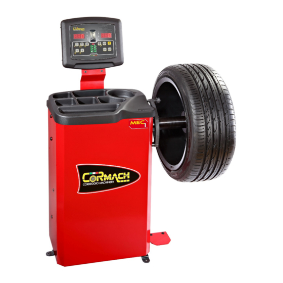
Summary of Contents for Cormach MEC 1
- Page 1 EQUILIBRATRICI MEC 1 – MEC 1 BAT TECHNICAL SUPPORT MANUAL...
-
Page 3: Table Of Contents
9. TROUBLESHOOTING..................................12 10. DESCRIPTION OF MACHINE.................................13 Cormach s.r.l. reserves the right to make any change to products in order to improve them. Cormach s.r.l. reserves the right to make any change to this manual without notice. Technical Support Manual – 05/2015 Rel. 0... -
Page 4: Service Mode
1. SERVICE MODE The machine can run in two different modes: • NORMAL Mode: this mode is pre-set upon activation of the machine and allows the wheels to be balanced. • SERVICE Mode: principally, this mode refers firstly to the SERVICE technical personnel and secondly to the end user. In SERVICE mode, several options are available to configure, calibrate, and test the machine. -
Page 5: Enc Encoder Disc Test
To access the "TEST Programs" Menu, proceed as follows (See Figure F2.1): Enter the SERVICE mode by pressing [F+P3] and will be displayed the following messages Press keys [F+P9] to access the “TEST Programs” Menu; Browse the list of the Menus with keys [P4] or [P5] until the option required is displayed. -
Page 6: Rpm Shaft Rotation Speed Test
RPM Shaft rotation speed test This menu option allows you to run the shaft rotation speed test. When you access this option, the display shows the message RPM 000 as shown in figures F2.4 and F2.5. Figure F2.4: Shaft rotation speed test message Figure F2.5: Shaft rotation value message To perform a realistic measurement, we recommend mounting a medium size wheel on the shaft. -
Page 7: Dpy Display Test
If both pick-up signals differ from, but are similar to the values indicated in table T9.2 check if: • The dimensions of the wheel are different from those of the reference wheel; • The wheel is not balanced; • The 50 grams of the imbalance weight are placed on the inner side; •... -
Page 8: Tas Keyboard Test
Tas Keyboard Test This menu option allows you to run the keyboard test. When you access this option, the RH display shows the message P . (See figures F2.10 and F2.11). Figure F2.10: Keyboard Test Message Figure F2.11: Keyboard value message Press one key at a time to make sure that the control corresponds to the key. -
Page 9: Ret Return
RET Return This option allows you to return to the SERVICE mode, as shown in figures F2.14 and F2.15. Figure F2.14: Return message Figure F2.15: SERVICE mode message 3. MENU PARAMETERS ACCESS (with password) The Parameters MENU allows you to run various operations reserved to technical personnel, such as re-setting the revolution counter - SPIN. -
Page 10: Spn Revolution Counter Reset (Spin)
SPn Revolution counter reset (spin) This menu option allows you to reset the machine revolution counter. Figure F3.5: Revolution counter reset message Confirm to reset the revolution counter (the LH display will show yEs). Press [F+P5] to confirm or any other key to cancel the operation. -
Page 11: Machine Calibration
Condition Status Who must perform it When the machine is manufactured Mandatory Cormach srl When the machine is installed at the site of the end customer Mandatory SERVICE technical personnel When the CPU-C1 electronic control unit is updated or replaced... -
Page 12: How To Exit The Car/Suv Wheel Type Calibration
10. Manually rotate the wheel until a value of 50 appears on the right display. Apply the 50 g weight at the 12 o'clock position on the external side of the wheel; 11. Manually run a launch by acting on the locking ring with knobs; 12. -
Page 13: Acoustic Signals
OPERATOR WARNING: Launch with weight on the Remove the weight from the internal side and INN IMB CONFIRMATION internal side during the Cal3 calibration repeat the launch. If the error persists, contact phase. In this phase, the weight must be technical support. -
Page 14: Special Visual Signals
8. SPECIAL VISUAL SIGNALS The machine gives special visual signals in certain cases. The special visual signals are listed in table T8.1. Table T8.1: Special visual signals Signal Meaning Notes Three dots lit on one or Imbalance exceeds 999 grams. This signal can be triggered due to: both displays •... -
Page 15: Description Of Machine
10. DESCRIPTION OF MACHINE The figures F10.1 e F10.2 show a detailed scheme of the machine. Figure F10.1: Electrical wiring of the machine without internal battery (MEC 1) It is possible to order the following codes: 1 – Cod. 21201019: Power supply board 2 –... - Page 16 Figure F10.2: Electrical wiring of the machine with internal battery (MEC 1 BAT) It is possible to order the following codes: 1 – Cod. 21201019: Power supply board 2 – Cod. 21201028: CPU-C1C board Technical Support Manual – 05/2015 Rel. 0...
- Page 17 Unità centrale di processo CPU-C1C This is the most complex machine system. The board is positioned behind the control panel. The CPU-C1 board collects the analogue signals of pick-ups A and B and the sensor data (encoder disc), activates the electric motor, processes the pick-up signals and the sensor data, and displays the balancing results.
- Page 19 CORMACH S.r.l. via A. Pignedoli, 2 42015 CORREGGIO (RE) ITALY Tel. +39 0522 631274 - Fax +39 0522 631284 e-mail: cormach@cormachsrl.com www.cormachsrl.com...


Need help?
Do you have a question about the MEC 1 and is the answer not in the manual?
Questions and answers