Table of Contents
Advertisement
Quick Links
Advertisement
Table of Contents

Related Manuals for Cormach MEC 200 TRUCK


Summary of Contents for Cormach MEC 200 TRUCK
- Page 1 WHEEL BALANCERS MEC 200 TRUCK MEC 200-C TRUCK USE AND MAINTENANCE MANUAL...
- Page 3 DECLARATION OF CONFORMITY Complies with EN ISO/IEC 17050-1 and EN ISO/IEC 17050-2 Cormach S.r.l., located in Via A. Pignedoli, 2 – 42015 Correggio (RE) – Italy, Manufacturer of the wheel balancer line, model/s MEC 200 TRUCK Serial Number _____________________________ Declare under our own responsibility that the product to which this declaration relates, is in conformity...
- Page 5 RoHS DECLARATION OF CONFORMITY DECLARATION DE CONFORMITE RoHS RoHS - ÜBEREINSTIMMUNG CORMACH S.r.l. - Via A. Pignedoli, 2 - 42015 Correggio (RE) ITALY Dichiara sotto la propria esclusiva responsabilità che il prodotto: Declare on our own responsibility that the product: Déclare sous son propre responsabilité...
- Page 6 DICHIARAZIONE DI CONFORMITA’ RoHS RoHS DECLARATION OF CONFORMITY DECLARATION DE CONFORMITE RoHS RoHS - ÜBEREINSTIMMUNG EQUILIBRATRICE RUOTE AUTO EQUILIBREUSE ROUES VOITURE WHEEL BALANCER AUSWUCHTMASCHINE al quale questa dichiarazione si riferisce, E’ CONFORME ALLA DIRETTIVA: to which declaration refers is in CONFORMITY WITH THE FOLLOWING DIRECTIVE: au quel cette déclaration se rapporte EST CONFORME À...
-
Page 7: Table Of Contents
Fire prevention means to use Page Cormach s.r.l. We reserve the right to make any change to products in order to improve them. Cormach s.r.l. We reserve the right to make any change to this manual without notice. Use and Maintenance Manual – 09/2016 Rel. 0... -
Page 8: Introduction
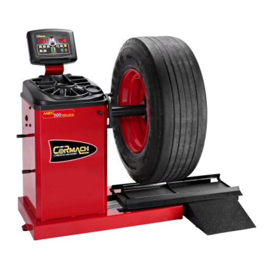
1000 1060 1500 Figure F1.2 MEC 200 TRUCK with Wheel Guard (optional) 1. INTRODUCTION This manual is an integral part of the machine and it must to stay with wheel balancer until the scrapping of the machine. Read carefully each section of this manual before using the machine. The manufacturer is not responsible for damages and injury caused by failure to follow the instructions of this manual. -
Page 9: Intended Use
Net weight (Kg) Gross weight (kg) Lenght with lift (mm) Width (mm) Height (mm) MEC 200 TRUCK 1500 1340 If the machine is not packed, observe following precautions: PROTECT THE SHARP EDGES AT THE ENDS WITH SUITABLE MATERIAL (Bubble wrap or cardboard). -
Page 10: Unpacking
SLING WITH STRAPS OF AT LEAST 200 cm IN LENGHT AND WITH A HIGHER FLOW RATE OF 3000 kg. DO NOT FORCE ON SHAFT AND/OR FLANGE (See pictures F4.1 and F4.2). Figure F4.1 Figure F4.2 ALWAYS UNPLUG THE POWER SUPPLY CABLE FROM THE SOCKET BEFORE MOVING THE MACHINE. The environmental conditions of work must be conform to the following requirements: Temperature from 0°... - Page 11 Fit the sheet metal rear support by running the cables as shown in Figure F6.2 and screw no. 4 M6 screws (Figure F6.3). Figure F6.2 Figure F6.3 Prepare the sheet metal front support by running the cables as shown in figure F6.4. Figure F6.4 Fit the sheet metal front support.
-
Page 12: Installing Lift
Attach the head with its CPU board to the sheet metal front support (Figure F6.9). Figure F6.9 Secure the head with no. 4 M6 screws. Figure F6.10 6.2 Installing lift Fit the filter+regulator in the wheel balancer rear frame and link it to the relevant pipe. - Page 13 Fit the lever for the lift control (fig.6.13). Slide the lift and make it lift by the relevant control. Figure F6.13 Figure F6.14 Fix the ramp support to the lift with the relevant screws. Figure F6.15 Fix the lift to the wheel balancer base with the relevant screws.
-
Page 14: Installing Wheel Guard And Wheel Guard Support (If Present)
Set the spacers to assure the correct lying on the ground of the ground. Figure F6.17 Figure F6.18 Fix the ramps for the wheel spinning up and down. Figure F6.19 6.3 Installing wheel guard and wheel guard support (if present) The wheel protection cover (and its support) is an ACCESSORY. -
Page 15: Electrical Connection
The standard version of the machine must be connected to a mains 230V SINGLE PHASE. The change of the power supply cannot be realized by the user; it must be requested to CORMACH s.r.l. or to a dealer or to an authorized service center. -
Page 16: Installation
IN CASE OF OPERATIONS ON ELECTRIC PARTS, CABLES ENGINES OR ANY ELECTRIC DEVICES, IT IS NECESSARY TO CUT OFF THE ELECTRICITY. DO NOT REMOVE, DAMAGE AND MAKE COMPLETELY ILLEGIBLE THE STICKERS OF DANGER, WARNING, INSTRUCTIONS AND CAUTION. REPLACE ANY MISSING, DAMAGED OR ILLEGIBLE STICKERS. THE STICKERS CAN BE FOUND AT THE NEAREST DEALER OF MANUFACTURER. -
Page 17: Environmental Information
9. ENVIRONMENTAL INFORMATION THE DISPOSAL PROCEDURE DESCRIBED BELOW ONLY APPLIES TO MACHINES WITH THE SYMBOL OF THE WASTE BIN WITH A BAR ACROSS IT ON THEIR DATA PLATES. The crossed-out bin symbol, placed on the product and on this page, reminds the user that the product must be disposed of properly at the end of its life. -
Page 18: Working Range
Machine weight (without accessories) 270 Kg. Noise Level < 70 dB(A) Table T10.1: Functions for machine models Functions MEC 200 TRUCK NOTES Data wheel manual acquisition • Balancing accuracy with CAR wheel ± 1 g. Balancing accuracy with TRUCK wheel ±... -
Page 19: Presentation Of The Machine
10.3 Presentation of the machine Distance/Diameter sensor Display/Keyboard panel Weightray Mechanical group Pines for cones Pneumatic lift Figure F10.1 11. SERIAL NUMBER PLATE INFORMATION 12. MAINTENANCE To ensure the efficiency of machine and its proper functioning is essential to follow the manufacturer’s instructions by performing periodic cleaning and routine maintenance. -
Page 20: Control Panel
13. CONTROL PANEL The machine control panel is shown in picture F13.1. The control panel allows the operator to give commands and enter or modify data. The same control panel displays the balancing results and machine messages. The functions of the various sections of the control panel are described in table T13.1. -
Page 21: Keyboard
13.1 Keyboard In this manual, the keys are numbered for convenience from [P1] to [P10] as shown in picture F13.1. Beside the key reference numbers the key symbols (for an easy-to-read) are shown. The ten buttons have a main function indicated by a symbol in the big circle and a secondary function indicated by the symbol in the small circle located along side. -
Page 22: Operating Modes Standard, Service, Stand-By
Note: the keys [P7] , [P8] Start and [P10] Stop are not used to access settings, programs or Menus. 13.2 Operating modes STANDARD, SERVICE, STAND-BY The machine features three operating modes: • STANDARD mode. This mode is enabled after the machine is turned on and it is possible to perform the wheels balancing; •... -
Page 23: Machine Calibration For The Truck Wheel Type
14.2 Machine calibration for the TRUCK wheel type The calibration for the TRUCK wheel type is unique. To perform machine calibration, you must first provide for the following material: • A balanced wheel with steel rim that has the following dimensions: Diameter 22.5”. It is not possible to use wheels with aluminum rims;... -
Page 24: Machine Calibration For The Car/Suv Wheel Type
Press [P8] key Start . The machine will run a launch. At the end of the spinning, the inverter brake stops the wheels in the position where showing the value of 300 on the left display. Remove the 300 gr weight fixed on the internal side and fix it on the external side of the wheel, at 12H. - Page 25 Mount the wheel on the shaft and enter the wheel dimensions by pressing the [P1] , [P2] , [P3] to select the dimensions to change, and the [P4] [P5] to edit the value. If the dimensions of the wheel have been entered before accessing the calibration program, this step can be skipped.
-
Page 26: Use Of The Machine In Normal Mode
15. USE OF THE MACHINE IN NORMAL MODE Display/keyboard panel on the machine To use the machine, you must select or set as follows: • Program Type (program for wheels with steel or special aluminum rim). Default = program for wheels with steel rims; •... -
Page 27: Wheel Type Selection
The position of the balancing weights along the section of the rim in the various Program Types is shown in picture F15.1. Figure F15.1: Position of the weights in the various Program Types along the section of the rim Angular position of the balancing weights in the several Program Type is shown in table T15.2. Table T15.2: Angular position of the balancing weights in the various Program Types Program Type Machine... -
Page 28: Truck Wheel Type
15.2.2 TRUCK wheel type The selection of TRUCK wheel type allows the balancing for the TRUCK wheels. To select the TRUCK wheel type press the key [P6] repeatedly until the Wheel Type light indicator for TRUCK is lighted on. See table T15.3. 15.2.3 SUV wheel type (Off-Roads vehicles) The selection of SUV wheel type allows the balancing of wheels for off-road vehicles. -
Page 29: Entering Wheel Size For Program Types Als1, Als2
Press the [P3] key to change the diameter and press the [P4] or [P5] within 1.5 seconds to enter the read value. If neither of these two buttons is pressed in this time limit, the machine will return to the previous display. - Page 30 buttons is pressed in this time limit, the machine will return to the previous display. In this case, you can press the [P3] key again [P3] to enter or edit the data; 10. Press [P3] twice in quick succession to view da2 (external plane diameter) and within about 1.5 seconds press [P4] or [P5] to enter the value obtained with one of the two methods specified in the below note.
-
Page 31: Use Of The Program Types Als1 Or Als2
Figure F15.5: Acquisition of the external plane distance in ALS1 and ALS2 Program Types 15.3.3 Use of the Program Types ALS1 or ALS2 manually enter the values of the two dimension pairs di1/da1 and di2/da2 proceed as indicated in section 15.3.2 Entering wheel size for Program Types ALS1, ALS2. - Page 32 Hidden weights program with sensors disabled To use the HIDDEN WEIGHTS program, proceed as follows: Perform wheel balancing without applying the external weight; Rotate the wheel manually until all external imbalance search LEDs light up (see detail [9] in Figure F16.1); For ease of use, make a reference mark on the tyre in the imbalance position at 6 o'clock;...
-
Page 33: Second Operator
17. SECOND OPERATOR The machine has two separate memories allowing two operators to work simultaneously with different settings. This feature can make operations at the workshop quicker because when, for example, an operator is busy with removing or remounting a tyre, the other operator can use the machine to perform balancing operations and vice versa. In this manual, the two operators are defined as operator 1 and operator 2. -
Page 34: Utility Programs
18. UTILITY PROGRAMS Utility programs are available only in NORMAL mode. 18.1 Selecting the imbalance display resolution The machine has two wheel imbalance display resolutions. The two resolutions are defined as X1 (high resolution) and X5 (low resolution). The resolution with which the imbalances of the wheel are displayed varies depending on the weight unit of measurement as indicated in table T18.1. -
Page 35: Inverter Brake
18.3 Inverter brake The inverter brake is useful to stop the wheel in the first angle unbalance position and search the second angle unbalance position, making easier some other operations just like the sticking or removal of the counterweight. To activate the inverter brake press the key [P9] 18.4 SWI wheel stop procedure on the positions of imbalance Machines equipped with the inverter brake are capable of automatically stopping the wheel at the first imbalance angular position that is reached during rotation. -
Page 36: Service Mode
19. SERVICE MODE In this mode, the machine allows the user to enter certain settings (for example, selection of the units of measurement) or use special testing programs (to verify machine functioning) or configuration. Some test and configuration programs are included in this Menu while the setting programs are available with direct access by means of the buttons. - Page 37 [P5] Select inches/millimeters This button allows you to display and/or change the wheel’s unit of dimension currently selected. The units available are inches (INCHES) and millimeters (MILLIM). DISPLAY OF CURRENT UNIT To display the current unit of measurement briefly press [P5] .
- Page 38 [F+P9] MENU Test Programs This menu allows you to run tests for some machine functions. The Menu has the following options: • Enc Encoder disk test; • RPM Number of shaft RPMs test; • SIG Pick-up signals test; • dPy Display test; •...
-
Page 39: Signals
tAS Keypad test The keypad test program is used to check the operation of all the keys on the control panel. Every time a button is pressed the code of that key will appear on the display: for example, by pressing [P8] key Start the code “P8”... -
Page 40: Error Codes
20.1 Error Codes The machine indicates error conditions by alternating the display of the error code with a brief description (in English) pf the cause of the error. The list of error codes and brief descriptions are reported in table T20.1. The machine displays the code for different times depending on the code of said error, as indicated in the “Error displayed”... -
Page 41: Acoustic Signals
The error code can be exited in the following ways: OPERATOR CONFIRMATION The machine exits the error code display when the operator presses any key (except for [P7] The machine exits the display of the error code when the operator takes an action related to the error OPERATOR ACTION code itself. -
Page 42: Fire Prevention Means To Use
21. FIRE PREVENTION MEANS TO USE Dry materials Flammable liquids Electrical equipment Hydraulic Foam Powder YES* YES* YES*: Can be used in the absence of more appropriate means or for small fires. The information in the table above is general and can be used as a rough guide. The responsibility for the use of each type of extinguisher must be obtained from the manufacturer. - Page 44 CORMACH S.r.l. via A. Pignedoli, 2 42015 CORREGGIO (RE) ITALY Tel. +39 0522 631274 - Fax +39 0522 631284 e-mail: cormach@cormachsrl.com www.cormachsrl.com...
Need help?
Do you have a question about the MEC 200 TRUCK and is the answer not in the manual?
Questions and answers