Table of Contents
Advertisement
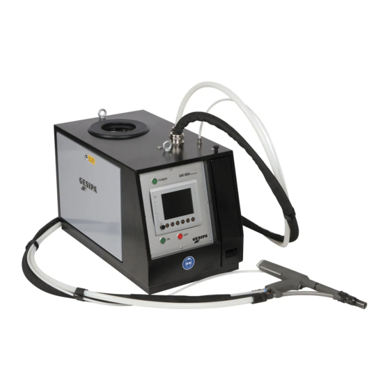
Automatic Blind Riveting Unit
GESIPA Blindniettechnik GmbH
Nordendstraße 13-39
64546 Mörfelden-Walldorf
Germany
GAV electronic
Model 8000
Model 8000 eco
Fully Automatic Blind Riveting System
Year of construction . . . . . . . .
Device No. . . . . . . . . . . . . . . . . .
Operating Instructions
With Spare Parts List and Accessories
T +49 (0) 6105 962 0
F +49 (0) 6105 962 287
info@gesipa.com
www.gesipa.com
Advertisement
Table of Contents

Related Manuals for Gesipa 8000


Summary of Contents for Gesipa 8000
- Page 1 Automatic Blind Riveting Unit GAV electronic Model 8000 Model 8000 eco Fully Automatic Blind Riveting System Year of construction ..Device No....
-
Page 2: Table Of Contents
- 1 - Table of Contents Table of Contents Section Page Dimension Sheet, Technical Data and Working Range ....Intended Use and Safety Information ..........5 - 6 Environmental Information, Recycling, Declaration of Conformity.. Transportation and Installation ............Start-Up and Operation ................ 9 - 10 Functional Principle ................ - Page 3 28.5 Profile List Selection ..............28.6 Profile Selection, Direct ............. 28.7 Profile Selection, In Steps ............28.8 Process Evaluation ..............28.9 Component Evaluation .............. 28.10 Other Functions ..............Teach-in of Measurement Range.the Displacement Sensor 118 - 119 (WS1) Not included in GAV-8000 eco...
- Page 4 - 3 - Table of Contents Table of Contents Spare Parts List Overview of Assemblies Spare Parts List Page Group 1: Pneumatics Assembly ............2 – 3 Group 2: Blind Riveting Gun ..............4 – 10 Group 3: Hydraulic Booster Unit ............11 – 12 Group 4: Separator ................
-
Page 5: Dimension Sheet, Technical Data And Working Range
- 4 - Dimension Sheet, Technical Data and Working Range Supply unit Weight: 100 kg Volume of spent mandrel container: approx. 1800 - 5500 pieces (3.5 l) depending on size Electrical system - Nominal voltage: 230 Volt ~ 50 Hz - Nominal current: <... - Page 6 - 4-R - Dimension Sheet, Technical Data and Working Range Supply unit Weight: 100 kg Volume of spent mandrel container: approx. 1800 - 5500 pieces (3.5 l) depending on size Electrical system - Nominal voltage: 230 Volt ~ 50 Hz - Nominal current: <...
- Page 7 - 4-U - Dimension Sheet, Technical Data and Working Range Supply unit Weight: 100 kg Volume of spent mandrel container: approx. 1800 - 5500 pieces (3.5 l) depending on size Electrical system - Nominal voltage: 230 Volt ~ 50 Hz - Nominal current: <...
- Page 8 - 4-UA - 1-UA Dimension Sheet, Technical Data and Working Range Supply unit Weight: 100 kg Volume of spent mandrel container: approx. 1800 - 5500 pieces (3.5 l) depending on size Electrical system - Nominal voltage: 230 Volt ~ 50 Hz - Nominal current: <...
-
Page 9: Intended Use And Safety Information
- 5 - Intended Use and Safety Information Intended use The blind riveting system is intended solely for the purpose of processing blind rivets that are suitable for automatic machines. Any other than the intended use shall be deemed as not for the intended purpose. - Page 10 Safety Information Accident prevention Only persons may work with the GAV-8000 who have read and understood the operating instructions and safety information - instruction have checked the device and workplace for potential danger to life and limb before starting...
-
Page 11: Environmental Information, Recycling, Declaration Of Conformity
- 7 - Environmental Information, Recycling, Declaration of Conformity Environmental information Noise emission of the blind riveting system. Applicable directives: 2006/42/EC: 78/84 dB Continuous sound level: without/with feed unit Measurement uncertainty K= 3 dB Vibration of GAV gun. Applicable directives: 2006/42/EC: <2.55 m/s Measurement uncertainty K=1 m/s²... -
Page 12: Transportation And Installation
- 8 - 4 Transportation and Installation Transportation Corresponding to the agreement, the blind riveting system is delivered and installed or dis- patched upright in a special wooden container. Left unpacked, the blind riveting system can be moved with a trolley, available as an acces- sory, on an even floor. -
Page 13: Start-Up And Operation
- 9 - Start-Up and Operation Maintenance unit Note! Prior to start-up, read and follow the GAV operat- ing instructions and safety information. Also ob- serve the generally applicable Occupational Health and Safety Regulations. Start-up Connect the device to the compressed air sup- ply system. - Page 14 - 10 - Start-Up and Operation jaws corresponding to the diameter of the blind rivet mandrel are used. The jaw sizes Jaws are graduated as follows: Blind rivet mandrel diameter 1.5 to 2.1 mm 2.1 to 2.7 mm 2.7 to 3.3 mm 3.3 to 3.65 mm Vibration feed unit the adjustable baffle ahead of the outlet...
-
Page 15: Functional Principle
- 11 - Functional Principle The fully automatic GAV electronic blind riveting system consists of a supply unit and a practical blind riveting gun, both connected by a flexible hose assembly. The supply unit contains an electronic controller with dialogue unit, two hydraulic pressure boosters, an electrical blind rivet feed unit and a spent mandrel evacuation system with spent mandrel container. -
Page 16: Functional Description
- 12 - Functional Description 7 Functional Components of the Blind Riveting Gun The schematic diagrams and descriptions below illustrate the control and functional procedures in simplified form. Spreader nosepiece - 3-piece - (1) Loads the blind rivet positioned in the gun head into the processing position. Closing sleeve (2) Locks and unlocks the spreader nosepiece (1). - Page 17 - 13 - Functional Description 7 Functional Assemblies of the Supply Unit Blind rivet separator (II) Component part of the blind rivet feed system. Here the blind rivets (10) are separated and fed by compressed air via the feed hose to the blind riveting gun. Hydropneumatic pressure booster (III) Applies pressure to the pressure piston (8), thus initiating the release stroke of the spreader nosepiece.
- Page 18 - 14 - Functional Description 7 Functional Components of the Blind Riveting Gun Functional diagram 1 The reset air initiated by valve (V) is applied and holds the complete piston unit (7/8) in the end position. The closing sleeve (2) locks the segments of the spreader nosepiece (1) at their re- cess.
- Page 19 - 15 - Functional Description 7 Functional Diagrams and Description Functional diagram 3 The pressure booster (IV) continues applying pressure to the pull piston (7) so that it moves to the rear end position. Valve (V) switches to vent off the reset air. The stop piston (5) and jaw tube (4) are relieved and the jaws (3) release the blind rivet mandrel (9).
- Page 20 - 16 - Functional Description 7 Functional Diagrams and Description Functional diagram 5 The valve (V) releases the reset air and the pull piston (7) as well as the piston in the pressure booster (IV) are reset to their initial position. At the same time, the pressure booster (III) applies pressure to the pressure piston (8) to execute the release stroke for the spreader nosepiece (1).
-
Page 21: Operation
- 17 - Operation 8.0 Overview 8000 Operating Controls Graphic Display Menu Structure Main Menu Error Messages Access Authorisation Manual Operation Parameter Settings Data Selection 8.10 Text Entry... - Page 22 - 18 - Operation 8.1 Operating Controls Power switch Rotary knob button Function keys button button F1-F6 1. POWER switch (master switch) connects the power supply (230 V/50 Hz or 110 V/60 Hz). lights green. ON button activates various control functions (depending on the display menu). sets GAV to home position.
- Page 23 - 19 - Operation 8.2 Graphic Display Title bar Dialogue unit Graphic display Display Function bar The graphic display is part of the dialogue unit and enables interactive operation of the GAV de- vice. The graphic display shows statuses and parameters, displays messages and visualises in- ternal procedures.
- Page 24 Process Data 20 Days Process Data Process Data Day Process Counter Process Counter Operating Data Acquisition Operating Data Acquisition Access Codes Access Codes Time and Language Time and Language System Information System Information GRivCheck PC Mode GESIPA GESIPA Not included in GAV-8000 eco...
- Page 25 - 21 - Operation 8.4 Main Menu After being switched on and in normal operation mode, the GAV device is set to to the main menu AUTO. AUTO main menu Status "Ready" Start option "Hand" (hand trigger) Navigation: AUTO Title bar Status AUTO-OFF (press ON)
- Page 26 - 22 - Operation 8.4 Main Menu If the start conditions are met in AUTO mode, a cycle can be triggered with one of the active start options (shown in the title bar). The current device status is then shown in the title bar of the main menu.
- Page 27 - 23 - Operation 8.5 Error Messages Device faults and malfunctions are shown abbreviated in white text in red fields in the AUTO main menu, warnings flash. Information on the cause of fault can be found in the corresponding menus in the "GAV Settings" area. AUTO main menu Status "Home position"...
- Page 28 - 24 - Operation 8.5 Error Messages Submenu Error message Remedy Navigation Nosepiece WS3 Small Pressure Booster Settings Spreader nosepiece of GAV gun - Press OFF button. ►MAN ►Menu was not closed. - Remove blind rivet. ►GAV settings - Press ON button. ►Small pressure booster Separator Separator Settings...
- Page 29 - 25 - Operation 8.5 Error Messages Direct menu selection: To simplify the search for the required menu with information of the cause of fault and to there- fore shorten the navigation path, the selection can be switched to the displayed error messages with in the main menu.
- Page 30 An additional window appears in the menu to enter the access code, the navigation bar chang- es accordingly. The title bar of the window shows which access code is to be entered, the Ser- vice code or the GESIPA code. The access code is entered using the digits 4 .
- Page 31 - 27 - Operation 8.7 Manual Operation GAV functions can be executed manually in the MAN menu. Device faults are displayed in the same way as in the AUTO main menu, however, they are not start conditions. For safety rea- sons, the active start options in the AUTO main memory are blocked in the entire manual area.
- Page 32 - 28 - Operation 8.8 Parameter Settings Set parameters are represented and set in the same way in all menus. Setting ranges and step width can be limited depending on the parameter and type of data. Parameters requiring a high degree of accuracy are set in multiple stages. Whole numbers and decimal places can be set in two steps, large values initially in steps of hundred and then of one.
- Page 33 Settings" menu. The profile to be loaded can be selected in the displayed window. The number of the selected profile and its change index are shown in the status bar. The example is from the setting process monitoring area and does not apply to the GAV-8000 eco...
- Page 34 - 30 - Operation 8.10 Text Entry It is necessary to enter text in various menus. An additional window appears for Text entries, the navigation bar changes accordingly. The title bar of the window shows the expected text entry. The entered text with the number of text characters still available is shown in the entry line in the window.
-
Page 35: Gav Settings
- 31 - GAV Settings 9.0 Overview Vibration Feed Unit Pressure Sensors Large Pressure Booster Small Pressure Booster Separator Blow Air Mandrel Evacuation Cycle Additional Functions 9.10 PLC Activation 9.11 Continuous Test 9.12 I/O Test 9.13 PLC Interface Test... -
Page 36: Vibration Feed Unit
- 32 - GAV Settings 9.1 Vibration Feed Unit Vibration Feed Unit Settings Menu Proximity switch NS1 Navigation: AUTO ►MAN ► Menu ► GAV settings ► Vibration feed unit Vibration Feed Unit Settings (The setting of the proximity switch NS1 is described in Section 9.5 "GAV Settings" - "Separa- tor".) Feed rate Controls the feed rate of the vibration feed unit. -
Page 37: Pressure Sensors
- 33 - GAV Settings 9.2 Pressure Sensors DS1/DS2 Pressure sensor settings menu Navigation: AUTO ►MAN ► Menu ► GAV settings ► Pressure sensors DS1 System pressure Monitors the compressed air supply to GAV (for settings see Section 5 "Start-Up and Operation"). Max. - Page 38 Navigation: AUTO ►MAN ► Menu ► GAV settings ► Pressure sensors ► Cal GESIPA code Calibration DS1 Signal type Signal type of pressure sensor. Measuring range Measuring range of pressure sensor. Calibration DS2 Signal type Signal type of pressure sensor.
- Page 39 - 35 - GAV Settings 9.2 Pressure Sensors Not in GAV-8000 DS3 Pressure Sensor Calibration and Basic Setting The DS3 pressure sensor is adapted at the connection for the hydraulic line of the large pressure booster. The calibration data "Signal Type" and "Measuring Range" are set in the "DS3 Pressure Sensor Calibration"...
-
Page 40: Large Pressure Booster
►MAN ► Menu ► GAV settings ► Large pressure booster GESIPA code WS1 Cycle switching points The switching points control the sequences within the processing cycle. The setting range is the entire measuring range as from sensor zero point. Riveting gun air Switches off the riveting gun air at the end of the power stroke, the jaws are opened and the spend mandrel released. - Page 41 Navigation: AUTO ►MAN ► Menu ► GAV settings ► Large pressure booster ► Cal GESIPA code Calibration WS1 Signal type of displacement sensor. Signal type Measuring range of displacement sensor. Measuring range Zero point Zero point of displacement sensor.
- Page 42 - 38 - GAV Settings 9.3 Large Pressure Booster Large pressure booster settings menu WS2 dis- placement sensor Navigation: AUTO ►MAN ► Menu ► GAV settings ► Large pressure booster ► WS2 WS2 Oil level (3-8198) Monitors the oil level in the reservoir of the large pressure booster. Warning - max.
- Page 43 AUTO ►MAN ► Menu ► GAV settings ► Large pressure booster ► WS2 ► Cal GESIPA code Calibration WS2 Signal type of displacement sensor. Signal type Measuring range of displacement sensor. Measuring range Zero point Zero point of displacement sensor.
-
Page 44: Small Pressure Booster
- 40 - GAV Settings 9.4 Small Pressure Booster Small pressure booster settings menu WS3 dis- placement sensor Navigation: AUTO ►MAN ► Menu ► GAV settings ► Small pressure booster WS3 Oil level Monitors the oil level in the small pressure booster. Warning - min. - Page 45 WS3 displacement sensor Navigation: AUTO ►MAN ► Menu ► GAV settings ► Small pressure booster ► Cal GESIPA code Calibration WS3 Signal type of displacement sensor. Signal type Measuring range of displacement sensor. Measuring range Zero point Zero point of displacement sensor.
-
Page 46: Separator
- 42 - GAV Settings 9.5 Separator Basic setting of proximity switch NS1 Chute plate (vibration feed control) - Disconnect plug and release lock nut. - Set sensor flush with inner edge of chute plate. - Tighten lock nut and reconnect plug. Basic setting of proximity switch NS2 (separator scoop monitoring) - Separator closed in home position. -
Page 47: Blow Air
- 43 - GAV Settings 9.6 Blow Air Basic setting of blow air Blow air control valve Undo adjusting screw of blow air control valve by 2 turns from the closed position. Deviating settings: Less blow air due to damage to the blind rivet caused by the feed system. - Page 48 - 44 - GAV Settings 9.6 Blow Air Basic setting of central lubrication Adjusting screw, upper end position: Oil output per piston stroke close to 0. Adjusting screw, lower end position: Maximum oil output per piston stroke. In this setting, the filling is used up after approx.
-
Page 49: Mandrel Evacuation
- 45 - GAV Settings 9.7 Mandrel Evacuation Basic setting of operating pressure for mandrel evacuation Activate mandrel evacuation with "Mandrel Evacuation" function in the "MAN" menu. With mandrel evacuation active, set the mandrel evac- uation pressure reducer valve to 4 bar (flow pressure), check at mandrel evacuation pressure gauge. -
Page 50: Cycle
- 46 - GAV Settings 9.7 Mandrel Evacuation Mandrel evacuation settings menu Navigation: AUTO ►MAN ► Menu ► GAV settings ► Mandrel evacuation RS1 mandrel evacuation Registers spent mandrels. Mandrel evacuation fault on exceeding the set value for "mandrel lag" and reaching the set value for "runtime". - Page 51 - 47 - GAV Settings 9.8 Cycle Cycle settings menu Navigation: AUTO ►MAN ► Menu ► GAV settings ► Cycle Home position ON "ON" button function from "OFF" state. Home position is activated on reaching the set value. Release time Times in cycle Monitors and controls times in the cycle.
-
Page 52: Additional Functions
- 48 - GAV Settings 9.9 Additional Functions Additional functions settings menu Navigation: AUTO ►MAN ► Menu ► GAV settings ► Additional functions Additional functions settings The hand trigger is blocked when the function is activated. Block hand trigger The hand trigger can be deactivated when other start options (foot trigger or PLC activation) were activated. -
Page 53: Plc Activation
- 49 - GAV Settings 9.10 PLC Activation PLC activation settings menu Navigation: AUTO ►MAN ► Menu ► GAV settings ► PLC activation PLC activation settings Precondition: PLC interface connected (accessory). With the function activated, the PLC starts the cycle via the PLC PLC Activation interface (start option "PLC"). -
Page 54: Continuous Test
- 50 - GAV Settings 9.11 Continuous Test With the continuous test function, the GAV system can automatically trigger processing cycles up to a set time or piece number. During a continuous test it is possible to switch to other menus to observe the statuses, se- quences, parameters and settings. -
Page 55: I/O Test
- 51 - GAV Settings 9.12 I/O Test All GAV input and output statuses are shown in the "I/O test" menu. Initial statuses can be changed irrespective of the current device status. The values of the analog sensors for position and pressure are displayed as absolute values while the settings for "zero point"... -
Page 56: Plc Interface Test
- 52 - GAV Settings 9.13 PLC Interface Test The input and output assignments of the PLC interface are shown and the connection from the GAV to the interface tested in the PLC interface test menu. Communication with a connected PLC, an operating and evaluation unit or input and signalling devices can be additionally tested individually for each input and output. - Page 57 - 52-UA - 9-UA GAV Settings 9.14-UA Proximity Switch, Overhead Gun with Spring-Loaded Trigger Sys- Proximity switch (spring-loaded trigger system) Setscrew Setting: With the spring-loaded trigger system actuated, slightly turn the proximity switch towards the setscrew and then release by a 1/4 turn. Secure proximity switch with locknut.
-
Page 58: Maintenance
- 53 - Maintenance 10.0 Overview 10.1 Maintenance Information 10.2 Maintenance Messages... - Page 59 - 54 - Maintenance 10.1 Maintenance Information Caution! Observe safety information! Wear safety goggles! D a i l y: Grease To lubricate/replace jaws Switch off "POWER" master switch. Jaw housing Unscrew spreader nosepiece 2-80. Remove closing sleeve 2-8022 and unscrew jaw housing. Remove set of jaws with washer, stop ring and opening springs.
- Page 60 - 55 - Maintenance 10.1 Maintenance Information W e e k l y: Chute plates To clean chute plates Clean sliding surfaces of the chute plates (do not use oil). A s r e q u i r e d: ...
- Page 61 - 56 - Maintenance 10.2 Maintenance Messages Maintenance intervals can be set in the "Maintenance" menu. Necessary maintenance jobs are then signalled in the AUTO main menu. 8 different maintenance messages are possible: 5 are assigned (see Section 10.1 "Maintenance" - "Maintenance Information") 3 can be freely defined.
- Page 62 - 57 - Maintenance 10.2 Maintenance Messages Example: In the illustrated example, the maintenance message "Lubricate jaws" is active, the "Counter" has reached the set value "Message". The corresponding message is displayed in the "AUTO" main menu, GAV does not stop. Operation can continue till the maintenance is carried out and confirmed or till the "Counter"...
-
Page 63: Process Monitoring
- 58 - Process Monitoring 11.0 Overview Not in GAV-8000 11.1 Functional Principle 11.2 Settings 11.3 Creating Profile 11.4 Loading Profile 11.5 Saving Profile 11.6 Creating Profile List 11.7 Loading Profile List 11.8 PLC Profile Lists... - Page 64 - 59 - Process Monitoring 11.1 Functional Principle Not in GAV-8000 The setting process in GAV is monitored by recording the pulling displacement and pulling force during blind rivet processing and subsequently assessing the break-off point (break-off dis- placement and break-off force). The po-...
- Page 65 - 60 - Process Monitoring 11.2 Settings Not in GAV-8000 Designation Process curve Process evaluation Current profile Next profile The following information for setting process monitoring is shown in the AUTO main menu: Designation: The designation of the current profile list is displayed. The designation of the active profile will be shown if no profile list is active.
- Page 66 - 61 - Process Monitoring 11.2 Settings Not in GAV-8000 Process monitoring settings Navigation: AUTO ►MAN ► Menu ► Process monitoring In the "process monitoring settings" menu: - the current process curve is shown in detail, including the scaling of pulling displacement and pulling force.
- Page 67 - 62 - Process Monitoring 11.3 Creating Profile Not in GAV-8000 Starting situation: AUTO main menu The profile last used is loaded automatically after GAV is switched on. If no profile has yet been created, a profile with the designation "start profile"...
- Page 68 - 63 - Process Monitoring 11.3 Creating Profile Not in GAV-8000 Step 2: Entering designation and part number The profile designation and the part number of the blind rivet are now entered one af- ter the other. The designation of the profile should clearly identify the blind riveting point;...
- Page 69 - 64 - Process Monitoring 11.3 Creating Profile Not in GAV-8000 With Cycle at least 3 blind rivets are processed in the material. The break-off point of the cur- rent process curve is shown in blue and the maximum last 20 processes in grey.
- Page 70 - 65 - Process Monitoring 11.3 Creating Profile Not in GAV-8000 Step 5: Setting pulling displacement scaling The scaling for the pulling displacement is to be set such that the setpoint for the break-off point is approx. 75% of the total scaling.
- Page 71 - 66 - Process Monitoring 11.3 Creating Profile Not in GAV-8000 After saving the profile, the new parameters are adopted automatically..and activated as a single profile after returning to the main menu.
- Page 72 - 67 - Process Monitoring 11.4 Loading Profile Not in GAV-8000 The "Profile Settings" menu is accessed from the AUTO main menu with: ►MAN ► Menu ► Process monitoring ► Profile The evaluation parameters of the current profile are shown.
- Page 73 - 68 - Process Monitoring 11.5 Saving Profile Not in GAV-8000 The "Profile Settings" menu is accessed from the AUTO main menu with: ►MAN ► Menu ► Process monitoring ► Profile The evaluation parameters of the current profile are shown.
- Page 74 - 69 - Process Monitoring 11.5 Saving Profile Not in GAV-8000 The current profile with new designation and part number is saved with ..As (Save As). The original data can be changed or re-entered after deleting the entry line (press...
- Page 75 - 70 - Process Monitoring 11.6 Creating Profile List Not in GAV-8000 Starting situation: AUTO main menu After the GAV device is switched on, the profile last used or the profile list last used with its profile last used are loaded automatically.
- Page 76 - 71 - Process Monitoring 11.6 Creating Profile List Not in GAV-8000 Step 2: Entering designation and part number The designation of the profile list and the part number of the component or assembly are now entered one after the other.
- Page 77 - 72 - Process Monitoring 11.6 Creating Profile List Not in GAV-8000 The profiles are now selected in the required order and saved in the profile list with The new profile list is created on saving the first profile and added to with each following profile.
- Page 78 - 73 - Process Monitoring 11.6 Creating Profile List Not in GAV-8000 On finishing the list, the new profile list and the first profile in the list are loaded auto- matically. In the illustrated example, the Profile No. Profile Blind rivet...
- Page 79 - 74 - Process Monitoring 11.7 Loading Profile List Not in GAV-8000 The "Profile List Settings" menu is accessed from the AUTO main menu with: ►MAN ► Menu ► Process monitoring ► Profile ► List The profiles of the current profile list or of the profile list last used are shown.
- Page 80 - 75 - Process Monitoring 11.8 PLC Profile Lists Not in GAV-8000 The "PLC Profile Lists Set- tings" menu is accessed from the AUTO main menu with: ►MAN ► Menu ► Process monitoring ► Profile ► List ►PLC 10 profile lists for direct selec- tion from the PLC interface can be made available here.
-
Page 81: Process Monitoring Calibration
- 76 - Process Monitoring 11.9 Process Monitoring Calibration Menu Not in GAV-8000 Process monitoring calibration menu Navigation: AUTO ►MAN ► Menu ► Process monitoring ► Cal Overview of the calibration procedures last executed: Date, time Time stamp of the completed calibration procedures... -
Page 82: Force Calibration
- 77 - Process Monitoring 11.9.1 Force Calibration Not in GAV-8000 Force calibration menu Navigation: AUTO ►MAN ► Menu ► Process monitoring ► Cal ► Force To perform calibration procedure: Enter break-off force of calibration mandrels (see calibration mandrel packaging) -
Page 83: Displacement Calibration
- 78 - Process Monitoring 11.9.2 Displacement Calibration Not in GAV-8000 Displacement calibration menu Navigation: AUTO ►MAN ► Menu ► Process monitoring ► Cal ► Displacement To perform calibration procedure: is displayed, Correct WS1 Setting ! correct the basic setting of the WS1 displace- ment sensor by the displayed amount in the displayed direction (refer to Section 9.3... -
Page 84: Process Data
- 79 - Process Data Not in GAV-8000 The following parameters are saved in the process data file after each setting process: ● Date and time (time stamp) ● Profile and profile list used for evaluation ● Break-off displacement and break-off force (break-off point) ●... -
Page 85: Process Counter
- 80 - Process Counter With the process counter a number of blind rivets to be processed per component can be speci- fied and the processing displayed and monitored by counting in the AUTO main menu. The function is not to be used together with a profile list. Installation of the required components is described in Section 28.4 "PLC Interface"... -
Page 86: Access Codes
The corresponding access authorisation must be assigned in order to change the Service code or GESIPA code. The new code is then entered twice. The new code will be saved if both en- tries are identical. The date and time of the last code change are also saved and shown in the "Access Codes"... -
Page 87: Time And Language
►MAN ► Menu ► Time and language GESIPA code The system time is mainly required for the time stamp of the data recording for the setting pro- cess monitoring and operating data acquisition applications. The global time reference GMT (Greenwich Mean Time) should generally be set in order to... -
Page 88: System Information
- 83 - System Information System information Navigation: AUTO ►MAN ► Menu ► System Information In addition to the current system time and the count reading of the electronic counter the "Sys- tem Information" menu shows important internal system parameters. ●... -
Page 89: Grivcheck
- 84 - GRivCheck Not in GAV-8000 In the "GRivCheck" menu the connection between the GAV dialogue unit and PC is prepared with the GRivCheck operating software via the RS232 interface and communication shown after the connection has been set up. A connection can be established between the PC and GAV di- rectly or via the PLC interface. -
Page 90: Fault - Supply Unit
Blind rivet is not separated Cause Corrective measures Stop damping control valve 4-8029 for separa- Basic setting separator 4-8000, see Section tor 4-8000 closed. 9.5 "GAV Settings" - "Separator". Separator cylinder 4-8125 defective. Replace separator cylinder 4-8125. Separator scoop 4-8002 damaged. -
Page 91: Fault - Blind Riveting Gun
- 86 - Fault - Blind Riveting Gun Observe safety and environmental information! Wear safety goggles! Caution! Always disconnect the compressed air supply from the device and turn off the master switch before unscrewing the spreader nosepiece or with the nosepiece spread. Blind rivet is not conveyed out of the spreader nosepiece or spreader nosepiece will not close Press OFF button... - Page 92 - 87 - Fault - Blind Riveting Gun Blind rivet is conveyed too far out of spreader nosepiece Press OFF button Remove blind rivet Press ON button Execute "Cycle" function in "MAN" menu. Cause Corrective measures Maintain (or replace) jaws, see Section 10.1 "Maintenance Information"...
- Page 93 Release jammed blind rivets by bending the Blind rivet jammed in rivet feed hose. rivet feed hose back and forth and remove. Open separator 4-8000 with "open separator" Blind rivet jammed in separator 4-8000. function in "MAN" menu, pull back separator tongue 4-8007 by hand, remove blind rivet.
- Page 94 - 89 - Fault - Blind Riveting Gun Two blind rivets in spreader nosepiece Press OFF button Remove blind rivets Press ON button Execute "Cycle" function in "MAN" menu. Cause Corrective measures Adjust separator tongue 4-8007 such that only Separator tongue 4-8007 maladjusted. one blind rivet at a time is separated.
-
Page 95: Blind Riveting Gun Repair Instructions
- 90 - Blind Riveting Gun Repair Instructions Observe safety and environmental information! Wear safety goggles! Caution! Switch off master switch and disconnect compressed air supply from device! To replace lock spring 2-33 - Unscrew spreader nosepiece 2-80. - Remove closing sleeve 2-22. - Pull lock spring 2-33 out of latch. - Page 96 - 91 - Blind Riveting Gun Repair Instructions To replace jaw tube 2-6032 Unscrew spreader nosepiece 2-80. Remove closing sleeve 2-22. Unscrew jaw mechanism. Pull jaw tube 2-6032 out of latch. Caution! To avoid damaging the leaf spring, install the jaw tube as shown in Item 1 - Item 3.
- Page 97 - 92 - Blind Riveting Gun Repair Instructions To replace blind riveting gun Switch off master switch and disconnect compressed air supply from device. Disconnect rivet feed hose, air pilot hose and hydraulic pilot hose from the blind riveting gun. Undo bleeder screw 2-28a, raise blind riveting gun above the level of the pressure booster reservoir.
- Page 98 - 93 - Blind Riveting Gun Repair Instructions To replace piston unit 2-6190 Installation aids: Assembly cone E9-18 (accessory) Assembly pin E9-21 (accessory) Drift E9-22 (accessory) Removal: Remove spreader nosepiece 2-80 and closing sleeve 2-22. Unscrew cover 2-2 and threaded plug 2-6003. Press back stop ring 2-6021 by approx.
-
Page 99: Removing And Installing Pressure Booster
- 94 - Removing and Installing Pressure Booster Observe safety and environmental information! Wear safety goggles! Caution! The device must be disconnected from the power and compressed air supply! Screw plug Large pressure booster Remove cover on left and right and detach spent man- drel container from housing. - Page 100 - 95 - Removing and Installing Pressure Booster Observe safety and environmental information! Wear safety goggles! Caution! The device must be disconnected from the power and compressed air supply! Small Pressure Booster Remove cover on left from housing. Release plug connection from displacement sensor (WS3) and screw connections, hold a rag under the hydraulic pilot hose to collect the escaping oil.
-
Page 101: Pressure Booster Repair Instructions
- 96 - Pressure Booster Repair Instructions Observe safety information! Wear safety goggles! To replace compression spring in large pressure booster Remove pressure booster (see Section 22 "Removing and In- stalling Pressure Booster"). Extract hydraulic oil through hole in cover in designated oil reservoir and dispose of in an environmentally acceptable manner. - Page 102 - 97 - Pressure Booster Repair Instructions Plate Sight glass Displacement Sensor Cover sensor WS2 holder Shim Float Pressure sensor DS3 Stud bolt Barrel seal Locking socket Valve plate Compression spring Throttle cylinder Top plate Piston seal Flange Converter piston Valve ball Valve stem Barrel...
-
Page 103: Filling Hydraulic Systems
- 98 - Filling Hydraulic Systems Observe safety and environmental information! Wear safety goggles! Hydraulic system for blind riveting, large pressure booster 3-8060 Installation aid: Non-return bleeder valve E9-7 (accessory) Close both throttle silencers 3-8082 down to one turn on the valve terminal. Switch on master switch and select "MAN"... - Page 104 - 99 - Filling Hydraulic Systems Hydraulic system for releasing nosepiece, large pressure booster 3-8030 Unscrew bleeder screw 2-28b at front of riveting gun. Note! To facilitate bleeding, the riveting gun should be positioned such that the hose assembly is on an upward incline from the supply unit to the riveting gun.
-
Page 105: Replacing Controller Components
- 100 - Replacing Controller Components Observe safety information! Caution! The device must be disconnected from the power and compressed air supply! - Undo 8 screws on the front panel and carefully detach the front panel. - Disconnect 2 cables leading from the front panel to the device. ... -
Page 106: Pneumatic Circuit Diagram
- 101 - Pneumatic Circuit Diagram... -
Page 107: Electrical Circuit Diagram
- 102 - Electrical Circuit Diagram... - Page 108 - 103 - Electrical Circuit Diagram...
-
Page 109: Plc Interface
- 104 - PLC Interface 28.0 Overview 28.1 Technical Description 28.2 PLC Interface Test 28.3 PLC Activation 28.4 Process Counter 28.5 Profile List Selection 28.6 Profile Selection (direct) 28.7 Profile Selection (in steps) 28.8 Process Evaluation 28.9 Component Evaluation 28.10 Other Functions... - Page 110 - 105 - PLC Interface 28.1 Technical Description The PLC interface is an interface with an external PLC, an external operating and evaluation unit or with external input and signalling devices and, with suitable PC software, enables the connection of a Notebook/PC. The PLC interface is designed for installation in a control cabinet that has a 2 VDC power supply.
- Page 111 - Overvoltage protection - Galvanic isolation Interfaces 1x RS232 1x RJ45 10/100 1x USB 2.0 Type A (PC) 1x GESIPA IO (GAV) 2x USB Type B Plug connector and - Connectors for power supply, inputs and outputs connecting cable (included in scope of delivery)
- Page 112 Power supply Digital display unit outputs outputs Protocol onverter ports Ethernet 10/100 Base T GESIPA IO GAV-8000 Power supply Power supply Digital unit control unit inputs inputs GAV8000 function assignments: Inputs and outputs with dual function: ● Output 5 "Counter/Part Finished" signals that the set values has been reached with the "pro- cess counter"...
- Page 113 - 108 - PLC Interface 28.2 PLC Interface Test The input and output assignments of the PLC interface are shown and the connection from the GAV to the interface tested in the PLC interface test menu. Communication with a connected PLC, an operating and evaluation unit or input and signalling devices can be additionally tested individually for each input and output.
- Page 114 - 109 - PLC Interface 28.3 PLC Activation PLC activation Navigation: AUTO ►MAN ► Menu ► GAV settings ► PLC interface test Preconditions: ● PLC interface connected to GAV. ● PLC connected to PLC interface. ● PLC activation active: AUTO►MAN►Menu►GAV Settings►PLC Activation. Inputs: Input 1 "Start Cycle"...
- Page 115 - 110 - PLC Interface 28.3 PLC Activation The flowchart shows the typical communication of a GAV8000 with the PLC of a device via the PLC interface. Here for example, the GAV riveting gun is mounted on the transport slide of a device such that it can move axially, the slide can reach its end position in two positions, at a distance of approx.
- Page 116 - 111 - PLC Interface 28.4 Process Counter Process Counter Navigation: AUTO ►MAN ► Menu ► GAV settings ► PLC interface test Preconditions: ● PLC interface connected to GAV. ● Process counter active (see Section 13 "Process Counter"). ● No profile list active (see Section 11 "Process Monitoring"). Inputs: The counter is set to the setpoint (number of blind rivets to be processed) when the leading edge at input 5 "Start Counter"...
- Page 117 - 112 - PLC Interface 28.5 Profile List Selection Not in GAV-8000 Profile list selection Navigation: AUTO ►MAN ► Menu ► Process monitoring ► Profile ► List ►PLC ► Test Preconditions: ● PLC interface connected to GAV. ● Process monitoring and profile list active (see Section 11 "Process Monitoring").
- Page 118 - 114 - PLC Interface 28.7 Profile Selection, In Steps Not in GAV-8000 Profile selection in steps Navigation: AUTO ►MAN ► Menu ► GAV settings ► PLC interface test Preconditions: ● PLC interface connected to GAV. ● Process monitoring and profile list active (see Section 11 "Process Monitoring").
- Page 119 - 115 - PLC Interface 28.8 Process Evaluation Not in GAV-8000 Process evaluation Navigation: AUTO ►MAN ► Menu ► GAV settings ► PLC interface test Preconditions: ● PLC interface connected to GAV. ● Process monitoring active (see Section 11 "Process Monitoring").
-
Page 120: Component Evaluation
- 116 - PLC Interface 28.9 Component Evaluation Not in GAV-8000 Component evaluation Navigation: AUTO ►MAN ► Menu ► GAV settings ► PLC interface test Preconditions: ● PLC interface connected to GAV. ● Process monitoring active (see Section 11 "Process Monitoring"). -
Page 121: Other Functions
- 117 - PLC Interface 28.10 Other Functions Other functions Navigation: AUTO ►MAN ► Menu ► GAV settings ► PLC interface test Inputs: Input 4 "Block Start Cycle". With input 4 "Block Start Cycle" is 1 (24 V), all triggering options (hand, foot, PLC, etc.) can be blocked in "AUTO"... - Page 122 (= measuring range). Teach-in of the measuring range is important in order to avoid faults and mal- Sensor functions as the control software of the GAV 8000 evaluates the holder measured values of the displacement sensor and refers them to predefined, programmed values.
- Page 123 > 5 s until the LED lights continuously. This resets the displacement sensor to the factory setting (= max. possible measuring range). Calibration menu Displacement sensor WS1 Large pressure booster Navigation: AUTO ► ► Menu ► GAV settings ► Large pressure booster ► GESIPA code...
- Page 124 Automatic Blind Riveting Unit GAV electronic Model 8000 Model 8000 eco Spare Parts and Accessories GESIPA Blindniettechnik GmbH T +49 (0) 6105 962 0 Nordendstraße 13-39 F +49 (0) 6105 962 287 64546 Mörfelden-Walldorf info@gesipa.com Germany www.gesipa.com...
- Page 125 - 1 - Spare Parts Overview of Assemblies 2-UA Assembly No. Description Page Pneumatics control block Blind riveting gun, Standard Robotic 5-R - 11-R Overhead 5-U - 11-U 2-UA Overhead with spring-loaded trigger 5-UA - 11-UA Hydraulic booster unit - 13 Separator Housing unit Vibration feed unit...
- Page 126 - 2 - Spare Parts E1 Pneumatics Assembly...
- Page 127 - 3 - Spare Parts E1 Pneumatics Assembly Item Part No. Description 1456899 Maintenance unit (without Item 8) 1434521 Pressure reservoir (without Item 18) 1434524 Banjo bolt 7191112 Sealing plate 1434672 Dual vent valve 1462875 Set of seals for Item 5 (2x) 1456907 Blow air throttle 1456938...
- Page 128 - 4 - Spare Parts E2 Blind Riveting Gun 161-168 171-175 6022 261-268 271-275 27.3 27.4 80/.. 80/..F 27.2 27.5...
- Page 129 - 4-R - E2-R Spare Parts E2-R Blind Riveting Gun Robotic...
- Page 130 - 4-U - E2-U Spare Parts E2-U Blind Riveting Gun Overhead...
- Page 131 - 4-UA - E2-UA Spare Parts E2-UA Blind Riveting Gun Overhead with Spring-Loaded Trigger Only available as assembly...
- Page 132 - 4-V - E2-V Spare Parts E2-V Blind Riveting Gun, Reinforced...
- Page 133 - 5 - Spare Parts E2 Blind Riveting Gun...
- Page 134 - 5-R - E2-R Spare Parts E2-R Blind Riveting Gun Robotic...
- Page 135 - 5-U - E2-U Spare Parts E2-U Blind Riveting Gun Overhead...
- Page 136 - 5-UA - E2-UA Spare Parts E2-UA Blind Riveting Gun Overhead with Spring-Loaded Trigger Only available as assembly...
- Page 137 - 5-V - E2-V Spare Parts E2-V Blind Riveting Gun, Reinforced...
- Page 138 - 6 - Spare Parts E2 Blind Riveting Gun Component Item Part No. Description 2-6000 1434742 Blind riveting gun assy 2-6001 1456875 Housing assy 2-0002 1434557 Cover 2-6003 1434495 Threaded plug 2-6205 1434737 Jaw housing 36° (identification: 1 ring) 2-6005 1434535 Jaw housing 28°...
- Page 139 - 6-R - E2-R Spare Parts E2-R Blind Riveting Gun Robotic Part No. Component No. Description 1434536 GAV 2 - 6000R Blind riveting gun assy 1457003 GAV 2 - 6000R/1 Set of seals 1456999 GAV 2 - 6001R 1 Casing 1457000 GAV 2 - 6001R 2 Housing...
- Page 140 - 6-U - E2-U Spare Parts E2-U Blind Riveting Gun Overhead Part No. Component No. Description 1434407 2 – 6000U Blind riveting gun assy 719 7535 2 – 6001U Housing assy 1445656 2 – 6001U7 Screw connection 1434557 2 - 2 Cover 1434495 2 - 6003...
- Page 141 - 6-UA - E2-UA Spare Parts E2-UA Blind Riveting Gun Overhead with Spring-Loaded Trigger Part No. Component No. Description 143509 2 – 6000UA Blind riveting gun assy 719 1012 2 – 6001UA Housing assy 719 1077 2 – 6001UA 1 Handle 1434506 2 –...
- Page 142 - 6-V - E2-V Spare Parts E2-V Blind Riveting Gun, Reinforced Part No. Component No. Description 1434405 2 – 6000V Blind riveting gun assy 1457035 2 – 6001.1V Housing assy 1434557 2 - 2 Cover 1434495 2 - 6003 Threaded plug 1434737 2 - 6205 Jaw housing 36°...
- Page 143 - 7 - Spare Parts E2 Blind Riveting Gun Component Item Part No. Description 2-6032 1434740 Jaw tube 2-33 1434596 Lock spring 33 B 2-33 B 1456861 Lock spring (shortened by 9 mm) 33 C 2-33 C 1456868 Lock spring (90°...
- Page 144 - 7-R - E2-R Spare Parts E2-R Blind Riveting Gun Robotic Part No. Component No. Description GAV 2 - 6030 1456866 Driver bush assy with component No. 56 GAV 2 - 6031 1434490 Stop bush 1434741 GAV 2 - 6031.1 Stop bush, shortened by 2 mm 1434740 GAV 2 - 6032...
- Page 145 - 7-U - E2-U Spare Parts E2-U Blind Riveting Gun Overhead Part No. Componen Description t No. 1434740 2 - 6032 Jaw tube 1434596 2 - 33 Lock spring 1456861 2 - 33 B Lock spring (shortened by 9 mm) 1456868 2 - 33 C Lock spring...
- Page 146 - 7-UA - E2-UA Spare Parts E2-UA Blind Riveting Gun Overhead with Spring-Loaded Trigger Part No. Component Description 1434740 2 - 6032 Jaw tube 1434596 2 - 33 Lock spring 1456861 2 - 33 B Lock spring (shortened by 9 mm) 1456868 2 - 33 C Lock spring...
- Page 147 - 7-V - E2-V Spare Parts E2-V Blind Riveting Gun, Reinforced Part No. Component Description 1434740 2 - 6032 Jaw tube 1434596 2 - 33 Lock spring 1456861 2 - 33 B Lock spring (shortened by 9 mm) 1456868 2 - 33 C Lock spring (90...
- Page 148 - 8 - Spare Parts E2 Blind Riveting Gun Component Item Part No. Description 69 2-6069 1456873 Valve piston assy with component No. 6079 + 6094 70 2-6070 1434487 Switching ring 71 2-6071 1434485 Support ring 72 ...
- Page 149 - 8-R - E2-R Spare Parts E2-R Blind Riveting Gun Robotic Part No. Component No. Description 2 - 6069 Valve piston assy with component No. 6079 + 6094 1456873 2 - 6070 1434487 Switching ring 2 - 6071 1434485 Support ring 2 - 6072 ...
- Page 150 - 8-U - E2-U Spare Parts E2-U Blind Riveting Gun Overhead Part No. Component No. Description 2 - 6069 1456873 Valve piston assy with component No. 6079 + 6094 2 - 6070 1434487 Switching ring 2 - 6071 1434485 Support ring 2 - 6072 ...
- Page 151 - 8-UA - E2-UA Spare Parts E2-UA Blind Riveting Gun Overhead with Spring-Loaded Trigger Part No. Component No. Description 2 - 6069 1456873 Valve piston assy with component No. 6079 + 6094 2 - 6070 1434487 Switching ring 2 - 6071 ...
- Page 152 - 8-V - E2-V Spare Parts E2-V Blind Riveting Gun, Reinforced Part No. Component No. Description 2 - 6069 1456873 Valve piston assy with component No. 6079 + 6094 2 - 6070 1434487 Switching ring 2 - 6071 1434485 Support ring 2 - 6072 ...
- Page 153 - 9 - Spare Parts E2 Blind Riveting Gun Component Hole Ø Item Part No. Description 80/ 16 1456860 80/ 18 1456934 80/ 20 719 2800 80/ 23 1456935 80/ 27 1456937 Spreader nosepiece assy 80/.. 80/ 29 1456939 80/ 32 719 2924 80/ 34 1456867...
- Page 154 - 10 - Spare Parts E2 Blind Riveting Gun Com- Mandrel Division Item Part No. Description ponent No. 2-6161 1434479 1.25 1.5 - 2.0 2-6162 1434526 1.25 2.1 - 2.6 Jaws 3-piece / 28° 2-6163 1434530 1.25 2.7 - 3.2 2-6164 1434534 1.25...
- Page 155 Sensor holder for WS1 assy 1462877 Displacement sensor WS1 1456900 Sensor holder for WS2 assy 1462879 Displacement sensor WS2 1450594 Pressure sensor unit 1456901 Sensor holder for WS3 assy 1462878 Displacement sensor WS3 1456780 Hydraulic oil 250 cm Not included in GAV-8000 eco...
- Page 156 - 12 - Spare Parts E3 Hydraulic Booster Unit Item Part No. Description 7191130 Pressure booster (with no add-on parts) 1456925 Pressure booster - set of seals 1434578 Flange 1434651 Barrel 1434656 Converter piston 1456998 Valve plate assy 1434627 Locking socket 1434657 Collar screw 1456971...
- Page 157 - 13 - Spare Parts E4 Separator Item Part No. Description 1434693 Separator assy 1456978 Scoop assy 1456979 Separator tongue 1446567 Collar screw 1456980 Spacer ring 1462883 Compression spring 1462884 Pneumatic cylinder assy 1456950 One-way restrictor assy 1457041 Chute assy 1445548 Proximity switch NS5 1456973...
- Page 158 - 14 - Spare parts E5 Case unit Pos. Artikel-Nr. Bezeichnung 1508586 Case unit assambly 1494957 Container 1456975 Cover assembly 1456859 Cover left assambly 1456871 Cover right assambly 1434542 Insolation board 1445580 Lock 1510476 Spare key...
- Page 159 - 15 - Spare Parts E6 Vibration Feed Unit Item Part No. Description 1434694 230 V/50 Hz Vibration feed unit assy 1485869 115 V/60 Hz 1462888 230 V/50 Hz Vibration feed unit drive 1462889 115 V/60 Hz 1462890 Vibration feed container 1494960 Container mounting assy 1457042...
- Page 160 - 16 - Spare Parts E7 Supply Line Assembly 1 -1.1 2 -2.8 Item Part No. Description 1456897 Supply line assembly without rivet feed hose 1494945 Supply line assembly without rivet feed hose SL . . m Rivet feed hose assy 6 / 3.8 m 1487596 Rivet feed hose assy ...
- Page 161 - 17 - Ersatzteile E8 Controller Pos. Artikel-Nr. Bezeichnung 1502032 Control module with 24 I/O 1502033 Control module with 24 I/O eco 1445478 Switched-mode power supply unit 24 VDC 2.5 A 1514700 Electronics modulel, gr. Druckübersetzer, identification white 1514712 Electronics module,, small pressure booster , identification black 1445474 Electronics module, vibration feed control...
- Page 162 - 17-UA - E8-UA Spare Parts E8.1-UA Proximity Switch Item Part No. Description 1445426 Sensor cable assy...
- Page 163 - 18 - Spare Parts E9 Accessories Item Part No. Description 1434734 Balancer for riveting gun 1457070 GAV trolley with extension arm 1457071 Non-return bleeder valve 1457072 Riveting gun holder 1434736 Assembly cone for piston unit 1434673 Assembly tool for grooved ring 2-48 1434700 Assembly mandrel - lock activator 1434701...
- Page 164 - 19 - Spare Parts E9 Assembly Tools...
- Page 165 - 20 - E10 Spare Parts, Front Panel E10 Front Panel Pos. Artikel-Nr. Bezeichnung 1456841 Front panel assy 1434558 Front panel 1502030 Process and dialogue 1445477 Fixing kit 1526059 Set of screws 1456887 Pushbutton assy POWER green 1456888 Pushbutton assy ON green 1456889 Pushbutton assy OFF red 1526071...
- Page 166 - 20 - Spare Parts, Front Panel eco E10 Front Panel eco Pos. Artikel-Nr. Bezeichnung 1456842 Front panel eco assy 1434516 Front panel eco 1502031 Process and dialogue display eco 1445477 Fixing kit 1526059 Set of screws 1456887 Pushbutton assy POWER green 1456888 Pushbutton assy ON green 1456889...
- Page 167 - 21 - Spare Parts, Wiring Harness E11 Wiring Harness Item Part No. Description 1434556 Wiring harness Part-1 assy...
- Page 168 - 22 - Spare Parts, Wiring Harness E11 Wiring Harness Item Part No. Description 1434556 Wiring harness Part-2 assy...
- Page 169 - 23 - Spare Parts, Wiring Harness E11 Interface Cable Item Part No. Description 1434556 Interface cable Part-3 assy...
Need help?
Do you have a question about the 8000 and is the answer not in the manual?
Questions and answers