Table of Contents
Advertisement
Quick Links
Advertisement
Table of Contents

Subscribe to Our Youtube Channel
Related Manuals for Gesipa 8000 eco

Summary of Contents for Gesipa 8000 eco
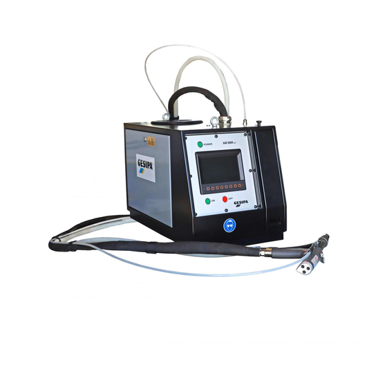
- Page 1 Automatic blind riveting system GAV-electronic Model 8000 Model 8000 eco fully automatic blind riveting system Year of manufacture ..Device no....
-
Page 2: Table Of Contents
- 1 - Table of Contents Table of Contents Chapter Page Dimension sheet, specifications and working area.…………………. Intended use and safety instructions.………………………………….. 5 - 6 Notes on environment, recycling, declaration of conformity.……… Transport and installation.………………………………………………... Commissioning and handling .…………………………………………... 9 - 10 Operational characteristics .………………………………………………... - Page 3 28.4 Process counter .…………………………………………………… 28.5 Selecting a profile list ………………………………………..…….. 28.6 Selecting a profile directly .………………………………………… 28.7 Selecting a profile step by step .………………………………….. 28.8 Evaluation process .………………………………………………... 28.9 Evaluation component .……………………………………………. 28.10 Other functions .…………………………………………….. not included in GAV-8000 eco...
- Page 4 - 3 - Table of Contents Table of Contents Spare parts list Overview subassemblies Spare parts list page Assembly 1: Pneumatic assembly .……………………………………….. 2 - 3 Assembly 2: Blind riveting gun……………………………………………. 4 - 10 Assembly 3: Hydraulic amplifier unit .……………………………………. 11 - 12 Assembly 4: Singulator ……………………………………………………...
-
Page 5: Dimension Sheet, Specifications And Working Area
- 4 - Dimension sheet, specifications and working area Standard tubing length: 3,5 meter (12,3ft) Feed unit Weight: 100 kg Volume remaining mandrel collecting basin: approx. 1800 – 5500 pieces (3.5 l) depending on size Electrics - Rated voltage: 230 Volt ~ 50 Hz - Rated current: <... - Page 6 - 4-R - Dimension sheet, specifications and working area Adapter - fastening - thread M10 Standard tubing length: 3,75 meter (12,3ft) Feed unit Weight: 100 kg Volume remaining mandrel collecting basin: approx. 1800 – 5500 pieces (3.5 l) depending on size Electrics - Rated voltage: 230 Volt ~ 50 Hz...
- Page 7 - 4-U- Dimension sheet, specifications and working area Feed unit Weight: 100 kg Volume remaining mandrel collecting basin: approx. 1800 – 5500 pieces (3.5 l) depending on size Electrics - Rated voltage: 230 Volt ~ 50 Hz - Rated current: <...
- Page 8 - 4-UA - 1-UA Dimension sheet, specifications and working area Standard tubing length: 3,75 meter (12,3ft) Feed unit Weight: 100 kg Volume remaining mandrel collecting basin: approx. 1800 – 5500 pieces (3.5 l) depending on size Electrics - Rated voltage: 230 Volt ~ 50 Hz - Rated current: <...
-
Page 9: Intended Use And Safety Instructions
- 5 - Intended use and safety instructions Intended use The blind riveting tool is intended exclusively for the processing of blind rivets suitable for use in automatic systems. Any other use or use beyond those limits will not be considered as intended. - Page 10 - 6 - Intended use and safety instructions Prevention of accidents Working with the GAV-8000 is only permitted for persons who have read and understood the operating and safety instructions (training!) have checked the device and the working area for hazards to life and limb before starting to work comply with accident prevention regulations do not wear their hair loose or loose fitting clothes or jewellery including rings (hazard of in-...
-
Page 11: Notes On Environment, Recycling, Declaration Of Conformity
- 7 - Notes on environment, recycling, Conformity declaration Notes on environment Noise of blind riveting plant Applied guidelines: 89/392/EWG Abl. EU Nr. L 183/9 3. GSGV machine noise information-VO DIN 45635 part 21 78/84 dB Permanent noise level: with/without conveyor unit ... -
Page 12: Transport And Installation
- 8 - Transport and installation Transport The blind riveting tool will be delivered and erected as agreed, or dispatched in a special wooden crate. Unpacked, the blind riveting tool can be moved on an even floor with the help of the trolley available under extras. -
Page 13: Commissioning And Handling
- 9 - Commissioning and handling Note! Prior to commissioning read, and comply with, the GAV operating instructions and safety instruc- tions. In addition, comply with occupational safety regulations. Commissioning Connecting the device to the compressed air supply network Use the pressure reducing valve 1-8002, to set Pressure the operating pressure to 6 bar;... - Page 14 - 10 - Commissioning and handling - The appropriate chuck jaws for each blind Chuck jaws riveting mandrel diameter are used. Chuck jaw scaling is as follows: Blind rivet mandrel diameter 1.5 to 2.1 mm 2.1 to 2.7 mm 2.7 to 3.3 mm 3.3 to 3.65 mm Oscillating conveyor bowl 6-8002 - The adjustable deflection sheet leading to...
- Page 15 - 11 - Sequence of operations The fully automatic blind riveting tool GAV-electronic comprises a feed unit and a handy blind riveting gun which are connected by a flexi-hose assembly. The feed unit comprises an electronic control with dialogue box, two hydraulic pressure trans- mitters, an electrical blind riveting conveyor unit and a remaining mandrel extractor with mandrel collecting basin.
-
Page 16: Description Of Functions
- 12 - Description of functions 7 Functional components of blind riveting gun The schematic diagrams and descriptions below show a simplified version of the extensive control and functional sequences. Expanding mouth piece - three-pieces - (1) Loading the blind rivet positioned in the gun head to processing position. Snap collet (2) carries out the unlocking and locking function of the expanding mouth piece (1). - Page 17 - 13 - Description of functions 7 Functional units of feed unit Blind rivet singulator (II) Part of blind riveting feed appliance. Here, the blind rivet (10) is separated and conveyed by compressed air through the conveying hose to the blind riveting gun. Pneumatic-hydraulic pressure transmitter (III) actuates the pressure piston (8);...
- Page 18 - 14 - Description of functions 7 Functional components of blind riveting gun Function image 1 The readjusting air interconnected by the valve (V) is waiting and keeps the complete piston unit (7/8) in back stop position. The snap collet (2) locks the segments of the expanding mouth piece (1) at their undercut.
- Page 19 - 15 - Description of functions 7 Function images and description Function image 3 The pulling piston (7) is being actuated by the pressure transmitter (IV) and moves to back stop position. When the valve is switched (V) the readjusting air escapes. This relieves the stop pis- tons (5) as well as the chuck jaw hose (4) and the chuck jaws (3) release the blind riveting man- drel (9).
- Page 20 - 16 - Description of functions 7 Function images and description Function image 5 The readjusting air is interconnected by the valve (V) and the pulling piston (7), as well as the piston of the pressure transmitter (IV), is reset at initial position. Simulteneously, the pressure piston (8) is actuated by the pressure transmitter (III) and carries out the unlocking stroke for the expanding mouth piece (1).
-
Page 21: Operation
- 17 - Operation 8.0 Overview 8000 Operating elements Graphic display Menu structure Main menu Error message Access management Manual Operation Setting parameters Selecting data 8.10 Text input... - Page 22 - 18 - Operation 8.1 Operational controls 1. POWER switch (main switch) Switches the supply voltage (230V/50Hz or 110V 60Hz). glowing green. 2. ON button activates various control functions (dependent on display menu). moves GAV into initial position. glowing green. 3.
- Page 23 - 19 - Operation 8.2 Graphic display Dialogue unit Graphic display The graphic display is part of the dialogue unit and allows interactive control of the GAV. The graphic display shows the status and parameters, issues messages and visualises internal processes.
- Page 24 Process data 20 days Process data day Process counter Process counter Operation data recording Operation data recording Access codes Access codes Time and language Time and language System info System info GRivCheck PC mode GESIPA GESIPA not included in GAV-8000 eco...
- Page 25 - 21 - Operation 8.4 Main menu After start-up and during normal operation the GAV will be in the main menu AUTO. AUTO main menu Status "Ready" Start option "manual" (man- ual release) Navigation: AUTO Title bar Status AUTO-OFF (press ON) GAV switched on (main switch “POWER”) Power to valves cut off.
- Page 26 - 22 - Operation 8.4 Main menu When the start-up conditions of the AUTO mode have been met, one of the active start-up op- tions (shown in title bar) can be used to trigger a cycle. The current tool status is shown on the title bar of the main menu.
-
Page 27: Settings Gav
- 23 - Operation 8.5 Error message Tool malfunctions are shown in the AUTO main menu by displaying a white text in a red box, whilst warning lights are blinking. Details of the causes of malfunctions can be found in the rele- vant menu of “settings GAV”. -
Page 28: Singulator
- 24 - Operation 8.5 Error message Submenu Error message Remedy Navigation Mouth piece Setting the small pressure transmitter WS3 ►MAN Expanding mouth piece of GAV - Press OFF button. ►Menu gun did not close. - Remove blind rivet. ►Settings GAV Press ON button. - Page 29 - 25 - Operation 8.5 Error message Direct menu selection: In order to simplify the search for the relevant menu containing information about the cause of the malfunction, and to use a shortcut, you can change the option in the main menu to the dis- played error message by using ? .
- Page 30 To enter an access code, an additional window appears in the relevant menu and the navigation bar is changed accordingly. The title bar of the window shows which access code must be en- tered, that is, the service or the GESIPA code. The access code is entered by using numbers to 4 .
- Page 31 - 27 - Operation 8.7 Manual mode The MAN menu allows GAV functions to be carried out manually. Malfunctions of the tool are shown in the same way as in the AUTO main menu but there are no start-up conditions. For reasons of safety all the active start options of the AUTO main menu are disabled for the entire manual area.
- Page 32 - 28 - Operation 8.8 Setting parameters Variable parameters are displayed and set the same way for all menus. Setting range and step sizes may be limited according to parameter and data type. High precision parameters have multi-step settings. For this, the whole number and decimal dig- its can be set in two steps, great values first in hundreds and then in unit digits.
- Page 33 The profile to be loaded can be selected in the window shown. The number of the se- lected profile and its alteration index is displayed on the status bar. This example shows features belonging to the process control function and is not included in the GAV-8000 eco.
- Page 34 - 30 - Operation 8. 10 Entering text Some menus require the input of text. An additional window appears for entering text and the navigation bar is changed accordingly. Which text input is expected is shown on the title bar of the window. The entered text and the number of characters still available are shown in the input line of the window.
-
Page 35: Blast Air
- 31 - Settings GAV 9.0 Overview Oscillating conveyor Pressure sensors Large pressure transmitter Small pressure transmitter Singulator Blast air Mandrel extractor Cycle Additional functions 9.10 Drive PLC 9.11 Permanent test 9.12 I/O-test 9.13 PLC interface test... - Page 36 - 32 - Settings GAV 9.1 Oscillating conveyor Menu settings oscillating conveyor Proximity switch NS1 Navigation: AUTO ► MAN ► Menu ► Settings GAV ► Oscillating conveyor Setting the oscillating conveyor (6-8000) (How to set the proximity switch NS1 4-8045 is described in chapter 9.5 “Settings GAV” – “singulator”) Conveying perform- controls the conveying performance of the oscillating conveyor.
- Page 37 - 33 - Settings GAV 9.2 Pressure sensors Menu settings Pressure sensor DS1/DS2 Navigation: AUTO ► MAN ► Menu ► Settings GAV ► Pressure sensors DS1 Network pressure (1-8040.1) monitors the compressed air supply of the GAV. (For settings see chapter 5 “Commissioning and handling”). Network max.
- Page 38 DS1/DS2 Navigation: AUTO ► MAN ► Menu ► Settings GAV ► Pressure sensors ► Cal GESIPA-Code Calibration DS1 (1-8040.1) Signal type Signal type of pressure sensor Measuring range Measuring range of pressure sensor Calibration DS2 (1-8040.2) Signal type Signal type of pressure sensor...
- Page 39 - 35 - Settings GAV Not included in GAV-8000 eco 9.2 Pressure sensors Calibration and basic setting pressure sensor DS3 (3-8192) The pressure sensor DS3 is adapted at the connection for the hydraulic line of the large pressure transmitter. The calibrating data for “signal type“, and “measuring range” in the “calibration pressure sensor DS3"...
- Page 40 ► Menu ► Settings GAV ► Large pressure transmitter GESIPA-Code WS1 shift points cycle (3-8197) The shift points control the sequences within the processing cycle. The setting range for this is the entire measuring range starting at the sensor's zero point.
- Page 41 Navigation: AUTO ► MAN ► Menu ► Settings GAV ► Large pressure transmitter ► Cal GESIPA-Code Calibration WS1 (3-8197) Signal type of distance sensor Signal type Measuring range of distance sensor Measuring range Zero point Zero point of distance sensor Restores standard settings.
- Page 42 - 38 - Settings GAV 9.3 Large pressure transmitter Menu settings Large pressure transmitter Distance sensor WS2 Navigation: AUTO ► MAN ► Menu ► Settings GAV ► Large pressure transmitter ► WS2 WS2 oil level (3-8198) monitors the oil level in the tank of the large pressure transmitter. Warning oil level max.
- Page 43 ► MAN ► Menu ► Settings GAV ► Large pressure transmitter ► WS2 ► Cal GESIPA-Code Calibration WS2 (3-8198) Signal type of distance sensor Signal type Measuring range of distance sensor Measuring range Zero point Zero point of distance sensor Restores standard settings.
- Page 44 - 40 - Settings GAV 9.4 Small pressure transmitter Menu settings Small pressure transmitter Distance sensor WS3 Navigation: AUTO ► MAN ► Menu ► Settings GAV ► Small pressure transmitter WS3 oil level (3-8199) monitors the oil level inside the small pressure transmitter. Warning oil level min.
- Page 45 Navigation: AUTO ► MAN ► Menu ► Settings GAV ► Small pressure transmitter ►Cal GESIPA-Code CalibrationWS3 (3-8199) Signal type of distance sensor Signal type Measuring range of distance sensor Measuring range Zero point of distance sensor Zero point Restores standard settings.
- Page 46 - 42 - Settings GAV 9.5 Singulator Basic setting proximity switch NS1 4-8045 Chute sheet (oscillating conveyor control) - Remove plug and detach locknut. - Set sensor flush with inner edge of chute sheet. - Tighten locknut and connect plug. Basic setting proximity switch NS2 4-8044 (Monitoring the singulator spoon) - Singulator closed in initial position.
- Page 47 - 43 - Settings GAV 9.6 Blast air Blast air Basic setting blast air regulating valve Open setting screw of the blast air regulating valve from locked position approx. 2 turns. Other settings: Less blast air due to damages by convey- ance on the blind rivet.
- Page 48 - 44 - Settings GAV 9.6 Blast air Initial setting central lubrication (1-8130) Setting screw upper stop position: Oil discharge per piston stroke near 0 Setting screw lower stop position: maximum oil discharge per piston lift. At this setting, the filling is empty after approx.
- Page 49 - 45 - Settings GAV 9.7 Mandrel extractor Basic setting Operating pressure mandrel extractor Activate mandrel extractor in the menu "MAN" using the function "mandrel extractor". At active mandrel extractor, set the pressure reducing valve mandrel extractor to 4 bar (flow pressure), check of manometer mandrel extractor.
- Page 50 - 46 - Settings GAV 9.7 Mandrel extractor Menu settings mandrel extractor Navigation: AUTO ► MAN ► Menü ► Settings GAV ► Mandrel extractor RS1 mandrel extractor (1-8041) registers torn off remaining mandrels. Malfunction mandrel extractor when set value for "remaining mandrel" is exceeded and set value for "running time"...
- Page 51 - 47 - Settings GAV 9.8 Cycle Menu settings cycle Navigation: AUTO ► MAN ► Menu ► Settings GAV ► Cycle Initial position ON “ON” function button from operating status "OFF". Initial position will be activated when the set value is reached Unlocking time Times in cycle monitors and controls times in cycle.
- Page 52 - 48 - Settings GAV 9.9 Additional functions Menu settings Additional functions Navigation: AUTO ► MAN ► Menu ► Settings GAV ► Additional functions Setting additional functions Manual trigger is locked whilst function is active. Lock manual trigger Manual trigger may be deactivated when additional start-up options were activated (foot-actuated triggering or drive PLC).
- Page 53 - 49 - Settings GAV 9.10 Drive PLC Menu settings Drive PLC Navigation: AUTO ► MAN ► Menu ► Settings GAV ► Drive PLC Setting the drive of PLC Condition: PLC interface connected (extra). With the f function active, the cycle is started via the Drive PLC PLC interface by the PLC (start-up option “PLC”).
- Page 54 - 50 - Settings GAV 9.11 Permanent test Permanent test can be used by the GAV to trigger processing cycles independently and at a set time or for a set piece number. It is possible to change to different menus during permanent test in order to observe statuses, sequences, parameter or settings.
- Page 55 - 51 - Settings GAV 9.12 I/O test The “I/O-test" menu shows all input and output statuses of the GAV. Output statuses may be changed independently from the current tool status. The values of the analogue sensors for distance and pressure are shown as absolute values, with the settings for “zero point”...
- Page 56 - 52 - Settings GAV 9.13 PLC interface test The input and output assignation of the PLC interface is displayed, and the connection of the GAV to the interface is tested in the PLC interface test menu. In addition it is possible to test in- dividual communications with a connected PLC or control and evaluation unit or input and mes- saging devices for each input and output.
- Page 57 - 52-UA - 9-UA Settings GAV 9.14-UA Proximity switch with pressure monitoring device Proximity switch 2-6001UA2 (pressure monitoring device ) Threaded pin Adjusting: Proximity switch-2-6001UA2 at operated pressure monitoring device to threaded pin easily close and approx. 1/4 then solve turn. Proximity switch with jam nut detent.
-
Page 58: Maintenance
- 53 - Maintenance 10.0 Overview 10.1 Service instructions 10.2 Maintenance messages... - Page 59 - 54 - Maintenance 10.1 Maintenance messages Attention! Follow safety instructions! Wear protective goggles! D a i l y: Grease Lubricate / replace chuck jaws. Turn off main switch “POWER“. Chuck case Unscrew expanding mouth piece 2-80. Pull off the snap collet 2-8022 and unscrew the chuck cage 2-8005 or 2-8205.
- Page 60 - 55 - Maintenance 10.1 Maintenance messages W e e k l y: Chute sheets Clean chute sheets. Clean gliding surfaces of chute sheets (do not use oil). As required: Oil rivet feed hose (Required after exchange of conveying hose or prolonged dry running) - Press “OFF”...
- Page 61 - 56 - Maintenance 10.2 Maintenance messages You can set maintenance intervals in the “maintenance” menu. All required maintenance work is then reported in the AUTO main menu. 8 different maintenance messages are available: 5 have fixed assignation (See chapter 10.1 “maintenance” – “notes on maintenance”) 3 may be assigned as you wish.
- Page 62 - 57 - Maintenance 10.2 Maintenance messages Example: In the example shown the maintenance message “grease chuck jaws“ is active, “counter” has reached the set value “message”. The relevant message is issued in the “AUTO“ main menu; the GAV does not stop. Work can continue until the maintenance has been carried out or con- firmed or until the "counter"...
-
Page 63: Functional Characteristics
- 58 - Process monitoring 11.0 Overview Not included in GAV-8000 eco 11.1 Functional characteristics 11.2 Adjustment 11.3 Create profile 11.4 Load profile 11.5 Store profile 11.6 Create profile list 11.7 Load profile list 11.8 Profile lists PLC... - Page 64 Process monitoring 11.1 Functional characteristics Not included in GAV-8000 eco The setting process of the GAV is monitored by recording tensile distance and force during blind rivet processing, followed by an evaluation of the tear off point (tear off distance and tear off force).
- Page 65 - 60 - Process monitoring 11.2 Setting Not included in GAV-8000 eco Denomination Process graph Process evaluation Current profile Next profile The following details for setting process monitoring are shown in the AUTO main menu: Designation: The denomination of the current profile list is displayed. If no profile list is active, the denomina- tion of the current profile will be displayed.
- Page 66 - 61 - Process monitoring Not included in GAV-8000 eco 11.2 Setting Settings Process monitoring Navigation: AUTO ► MAN ► Menu ► Process monitoring In the “setting process monitoring“ menu - the current process graph is displayed in detail, including the scaling of tensile distance and force.
- Page 67 - 62 - Process monitoring Not included in GAV-8000 eco 11.3 Creating a profile Starting position AUTO main menu After the start-up of the GAV the profile used last will be loaded automatically. If no profile was created so far, a profile called “start profile”...
- Page 68 - 63 - Process monitoring 11.3 Creating a profile Not included in GAV-8000 eco Step 2: Enter denomination and item number First enter the denomination of the profile and then the item number for the blind rivet. denomination profile should...
- Page 69 - 64 - Process monitoring 11.3 Creating a profile Not included in GAV-8000 eco When cycle is selected, at least 3 blind rivets will be processed jointing stock. The tear off point of the current process graph turns blue and those of the last maximal 20 processes are displayed in grey.
- Page 70 - 65 - Process monitoring 11.3 Creating a profile Not included in GAV-8000 eco Step 5: Setting scaling for tensile distance The scaling for the tensile distance is to be set in such a way that the target value for the tear off point lies at approx.
- Page 71 - 66 - Process monitoring 11.3 Creating a profile Not included in GAV-8000 eco After the profile was stored, the new parameters will be imported automatically… ...and after returning to the main menu they will be activated as individual profile.
- Page 72 - 67 - Process monitoring Not included in GAV-8000 eco 11.4 Loading a profile From the AUTO main menu by pressing ► MAN ► Menu ► Process control ► Profile go to the “setting profile” menu evaluation parameters of the current profile are displayed.
- Page 73 - 68 - Process monitoring Not included in GAV-8000 eco 11.5 Storing a profile From the AUTO main menu by pressing ► MAN ► Menu ► Process monitoring ► Profile go to the “setting profile” menu. The evaluation parameters of...
- Page 74 - 69 - Process monitoring 11.5 Storing a profile Not included in GAV-8000 eco Use ..as (save as) to store the current profile with a new denomination item number. To add a new denomination and item number you can either change the original...
- Page 75 - 70 - Process monitoring Not included in GAV-8000 eco 11.6 Creating a profile list Starting position AUTO main menu After start-up the GAV loads first the profile or profile list used most recently as well as the profile used most recently in it.
- Page 76 - 71 - Process monitoring 11.6 Creating a profile list Not included in GAV-8000 eco Step 2: Enter denomination and item number First enter the denomination of the profile list and then the item number component part sub- assembly. denomination...
- Page 77 - 72 - Process monitoring 11.6 Creating a profile list Not included in GAV-8000 eco Now the profiles can be selected in the required order and then stored to the profile list by using A new profile list is created by...
- Page 78 - 73 - Process monitoring 11.6 Creating a profile list Not included in GAV-8000 eco After completion the new profile list and the first profile are automatically loaded from In the example shown, a Jointing Profile no. Profile Blind rivet...
- Page 79 - 74 - Process monitoring Not included in GAV-8000 eco 11.7 Loading a profile list From the AUTO main menu by pressing ► MAN ► Menu ► Process control ► Profile ► List go to the “setting profile” menu. Profiles of the current profile list or the profile list used most recently are shown.
- Page 80 - 75 - Process monitoring Not included in GAV-8000 eco 11.8 Profile lists PLC From the AUTO main menu by pressing ► MAN ► Menu ► Process control ► Profile ► List ► PLC go to the “setting profile lists PLC”...
-
Page 81: Process Control Calibration
- 76 - Process Control Not included in GAV-8000 eco 11.9 Menu Calibration process monitoring Menu Calibration process monitoring Navigation: AUTO ► MAN ► Menu ► Process control ► Cal Overview of the latest calibration operations: Date, Time Time record of the terminated calibration operations... - Page 82 - 77 - Process Control Not included in GAV-8000 eco 11.9.1 Calibration force Menu Calibration force Navigation: AUTO ► MAN ► Menü ► Process Control ► Cal ► Force Perform the calibration process: Enter the breakload of the calibration mandrels (see. Label of calibration mandrels...
- Page 83 - 78 - Process Control Not included in GAV-8000 eco 11.9.2 Calibration path Menu: Calibration path Navigation: AUTO ► MAN ► Menu ► Process Control ► Cal ► Path Performing the calibration: When Improve WS1 Adjustment ! is displayed, then adjust the initial position of the stroke sensor WS1 according to the proposed value and direction (see also chapter 9.3...
-
Page 84: Process Data
- 79 - Process data Not included in GAV-8000 eco After each setting process the following parameters are stored in the process data file: Date and time (time stamp) Profile and profile list used for evaluation Tear off distance and tear off force (tear off point) ... -
Page 85: Process Counter
- 80 - Process counter The process counter can be applied to determine per component part the number of blind rivets to be processed and to display and monitor in the AUTO main menu their processing by count- ing. This function cannot be used simultaneously with another profile list. The installation of the required component parts is described in chapter 28.4 “PLC interface –... -
Page 86: Access Codes
Service and GESIPA code may be changed in the “access codes” menu: To change service or GESIPA code, the relevant access authorization has to be given. Afterwards the new code is entered twice. If both inputs are identical, the new code will be stored. -
Page 87: Time And Language
► MAN ► Menu ► System time GESIPA-Code System time is mainly required for the time stamp of the data record in the area of setting proc- ess monitoring and operating data collection. To simplify file collating (e.g. process and operating data) from different time zones, it is advis-... -
Page 88: System Info
- 83 - System information System information Navigation: AUTO ► MAN ► Menu ► System information Apart from the current system time and the counter status of the electronic counter important in- ternal system parameters are displayed in the “system info“ menu. ... -
Page 89: Grivcheck
- 84 - GRivCheck Not included in GAV-8000 eco The connection between the dialogue units of the GAV and the PC with the user software GRivCheck is prepared via the interface RS232 in the “GRivCheck” menu and communication is displayed according to connection structure. Connection can take place directly between PC and GAV or via the PLC interface. - Page 90 - 85 - Malfunction supply unit GAV not triggered (“AUTO“, main menu, no error message) Cause/reason Remedy Relevant trigger option not selected or dis- Select trigger option, see chapter 9.9 “settings abled. GAV” – “additional functions”. Pressure sensor DS2 1-8040.2 set incorrectly. Set pressure sensor DS2 1-8040.2, see chap- ter 9.2 "settings GAV"...
- Page 91 - 86 - Malfunction blind riveting gun Follow safety and environmental instructions! Wear protective goggles! Attention! Always cut off compressed air supply from the tool and turn off main switch before unscrewing the expanding mouth piece or the expanded mouth piece. Blind rivet not conveyed from expanding mouth piece or mouth piece not closing.
- Page 92 - 87 - Malfunction blind riveting gun Blind rivet conveyed too far out of the expand- ing mouth piece. Press OFF button. Remove blind rivet Press ON button. Carry out “cycle“ function in “MAN“ menu. Cause/reason Remedy Maintenance of chuck jaws required, see chapter 10.1 “notes on maintenance”...
- Page 93 - 88 - Malfunction blind riveting gun Blind rivet does not arrive in blind riveting gun Carry out “cycle“ function in “MAN“ menu. Cause/reason Remedy Loosen and remove wedged blind rivet by Blind rivet wedged in rivet feed hose. kinking the rivet feed hose. To open singulator 4-8000, select “open singu- lator“...
- Page 94 - 89 - Malfunction blind riveting gun Two blind rivets in expanding mouth piece. Press OFF button. Remove blind rivet Press ON button. Carry out “cycle“ function in “MAN“ menu. Cause/reason Remedy Set singulator tongue 4-8007 in such a way Incorrect setting singulator tongue 4-8007.
-
Page 95: Repair Instructions Blind Rivetting Gun
- 90 - Repair instructions blind riveting gun Follow safety and environmental instructions! Wear protective goggles! Attention! Turn off main switch and compressed air supply to tool! Replacing the locking spring 2-33 - Unscrew expanding mouth piece 2-80. - Detach snap collet 2-22. - Pull out locking spring 2-33 from the catch. - Page 96 - 91 - Repair instructions blind riveting gun Replace chuck jaw hose 2-6032. Unscrew expanding mouth piece 2-80. Detach snap collet 2-22. Unscrew the feed mechanism. Pull out chuck jaw hose 2-6032 from catch. Attention! To prevent damage to the leaf spring, assemble the chuck jaw hose according to pos.
- Page 97 - 92 - Repair instructions blind riveting gun Replacing the blind riveting gun Turn off main switch and compressed air supply to tool. Disconnect rivet feed hose, air guide hose as well as hydraulic control hose from blind riveting gun. Unscrew ventilating screw 2-28a, lift blind riveting gun above level of pressure transmitter tank.
- Page 98 - 93 - Repair instructions blind riveting gun Replacing the piston unit 2-6190 Mounting aids: Mounting cone E9-18 (extra) Mounting bolt E9-21 (extra) Punch E9-22 (extra) Removal: Detach expanding mouth piece 2-80 and snap collet 2-22. Unscrew cover 2-2 and thread plug 2-6003. Turn back stop ring 2-6021 (pre-tensed) by approx.
- Page 99 - 94 - Disassembling and assembling The pressure transmitter Follow safety and environmental instructions! Wear protective goggles! Attention! It is of utmost importance that you disconnect the tool from the power and compressed air supply! Large pressure transmitter 3-8060 Screw plug Remove right and left cover and the mandrel collector from the case.
- Page 100 - 95 - Disassembling and assembling the pressure transmitter Small pressure transmitter 3-8030 Remove left-hand cover from housing. Place a cloth below the hydraulic control hose before disconnecting the plug-connection to the distance sen- sor and the hose connections so that any escaping oil is caught.
-
Page 101: Repair Instructions Pressure Transmitter
- 96 - Repair instructions pressure transmitter Follow safety instructions! Wear safety goggles! Replacing the pressure spring 3-8098 in large pressure transmitter 3-8060 Disassemble the pressure transmitter 3-8060 (see chapter 22 “disassembling and assembling the pressure transmitter”) Via boring in the cover lid 3-8073 suck off hydraulic oil in the legally admitted oil tank and remove it according to the envi- ronmental laws. - Page 102 - 97 - Repair instructions pressure transmitter Pressure sensor DS3 Distance sensor WS2 3-8192 3-8198 Cover lid Distance sensor WS1 3-8197 3-8073 Vertical bolt Washer 3-8102 3-8077 Inspection glass Pressure spring 3-8075 3-8099 Lock nozzle Cylinder sealing 3-8068 3-8081 Valve plate Throttle cylinder 3-8067 3-8079...
-
Page 103: Filling Hydraulic Systems
- 98 - Filling hydraulic systems Follow safety and environmental instructions! Wear safety goggles! Hydraulic system for blind riveting process large pressure transmitter 3-8060 Assembly aid: Ventilating check valve E9-7 (extra) Close both throttle sound absorbers 3-8082 on the valve block leaving one rotation undone. Turn on main switch and select “MAN”... - Page 104 - 99 - Filling hydraulic systems Hydraulic system for mouth piece release small pressure transmitter 3-8030 Unscrew the front ventilating screw 2-28b on the gun. Note! To achieve faultless ventilation, place the blind riveting gun in such a way that the hose assembly is ascending from the supply unit to the blind riv- eting gun.
-
Page 105: Replacing Control Components
- 100 - Replacing control components Follow safety instructions! Attention! It is of utmost importance that you disconnect the tool from the power and compressed air supply! - Detach 8 screws on front plate and carefully take off front plate. - Detach 2 cable connections from frontplate to tool. -
Page 106: Pneumatic Connection Diagram
- 101 - Pneumatic connection diagram integrated... - Page 107 - 102 - Electric circuit diagram...
- Page 108 - 103 - Electric circuit diagram...
-
Page 109: Plc Interface
- 104 - PLC interface 28.0 Overview 28.1 Technical description 28.2 PLC interface test 28.3 Drive PLC 28.4 Process counter 28.5 Select profile list 28.6 Selecting a profile (directly) 28.7 Selecting a profile (step by step) 28.8 Evaluation process 28.9 Evaluation component part 28.10 Other functions... - Page 110 - 105 - PLC interface 28.1 Specifications The PLC interface serves as an interface to an external PLC, an external control and answer unit or to external input or message devices and enables the connection of a notebook / PC with suitable PC software.
- Page 111 - 106 - PLC interface 28.1 Specifications Technical data Dimensions approx. 205 mm x 128 mm x 50 mm Weight approx. 460 g Fitting on mounting rail NS 35 x 7.5 (top hat rail) Operative voltage 24V DC (permitted voltage range 20 - 30V DC) Interface: approx.
- Page 112 - 107 - PLC interface 28.1 Specifications Pin assignment PLC interface 24V DC for 16 Outputs 6 relay Outputs Outputs - - + + 1 2 3 4 5 6 7 8 9 10 11 12 13 14 15 16 GSPS-IF PC (USB) 1 2 3 4 5 6 7 8 9 10 11 12 13 14 15 16...
- Page 113 - 108 - PLC interface 28.2 PLC interface test The input and output assignation of the PLC interface is displayed, and the connection of the GAV to the interface is tested in the PLC interface test menu. In addition it is possible to test in- dividual communications with a connected PLC or control and evaluation unit or input and mes- saging devices for each input and output.
- Page 114 - 109 - PLC interface 28.3 Drive PLC Drive PLC Navigation: AUTO ► MAN ► Menu ► Settings GAV ► PLC interface test System requirements: PLC interface connected to GAV. PLC connected to PLC interface. Drive PLC active. AUTO► MAN► menu► settings GAV► drive PLC. Inputs: Input 1 “start cycle“...
- Page 115 - 110 - PLC interface 28.3 Drive PLC The flow chart shows a typical communication of a GAV8000 via PLC interface with the PLC of a device. In this example the GAV gun is mounted axially mobile on the conveying slide of a de- vice, that has two stop positions, approx.
- Page 116 - 111 - PLC interface 28.4 Process counter Prozess counter Navigation: AUTO ► ► Menu ► Settings GAV ► PLC interface test System requirements: PLC interface connected to GAV. Process counter active (see chapter 13 “process counter“). No process list active (see chapter 11 “process monitoring“). Inputs: With rising edge on output 5 “counter start”...
- Page 117 - 112 - PLC interface 28.5 Select profile list Not included in GAV-8000 eco Select profile list Navigation: AUTO ► ► Menu ► Process monitoring ► Profile ► List ► ► Test System requirements: PLC interface connected to GAV.
- Page 118 - 113 - PLC interface 28.6 Selecting a profile directly Not included in GAV-8000 eco Selecting profile directly Navigation: AUTO ► ► Menu ► Settings GAV ► PLC interface test System requirements: PLC interface connected to GAV. Process monitoring and profile list active (see chapter 11 “process monitoring“).
- Page 119 - 114 - PLC interface 28.7 Selecting a profile step by step Not included in GAV-8000 eco Selecting profile step by step Navigation: AUTO ► ► Menu ► Settings GAV ► PLC interface test System requirements: PLC interface connected to GAV.
-
Page 120: Evaluation Process
- 115 - PLC interface 28.8 Evaluation process Not included in GAV-8000 eco Evaluation process Navigation: AUTO ► ► Menu ► Settings GAV ► PLC interface test System requirements: PLC interface connected to GAV. Process monitoring and profile list active (see chapter 11 “process monitoring“). -
Page 121: Evaluation Component
- 116 - PLC interface 28.9 Evaluation component part Not included in GAV-8000 eco Evaluation component part Navigation: AUTO ► ► Menu ► Settings GAV ► PLC interface test System requirements: PLC interface connected to GAV. Process monitoring and profile list active (see chapter 11 “process monitoring“). -
Page 122: Other Functions
- 117 - PLC interface 28.10 Other functions Other functions Navigation: AUTO ► ► Menu ► Settings GAV ► PLC interface test Inputs: Input 4 “lock cycle start”. Input 4 “lock cycle start” at 1 (24V) can be used in “AUTO” MODE, to lock all trigger options (manual, foot, PLC etc). - Page 123 Automatic blind riveting system GAV-electronic Model 8000 Model 8000 eco Spare parts and extras...
- Page 124 - 1 - Spare parts Assembly overview 2-UA Assembly no. Designation Page Pneumatics - control block Blind riveting gun standard - 11 robotic 5-R - 11-R type U 5-U - 11-U 2-UA type U with pressure monitoring device 5-UA - 11-UA Hydraulics - amplifier unit 12 - 13 Singulator...
- Page 125 - 2 - Spare parts E 1 pneumatic assembly 32.2 33.2 33.1 32.1 40.1 40.2 57.1...
- Page 126 - 3 - Spare parts E 1 pneumatic assembly Item Part No. Article No. Designation 1-8002 719 1243 Maintenance unit (without 8028) 1-8003 719 1294 Pressure tank (without 8045 / 8048) 1-8012 719 1359 Banjo bolt 1-8015 719 1112 Sealing plate 1-8016 719 5559 Twin vent valve...
- Page 127 - 4 - Spare parts E2 Blind riveting gun 161-168 171-175 6022 261-268 271-275 27.3 27.4 80/.. 80/..F 27.2 27.5...
- Page 128 - 4-R - E2-R Spare parts E2-R Blind riveting gun robotic...
- Page 129 - 4-U - E2-U Spare parts E2-U Blind riveting gun type U...
- Page 130 - 4-UA - E2-UA Spare parts E2-U Blind riveting gun type U with pressure monitoring device...
- Page 131 - 4-V - E2-V Spare parts E2-V Blind rivetting gun type V...
- Page 132 - 5 - Spare parts E2 Blind riveting gun...
- Page 133 - 5-R - E2-R Spare parts E2-R Blind riveting gun robotic...
- Page 134 - 5-U - E2-U Spare parts E2-U Blind rivetting gun type U...
- Page 135 - 5-UA - E2-UA Spare parts E2-U Blind riveting gun type U with pressure monitoring device...
- Page 136 - 5-V - E2-V Spare parts E2-V Blind rivetting gun type V...
- Page 137 - 6 - Spare parts E2 Blind riveting gun Item Part No. Article No. Designation 2-6000 719 9465 Blind riveting gun assembly 2-6001 719 0921 Case assembly 2-0002 719 2029 Cover 2-6003 719 0913 Thread plug 2-6205 719 9201 Chuck cage 36° (denomination: 1 ring) 2-6005 719 1626 Chuck cage 28°...
- Page 138 - 6-R - E2-R Spare parts E2-R Blind riveting gun robotic Articel-No. Part No. Discription 719 1642 GAV 2 - 6000R blind riveting tool, complete 719 4765 GAV 2 - 6000R/1 sealing set 719 4641 GAV 2 - 6001R 1 holding fixture 719 4668 GAV 2 - 6001R 2...
- Page 139 - 6-U - E2-U Spare parts E2-U Blind rivetting gun type U Article-No. Part-No. Discription 719 0182 2 – 6000U blind riveting tool, complete 719 7535 2 – 6001U housing complete 719 7667 2 – 6001U7 screw in connection 719 2029 2 - 2 cover 719 0913...
- Page 140 - 6-UA - E2-UA Spare parts E2-U Blind riveting gun type U with pressure monitoring device Article-No. Part-No. Discription 719 1074 2 – 6000UA blind riveting tool, complete 719 1012 2 – 6001UA housing complete 719 1077 2 – 6001UA1 handle 719 1068 2 –...
- Page 141 - 6-V - E2-V Spare parts E2-V Blind rivetting gun type V Article-No. Part-No. Discription 719 0174 2 – 6000V blind riveting tool, complete 719 5923 2 – 6001.1V housing complete 719 2029 2 - 2 cover 719 0913 2 - 6003 threaded plug 719 9201 2 - 6205...
- Page 142 - 7 - Spare parts E2 Blind riveting gun Item Part No. Article No. Designation 2-6032 719 9449 Chuck jaw hose 2-33 719 2339 Locking spring 33 B 2-33 B 719 0506 Locking spring (9mm shorter) 33 C 2-33 C 719 0654 Locking spring (90°...
- Page 143 - 7-R - E2-R Spare parts E2-R Blind rivetting gun robotic Article-No. Part No. Discription GAV 2 - 6030 719 0638 jaw closing tube bushing compl. with Part No.56 GAV 2 - 6031 719 0875 stop sleeve 719 9457 GAV 2 - 6031.1 stop sleeve shortened by 2 mm...
- Page 144 - 7-U - E2-U Spare parts E2-U Blind rivetting gun type U Article-No. Part-No. Discription 719 9449 2 - 6032 jaw closing tube 719 2339 2 - 33 retaining spring 719 0506 2 - 33 B retaining spring (9mm shortened) 719 0654 2 - 33 C retaining spring (90°...
- Page 145 - 7-UA - E2-UA Spare parts E2-U Blind rivetting gun type U with pressure monitoring device Article-No. Part-No. Discription 719 9449 2 - 6032 jaw closing tube 719 2339 2 - 33 retaining spring 719 0506 2 - 33 B retaining spring (9mm shortened) 719 0654 2 - 33 C...
- Page 146 - 7-V - E2-V Spare parts E2-V Blind rivetting gun type V Article-No. Part-No. Discription 719 9449 2 - 6032 jaw closing tube 719 2339 2 - 33 retaining spring 719 0506 2 - 33 B retaining spring (9mm shortened) 719 0654 2 - 33 C retaining spring (90°...
- Page 147 - 8 - Spare parts E2 Blind riveting gun Item Part No. Article No. Designation 69 2-6069 719 0840 Valve piston assembly with part no. 6079 and +6094 70 2-6070 719 0832 Jumper ring 71 2-6071 719 0824 Support ring 72 ...
- Page 148 - 8-R - E2-R Spare parts E2-R Blind rivetting gun robotic Article-No. Part No. Discription 2 - 6069 valve rod compl. with Part No. 6079 + 609 719 0840 2 - 6070 719 0832 connectionsring 2 - 6071 719 0824 bearing ring 2 - 6072 ...
- Page 149 - 8-U - E2-U Spare parts E2-U Blind rivetting gun type U Article-No. Part No. Discription 2 - 6069 valve rod compl. with Part No. 6079 + 609 719 0840 2 - 6070 719 0832 connectionsring 2 - 6071 719 0824 bearing ring 2 - 6072 ...
- Page 150 - 8-UA - E2-UA Spare parts E2-U Blind rivetting gun type U with pressure monitoring device Article-No. Part No. Discription 2 - 6069 valve rod compl. with Part No. 6079 + 609 719 0840 2 - 6070 719 0832 connectionsring 2 - 6071 ...
- Page 151 - 8-V - E2-V Spare parts E2-V Blind rivetting gun type V Article-No. Part No. Discription 2 - 6069 valve rod compl. with Part No. 6079 + 609 719 0840 2 - 6070 719 0832 connectionsring 2 - 6071 719 0824 bearing ring 2 - 6072 ...
- Page 152 - 9 - Spare parts E2 Blind riveting gun Boring Ø Item Part No. Article No. Designation 80/ 16 719 0395 80/ 18 719 2827 80/ 20 719 2800 80/ 23 719 2835 80/ 27 719 2878 Expanding mouth piece assembly 80/..
- Page 153 - 10 - Spare parts E2 Blind riveting gun Rivet man- Article Partition drel Item Part No. Designation 2-6161 719 0735 1.25 1.5 - 2.0 2-6162 719 1448 Chuck jaws 1.25 2.1 - 2.6 3-piece / 28º 2-6163 719 1545 1.25 2.7 - 3.2 2-6164...
- Page 154 719 2014 Pressure sensor 3-8197 719 1128 Distance sensor 1 fully equipped 3-8198 719 2019 Distance sensor 2 fully equipped 3-8199 719 1129 Distance sensor 3 fully equipped 717 1757 Hydraulic oil 250 cm³ not included in GAV-8000 eco nicht enthalten...
- Page 155 - 12 - Spare parts E3 Hydraulics - amplifier unit Item Part No. Article No. Designation 60.1 Pressure transmitter (without accessories) 60.0 Pressure transmitter - sealing 3-8063 719 2058 Flange 3-8064 719 4536 Cylinder hose 3-8065 719 4609 Transmitter piston 3-8067 719 4579 Valve plate assembly...
- Page 156 - 13 - Spare parts E4 singulator Item Part No. Article No. Designation 4-8000 719 6512 Singulator assembly 4-8002 719 4021 Spoon assembly 4-8007 719 4072 Singulator tongue 4-8008 719 4080 Collar screw 4-8011 719 4110 Spacer ring 4-8013 719 4137 Pressure spring 4-8125 719 4250...
- Page 157 - 14 - Spare parts E5 Case unit Item Part No. Article No. Designation 5-8000 719 0100 Case unit assembly 5-8002 719 6539 Container 5-8008 719 3904 Cover assembly 5-8026 719 5370 Lock...
- Page 158 - 15 - Spare parts E6 osciallating conveyer unit Item Part No. Article No. Designation 719 6555 230V / 50Hz 6-8000 Oscillating conveyor unit assembly 719 6563 115V / 60Hz 719 6571 230V / 50Hz 6-8001 Oscillating conveyor drive 719 6598 115V / 60Hz 719 6601 230V / 50Hz...
- Page 159 - 16 - Spare parts E7 feed bundle 20-26 Item Part No. Article No. Designation 7-8001.1 719 1162 Feed bundle without rivet feed hose 7-8002.2 719 1170 Feed bundle without rivet feed hose SL. . . m Rivet feed hose assembly 6 / 3.8 m 7-8020 719 6830 Rivet feed hose assembly 8 / 3.8 m...
- Page 160 - 17 - Spare parts E8 control Item Part No. Article No. Designation 8-8001 719 2008 Control module with 24 E/A 8-8002 719 2012 Control power pack 24VDC 2.5 A 8-8004 719 2017 Electronic module 1x 8-8005 719 2018 Electronic module 2x 8-8007 719 2007 Electronic module oscillating conveyor control...
- Page 161 - 17-UA - E8-UA Spare parts E8.1-UA Proximity switch Pos. Part No. Article-No. Discription 8-8104 719 1069 Sensorcable, komplete...
- Page 162 - 18 - Spare parts E9 accessories Item Article No. Designation 719 9015 Balancer for riveting gun 719 9031 GAV carriage with extension arm 719 9074 Ventilation check valve 719 9082 Rivet guns - support unit 719 9198 Mounting cone for piston unit 719 5583 Assembly tool for lip seal 719 6687...
- Page 163 - 19 - Spare parts E9 assembly tools...
- Page 164 - 20 - Spare parts front plate E10 front plate Item Part No. Article No. Designation 10-8000 719 0065 Front plate assembly 10-8005 719 2009 Process and dialogue display assembly with fixing set 10-8040 719 0630 Set of screws 10-8047 719 1120 Push button assembly POWER green 10-8048...
- Page 165 - 20 - Spare parts front plate E10 front plate eco Item Part No. Article No. Designation 10-8100 719 0105 Front plate assembly 10-8105 719 1996 Process and dialogue display assembly with fixing set 10-8040 719 0630 Set of screws 10-8047 719 1120 Push button assembly POWER green...
- Page 166 - 21 - Spare parts cable tree E11 cable tree Item Part No. Article No. Designation Cable tree assembly...
- Page 167 - 22 - Spare parts cable tree E11 cable tree Item Part No. Article No. Designation Cable tree assembly...
- Page 168 - 23 - Spare parts cable tree E11 interface cable Item Part No. Article No. Designation Interface cable assembly...
Need help?
Do you have a question about the 8000 eco and is the answer not in the manual?
Questions and answers