Table of Contents
Advertisement
Quick Links
Quick Installation Guide
Moxa Remote Connect Gateway
Moxa Americas:
Toll-free: 1-888-669-2872
Tel:
1-714-528-6777
Fax:
1-714-528-6778
Moxa Europe:
Tel:
+49-89-3 70 03 99-0
Fax:
+49-89-3 70 03 99-99
Moxa India:
Tel:
+91-80-4172-9088
Fax:
+91-80-4132-1045
MRC-1002 Series
Edition 3.0, September 2020
Technical Support Contact Information
www.moxa.com/support
2020 Moxa Inc. All rights reserved.
Moxa China (Shanghai office):
Toll-free: 800-820-5036
Tel:
+86-21-5258-9955
Fax:
+86-21-5258-5505
Moxa Asia-Pacific:
Tel:
+886-2-8919-1230
Fax:
+886-2-8919-1231
P/N: 1802010020013
*1802010020013*
Advertisement
Table of Contents

Related Manuals for Moxa Technologies MRC-1002 Series


Summary of Contents for Moxa Technologies MRC-1002 Series
- Page 1 MRC-1002 Series Quick Installation Guide Moxa Remote Connect Gateway Edition 3.0, September 2020 Technical Support Contact Information www.moxa.com/support Moxa Americas: Moxa China (Shanghai office): Toll-free: 1-888-669-2872 Toll-free: 800-820-5036 Tel: 1-714-528-6777 Tel: +86-21-5258-9955 Fax: 1-714-528-6778 Fax: +86-21-5258-5505 Moxa Europe: Moxa Asia-Pacific:...
-
Page 2: Package Checklist
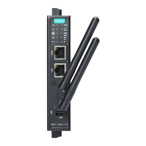
Overview The MRC-1002 Series is the gateway part of the Moxa Remote Connect Solution, which connects remote Ethernet-based industrial equipment to the Moxa Remote Connect Server. This allows service engineers to access the equipment on the local network remotely. Package Checklist... -
Page 3: Led Indicators
LED Indicators Color Function Symbol Name Green Steady On: The USB device is connected and working Steady Off: The USB device is not connected Power Green Steady On: The gateway is powered on Steady Off: The gateway is powered off Internet Green Blinking: Testing the Internet connectivity... - Page 4 Mounting Dimensions (unit: mm [inch]) DIN-rail mounting Wall-mounting - 4 -...
-
Page 5: Wiring Requirement
Installing the MRC-1002 Gateway The metal DIN-rail kit is fixed to the back panel of the MRC-1002 gateway when you take it out of the box. Mount the MRC-1002 gateway on corrosion-free mounting rails that meet the EN 60715 standard. STEP 1: Click on the DIN rail and push down into the mounting rail. - Page 6 ATTENTION Safety First! Be sure to disconnect the power cord before installing and/or wiring your MRC-1002 gateway. Calculate the maximum possible current in each power wire and common wire. Observe all electrical codes dictating the maximum current allowable for each wire size. If the current goes above the maximum rating, the wiring could overheat, causing serious damage to your equipment.
- Page 7 Wiring the Relay Contact The MRC-1002 Series has one relay output. This relay contact uses two contacts of the terminal block on the bottom panel of the MRC-1002 gateway. Refer to the next section for detailed instructions on how to connect the wires to the terminal block connector, and how to attach the terminal block connector to the terminal block receptor.
- Page 8 Wiring the Serial Ports The MRC-1002 gateway has one serial port. Each port can be configured by software for RS-232, RS-422, or RS-485. The pin assignments for the ports are shown in the following table. RS-232 RS-422 RS-485 TXD+ – TXD- –...
- Page 9 USB Port The USB 2.0 port (type A connector) is located at the lower part of the front panel, and supports a USB storage device driver for FAT, FAT32 and NTFS. The pinout of the USB port is as below. Description VCC (+5V) D- (Data-)
-
Page 10: Reset Button
Reset Button The MRC-1002 gateway has a reset button on the top of the panel. Push down the button with a pin and the gateway will reset to default. Pressing and releasing the button for different durations has different actions as listed below. Operation LED (Blinking) Action... -
Page 11: Warranty
• -30 to +3 V for state “0” • Max. input current: 8 mA Environmental Limits Operating Temperature Standard models: -10 to 60°C (-14 to 140°F) Wide temperature models: MRC-1002-T: -40 to 75°C (-40 to 167°F) MRC-1002-LTE-XX-T Series: -30 to 70°C (-22 to 158°F) Storage Temperature -40 to 85°C (-40 to 185°F)
Need help?
Do you have a question about the MRC-1002 Series and is the answer not in the manual?
Questions and answers