Moxa Technologies MGate MB3000 Series User Manual
Modbus gateway
Hide thumbs
Also See for MGate MB3000 Series:
- User manual (88 pages) ,
- User manual (84 pages) ,
- User manual (89 pages)

Related Manuals for Moxa Technologies MGate MB3000 Series


Summary of Contents for Moxa Technologies MGate MB3000 Series
- Page 1 MGate MB3000 Modbus Gateway User Manual Version 13.3, May 2024 www.moxa.com/products © 2024 Moxa Inc. All rights reserved.
- Page 2 MGate MB3000 Modbus Gateway User Manual The software described in this manual is furnished under a license agreement and may be used only in accordance with the terms of that agreement. Copyright Notice © 2024 Moxa Inc. All rights reserved. Trademarks The MOXA logo is a registered trademark of Moxa Inc.
-
Page 3: Table Of Contents
Table of Contents Introduction ............................5 Overview .............................. 5 Package Checklist ..........................6 Product Features ........................... 6 Getting Started ............................. 7 Connecting Power ..........................7 Connecting Serial Devices ........................7 RS-485 Termination and Pull High/Low Resistors ................8 Connecting to a Host or the Network ....................8 Installing the Software ........................ - Page 4 Change Language Setting ......................38 Connecting to the Unit .......................... 39 Broadcast Search ......................... 40 Specify IP Address ........................41 Changing the Configuration ........................43 Password Protection........................43 Basic Settings ..........................44 Network Settings .......................... 45 Serial Settings ..........................46 Protocol Settings ..........................
-
Page 5: Introduction
1. Introduction Welcome to the MGate MB3000 line of Modbus gateways. All models feature easy integration of Modbus TCP to Modbus RTU/ASCII and feature RS-232/422/485 ports for Modbus serial communication. One-, two-, and four-port models are available. This user’s manual applies to the following models: •... -
Page 6: Package Checklist
Package Checklist All models in the MGate MB3000 line are shipped with the following items: Standard Accessories 1 MGate MB3000 Modbus gateway • Quick installation guide (printed) • Power adapter (MB3180, MB3280, and MB3480 only) • Warranty card • Optional Accessories DK-35A: DIN-rail mounting kit (35 mm) •... -
Page 7: Getting Started
2. Getting Started This chapter provides basic instructions for installing the MGate MB3000. Connecting Power The unit can be powered using the AC adaptor or by connecting a power source to the terminal block, depending on the model. The following instructions are for the AC adaptor: Plug the connector of the power adapter into the DC-IN jack on the back of the unit. -
Page 8: Rs-485 Termination And Pull High/Low Resistors
RS-485 Termination and Pull High/Low Resistors In some critical RS-485 environments, you may need to add termination resistors to prevent the reflection of serial signals. When using termination resistors, it is important to set the pull high/low resistors correctly so that the electrical signal is not corrupted. For each serial port, DIP switches or jumper settings are used to set the pull high/low resistor values. -
Page 9: Hardware: Mb3180
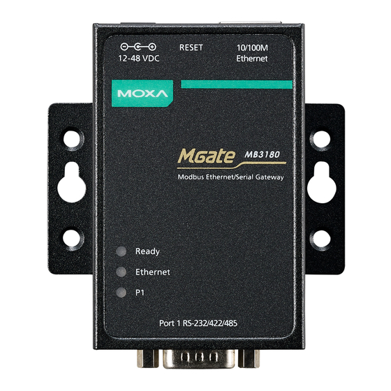
3. Hardware: MB3180 This chapter provides hardware information for the MGate MB3180. Panel Layout MGate MB3000 Modbus Gateway User Manual... -
Page 10: Led Indicators
LED Indicators Name Color Function Steady on: Power is on, and the unit is booting up. Blinking: Shows an IP conflict, or the DHCP or BOOTP server is not responding properly. Ready Steady on: Power is on, and the unit is functioning normally. Green Blinking: Unit is responding to software Locate function. -
Page 11: Jumpers
Jumpers To access these jumpers, loosen the screws on both sides of the device and open the cover. To set the pull high/low resistors to 150 KΩ, leave jumpers JP3 and JP4 open (not shorted). This is the default setting. To set the pull high/low resistors to 1 KΩ, short jumpers JP3 and JP4 with jumper caps. -
Page 12: Din Rail And Wall Mounting
DIN Rail and Wall Mounting Mounting on a DIN Rail: Attach the DIN-rail accessories and latch the unit onto the DIN Rail as shown. The DIN-rail kit is ordered separately. Mounting on the wall: Place two screws in the wall and slide the unit onto the screws as shown. -
Page 13: Hardware: Mb3280
4. Hardware: MB3280 This chapter provides hardware information for the MGate MB3280. Panel Layout MGate MB3000 Modbus Gateway User Manual... -
Page 14: Led Indicators
LED Indicators Name Color Function Steady on: Power is on, and the unit is booting up. Blinking: Shows an IP conflict, or the DHCP or BOOTP server is not responding properly. Ready Steady on: Power is on, and the unit is functioning normally. Green Blinking: Unit is responding to software Locate function. -
Page 15: Jumpers
Jumpers To access these switches, loosen the screws on both sides of the device and open the cover. To add a 120 Ω termination resistor, set switch 3 on the port’s assigned DIP switch to ON; set switch 3 to OFF (the default setting) to disable the termination resistor. To set the pull high/low resistors to 150 KΩ, set switches 1 and 2 on the port’s assigned DIP switch to OFF. -
Page 16: Din Rail And Wall Mounting
DIN Rail and Wall Mounting Mounting on a DIN Rail: Attach the DIN-rail accessories and latch the unit onto the DIN Rail as shown. The DIN-rail kit is ordered separately. Mounting on the wall: Place two screws in the wall and slide the unit onto the screws as shown. -
Page 17: Hardware: Mb3480
5. Hardware: MB3480 This chapter provides hardware information for the MGate MB3480. Panel Layout MGate MB3000 Modbus Gateway User Manual... -
Page 18: Led Indicators
LED Indicators Name Color Function Steady on: Power is on, and the unit is booting up. Blinking: Shows an IP conflict, or the DHCP or BOOTP server is not responding properly. Ready Steady on: Power is on, and the unit is functioning normally. Green Blinking: Unit is responding to software Locate function. -
Page 19: Jumpers
Jumpers HW version v1.3.3 or earlier HW version v1.4.0 or later To access these switches, loosen the screws on both sides of the device and open the cover. To add a 120 Ω termination resistor, set switch 3 on the port’s assigned DIP switch to ON; set switch 3 to OFF (the default setting) to disable the termination resistor. -
Page 20: Din Rail And Wall Mounting
DIN Rail and Wall Mounting Mounting on a DIN Rail: Attach the DIN-rail accessories and latch the unit onto the DIN Rail as shown. The DIN-rail kit is ordered separately. Mounting on the wall: You will first need to attach the mounting plates to the unit. Place four screws in the wall and slide the unit onto the screws as shown. -
Page 21: Hardware: Mb3170, Mb3170I
6. Hardware: MB3170, MB3170I This chapter provides hardware information for the MGate MB3170 and MB3170I. Panel Layout LED Indicators Name Color Function PWR1 Power is being supplied to the power input. PWR2 Power is being supplied to the power input. Steady on: Power is on, and the unit is booting up. -
Page 22: Dimensions
Dimensions MGate MB3000 Modbus Gateway User Manual... -
Page 23: Jumpers
Jumpers The DIP switches are beneath the DIP switch panel on the side of the unit. To add a 120 Ω termination resistor, set switch 3 to ON; set switch 3 to OFF (the default setting) to disable the termination resistor. To set the pull high/low resistors to 150 KΩ, set switches 1 and 2 to OFF. -
Page 24: Din Rail And Wall Mounting
DIN Rail and Wall Mounting There are two sliders on the back of the unit for DIN Rail and wall mounting. Mounting on a DIN Rail: Pull out the bottom slider, latch the unit onto the DIN Rail, and push the slider back in. -
Page 25: Specifications
Specifications Note The latest specifications for Moxa's products can be found at https://www.moxa.com. MGate MB3000 Modbus Gateway User Manual... -
Page 26: Hardware: Mb3270, Mb3270I
7. Hardware: MB3270, MB3270I This chapter provides hardware information for the MGate MB3270 and MB3270I. Panel Layout LED Indicators Name Color Function PWR1 Power is being supplied to the power input. PWR2 Power is being supplied to the power input. Steady on: Power is on, and the unit is booting up. -
Page 27: Dimensions
Dimensions MGate MB3000 Modbus Gateway User Manual... -
Page 28: Jumpers
Jumpers The DIP switches are beneath the DIP switch panel on the side of the unit. To add a 120 Ω termination resistor, set switch 3 on the port’s assigned DIP switch to ON; set switch 3 to OFF (the default setting) to disable the termination resistor. To set the pull high/low resistors to 150 KΩ, set switches 1 and 2 on the port’s assigned DIP switch to OFF. -
Page 29: Din Rail And Wall Mounting
DIN Rail and Wall Mounting There are two sliders on the back of the unit for DIN Rail and wall mounting. Mounting on a DIN-rail: Pull out the bottom slider, latch the unit onto the DIN Rail, and push the slider back in. -
Page 30: Pin Assignments
8. Pin Assignments DB9 (Male) The MGate MB3000 uses DB9 (male) serial ports to connect Modbus RTU or ASCII devices. Each port supports three serial interfaces: RS-232, RS-422, and RS-485 (both 2 and 4-wire). RS-422/ RS-232 RS-485 (2W) RS-485 (4W) TxD- –... -
Page 31: Typical Applications
9. Typical Applications Ethernet Clients/Masters With Multiple Serial Servers/Slaves Connect all Modbus devices over an Ethernet network Most modern PLCs and host computers support Modbus TCP over Ethernet. To access discrete Modbus RTU/ASCII devices for data collection and control, they can rely on the MGate MB3000 Modbus gateway. The MGate MB3000 supports Modbus TCP with up to 16 or 32 simultaneous connections. -
Page 32: Serial Clients/Masters With Multiple Ethernet Servers/Slaves
Serial Clients/Masters With Multiple Ethernet Servers/Slaves Link a serial client/master device with Ethernet server/slave devices Many Human-machine Interface (HMI) systems use a serial interface to connect to a discrete Data Control System (DCS). However, many DCSs are now Ethernet-based and operate as a Modbus TCP server/slave device. -
Page 33: Serial Client/Master With Serial Servers/Slaves Over Internet
Serial Client/Master With Serial Servers/Slaves over Internet Let Modbus serial devices communicate over the Internet Many Modbus devices communicate over RS-485, which limits the number of devices in a network to 32 and the transmission distance to 1.2 km. With the MGate MB3000 Modbus gateway, you can link all Modbus devices over an Ethernet network. Up to 32 Modbus gateways can be installed in a single control network, so each device can now be accessed from anywhere the TCP/IP network can reach. -
Page 34: Configuring The Modbus Gateway
Configuring the Modbus Gateway Installing the Software The following instructions explain how to install MGate Manager, a utility for configuring and monitoring MGate MB3000 units over the network. To install MGate Manager, please download it from Moxa’s website at http://www.moxa.com. Then run the following setup program to begin the installation process: moxa-mgate-manager-utility-[version].exe The filename of the latest version may have the following format:... - Page 35 When the Select Destination Location window appears, click Next to continue. You may change the destination directory by first clicking on Browse..When the Select Additional Tasks window appears, click Next to continue. You may select Create a desktop icon if you would like a shortcut to MGate Manager on your desktop. MGate MB3000 Modbus Gateway User Manual...
- Page 36 Click Install to copy the software files. A progress bar will appear. The procedure should take only a few seconds to complete. MGate MB3000 Modbus Gateway User Manual...
- Page 37 A message will show that MGate Manager is successfully installed. You may choose to run it immediately by selecting Launch MGate Manager. You may also open MGate Manager through Start > Programs > MGate Manager > MGate Manager, as shown below. MGate MB3000 Modbus Gateway User Manual...
-
Page 38: Starting Mgate Manager
Starting MGate Manager MGate Manager is a Windows-based utility that is used to configure the MGate MB3000. Before running MGate Manager, make sure that your PC and the MGate MB3000 are connected to the same network. Alternatively, the MGate MB3000 may be connected directly to the PC for configuration. Please refer to Chapter 2 for more details. -
Page 39: Connecting To The Unit
When you click OK, MGate Manager will immediately switch to your chosen language. ATTENTION Use Default Language before contacting Moxa Technical Support. With support for multiple languages, MGate Manager is more user-friendly and accessible. However, if you need help from Moxa Technical Support, please change the language to Default Language. This will prevent any misunderstandings or confusion about MGate Manager menu items and commands as our engineers assist you. -
Page 40: Broadcast Search
Broadcast Search Click Search and a new Search window will pop up. Select Broadcast Search and click OK to search the LAN for all MGate MB3000 units. MGate MB3000 Modbus Gateway User Manual... -
Page 41: Specify Ip Address
When the search is complete, every MGate MB3000 that is found on the LAN will appear in the window with MAC address and IP address. Select the one that you wish to configure. Specify IP Address Click Specify IP Search Address if you know the IP address of the unit and wish to connect to it directly. Enter the unit’s IP address and click OK. - Page 42 If the search is successful, the model items will be listed in MGate Manager. Configuration can be done in two ways. The first way is to left-click the item to start MGate Manager configuration. The second way is to right-click the item to begin the web console configuration. You must provide the correct password to log in to the web console.
-
Page 43: Changing The Configuration
Changing the Configuration Once your unit is displayed in MGate Manager, click on it to select it. The Configuration button will become available. Click Configuration to open the configuration window. Password Protection For security reasons, account and password protection is enabled by default, so you must provide the correct password to unlock the device before configuring the device. -
Page 44: Basic Settings
Such as “Cabinet A001.” Time Settings The MGate MB3000 Series has a built-in real-time clock for time-calibration functions. Functions, such as the log function, can add real-time information to the message. You can do time calibration either followed by local time or time server. Please note that this feature is not supported by the MB3180 gateway. -
Page 45: Network Settings
Network Settings The Network tab is where the unit’s network settings are configured. You can modify the Name, Network Configuration, IP Address, Netmask, Default Gateway, and DNS. You can also change it on the web console. Click Basic Settings > Network. You can change the Name, IP Configuration, IP Address, Netmask, Default Gateway, and DNS. -
Page 46: Serial Settings
DNS Server Parameter Value Notes 0.0.0.0 DNS Server 1 This is the IP address of the primary domain name server. (or other 32-bit number) 0.0.0.0 DNS Server 2 This is the IP address of the secondary domain name server. (or other 32-bit number) Serial Settings The MGate MB 3000 Series serial interface supports RS-232, 2-wire RS-485, 4-wire RS-485, and RS-422 interfaces. -
Page 47: Protocol Settings
Protocol Settings Mode The MGate gateway supports Modbus RTU/ASCII and Modbus TCP protocols. The operation mode determines whether the device(s) that are connected to the serial port will operate as a client/master or a server/slave and whether the Modbus RTU or Modbus ASCII protocol will be used. Four operation modes are available: Mode Description... - Page 48 Modbus You can make certain adjustments in the Modbus tab to fine-tune the communication between different Modbus networks. You can configure Initial Delay, Modbus TCP Exception, Slave Channel, and Response Time-out. Parameter Value Initial Delay Numeric Modbus TCP Exception Enable or Disable Slave Channel Port 1, Port 2, TCP/ProCOM Listen Port...
- Page 49 Modbus TCP Port Allows you to change the Modbus TCP listen port from the default value (502). Slave Channel and Response Time-out According to the Modbus standard, the time that it takes for a server/slave device to respond to a request is defined by the device manufacturer (please refer to Appendix A for details).
- Page 50 Modbus Routing The Modbus Routing tab is where the Modbus slave IDs are managed. The definitions on this tab determine how Modbus requests will be routed to the serial ports by the gateway. Port Routing Table The MGate MB3000 gateways support two kinds of port routing mechanism: by IP address and by TCP port.
- Page 51 For example, you could assign TCP ports 2001 to 2004 to serial ports 1 to 4, respectively. When the gateway receives a Modbus request designated for TCP port 2001, it will forward the Modbus request to serial port 1 directly. Similarly, if it receives a Modbus request designated for TCP port 2004, it will forward the Modbus request to the serial port 4 directly.
- Page 52 Users have to set their own customized routing. Select the one you want to set and click Add/Remove/ Modify buttons to change the existing routing. Set each port one by one. Auto Device Routing The Moxa Modbus gateways provide an auto routing mechanism that eliminates the burdensome task of setting the slave ID table manually.
- Page 53 If a conflict exists, the table will show the error in red. For example, two Modbus devices with the same slave ID are connected in serial port 1 and port 2. On the other hand, if you have manually set the routing table already, and you would like to enable the auto-routing mechanism for the newly added devices, click No to keep the existing routing table.
- Page 54 Select the second channel and click Modify. Since the virtual ID recognized by the Modbus client/master is 2, and the real slave ID of the device B is ID 1, the offset should be set as -1. The routing table will show up as follows: Now, the Modbus client/master can send a request with slave ID 1 to Modbus device A connected to serial port 1 as well as send a request with slave ID 2 to the Modbus device B connected in serial port 2.
- Page 55 Priority Control The Priority Control tab is where emergency requests are enabled and configured. This is available for advanced models only (MB3170, MB3170I, MB3270 and MB3270I). Priority control is designed for requests that are sent to Modbus RTU/ASCII servers/slaves. Since Modbus RTU/ASCII servers/slaves cannot handle multiple requests, the Modbus gateway must send each request individually and wait for the response before sending the next request.
-
Page 56: System Settings
System Settings Accessible IP The MGate MB3000 uses an IP address-based filtering method to control access to itself. The Accessible IP List function allows you to add or block remote host IP addresses to prevent unauthorized access. Access to the MGate MB3000 is controlled by IP address. That is, if a host’s IP address is in the accessible IP table, then the host will be allowed to access the MGate MB3000. - Page 57 System Log These settings enable the MGate firmware to record important events for future verification. The recorded information can only be displayed in the web console. Please note that this feature is not supported on MB3180 gateway. The information that can be recorded includes the following events: Event Group Description System...
- Page 58 Auto Warning Settings Auto Warning is triggered by different events. When a checked trigger condition occurs, the MGate can send e-mail alters, SNMP Trap messages, or open/close the circuit of the relay output and trigger the Fault LED to blink. To enable an e-mail alert, configure the e-mail address on the E-mail Alert page. Likewise, to enable SNMP Trap alerts, configure the SNMP trap server on the SNMP Trap page.
- Page 59 This is a text password mechanism that is used to weakly authenticate changes Write community string to agents of managed network devices. SNMP agent version The MGate MB3000 Series supports SNMP V1, V2c, and V3. MGate MB3000 Modbus Gateway User Manual...
- Page 60 Read-only and Read/write access control While selecting SNMP agent version V3, it is needed to configure read-only and read/write access control parameters. The following fields allow you to define usernames, passwords, and authentication parameters for two levels of access: read-only and read/write. The name of the field will indicate which level of access it refers to.
- Page 61 Notification Message The login message and login authentication failure message can be configured. Account Management A group of accessible accounts with two different user levels can be managed. Parameters Value Description Account Name Users can set up the account name for login purpose. Users can change the password for different accounts.
- Page 62 Login Password Policy Considering security level, the login password policy and failure lockout can be configured. Account Password Policy Value Description Minimum length 4 to 16 Enable password complexity strength Select how the MGate checks the password strength check 90 to 180 Password lifetime Set the password lifetime period days...
-
Page 63: Serial Redirector Settings
NOTE The maximum key length of the MGate devices supports 2,048 bits. Some well-known third-party CA (Certificate Authority) companies are listed below for your reference: (https://en.wikipedia.org/wiki/Certificate_authority): IdenTrust (https://www.identrust.com/) DigiCert (https://www.digicert.com/) Comodo Cybersecurity (https://www.comodo.com/) GoDaddy (https://www.godaddy.com/) Verisign (https://www.verisign.com/) Serial Redirector Settings An advanced multiport MGate model (MB3270/MB3270I) supports the serial redirector function, which integrates Modbus RTU/ASCII and Modbus TCP devices simultaneously. - Page 64 Configuring Serial Redirector Serial Redirector can be set up by Protocol Settings—Mode and Modbus Routing. For detailed information, refer to the following scenario and steps. Scenario 1: Adding Modbus TCP Client/Master (SCADA) to an existing Modbus serial system A Modbus RTU client/master, such as HMI, controls the Modbus RTU server/slave in the original system. Now you want to add a Modbus TCP client/master such as SCADA into the system and keep the serial Modbus RTU system.
- Page 65 Scenario 2: Adding Modbus TCP Server/Slave to an existing Modbus serial system There is a Modbus RTU client/master such as HMI that controls the Modbus RTU server/slave in the original system. Now you want to add the Modbus TCP server/slave such as PLC into the system and keep the serial Modbus RTU system.
-
Page 66: Verifying The Location Of The Unit
Verifying the Location of the Unit If you are managing multiple MGate units, you may wonder if you are configuring the correct unit in MGate Manager. You can select a unit in MGate Manager and click Locate to make the unit’s Ready LED blink for a few seconds. - Page 67 Open Traffic Monitor Window Select the unit that you wish to monitor and click Monitor to open the Traffic Monitor window. In the Traffic Monitor window, click Start to begin live monitoring of the data passing through the selected MGate MB3000 unit. MGate MB3000 Modbus Gateway User Manual...
- Page 68 To stop capturing the log, press the Stop button. MGate MB3000 Modbus Gateway User Manual...
- Page 69 Filter Traffic Information The traffic monitor window displays all events by default. MGate Manager also allows the data to be filtered so only the relevant information is displayed. The filter is selected, using the radio buttons, and customized, using the Filter info field, as follows: Filter Customization Description...
- Page 70 After clicking Save, a window pops up where you can select the location to save the log file. To save the file to .csv format, click Browse and select the drop-down menu to choose .csv format. MGate MB3000 Modbus Gateway User Manual...
-
Page 71: Procom Mapping
ProCOM Mapping If your system uses remote PCs that only support COM port behavior to control remote Modbus devices, then ProCOM is the best solution for your system. Before using ProCOM, your PC needs to create virtual COM ports that connect to a specific ProCOM over an Ethernet network. By using ProCOM, the MGate MB3x70 will treat your PC’s COM port as if it were an additional serial port on the MGate MB3x70. - Page 72 This way, when you send a Modbus request to ProCOM, the driver will forward your request to the MGate MB3x70 and the MGate MB3x70 will forward the request to the target Modbus device using the preset Modbus device mode and Slave ID. For example, the Modbus request from ProCOM can be redirected to a Modbus RTU/ASCII device that is behind the MGate MB3x70’s serial interface or to a Modbus TCP device through the MGate MB3x70’s Ethernet port.
- Page 73 Once finishing configuring the COM port, click OK and check if the COM port is changed successfully. Offline Open This function enables users to open ProCOM port(s) before the device is connected. Here, the data transmitted to ProCOM port(s) will be stored temporarily and will be sent out once the ProCOM port(s) are ready for access.
-
Page 74: Upgrading Firmware
The Offline Open function is changed successfully from the mapping table. Upgrading Firmware The updated MGate MB3000 Series firmware is at http://www.moxa.com. After you have downloaded the new firmware onto your PC, you can use MGate Manager to write it onto your MGate MB3000 gateway. - Page 75 The dialog boxes will guide you through the process. You will need to browse your PC for the firmware file. Make sure that it matches your model. As the firmware is written to the unit, progress is displayed in the window. ATTENTION DO NOT turn off the MGate’s power before the firmware upgrade process is completed.
-
Page 76: Load Default
Load Default To clear all the settings on the unit, use the Load Default button to reset the unit to its initial factory default values. Click Load Default and review the confirmation message. If you are sure you would like to reset the configuration to factory defaults, click the OK button. -
Page 77: Export/Import
Moxa’s Technical Service Team when maintenance visits are requested. Export Function The export function saves all the configuration settings and parameters of the MGate MB3000 Series in a *.cfg file. To begin, click the Export button. Enter a file name and use the Browse button to save the file to a specific path. Then, click the OK button. - Page 78 Import Function Once the file is saved, it can be imported into your target unit to duplicate the same settings. Select the target unit first and click the Import button to import. Select the file you want to import, and then click the OK button Wait for the MGate Manager to finish configuring the target device.
-
Page 79: Network Management Tool (Mxstudio)
Network Management Tool (MXstudio) For the software and related detailed information regarding MXview and MXconfig, as well as the supported product firmware versions, please refer to the Moxa website at https://www.moxa.com/en/products/industrial-network-infrastructure/network-management-software. When you discover a Moxa product that has not been integrated into MXview or MXconfig, you may not be able to retrieve the product information from MXview or MXconfig. -
Page 80: Case Studies
Case Studies Introduction There are many reasons a Modbus gateway might be used to integrate Modbus networks. However, every situation has its own requirements and difficulties. Users may wonder how the gateway can help, or even if the gateway is suitable for the system. This chapter presents some case studies to guide you. -
Page 81: Replace Serial Clients/Masters With Ethernet Client(S)/Master(S), Slave Ids Are Fixed
Replace Serial Clients/Masters With Ethernet Client(s)/Master(s), Slave IDs Are Fixed Some legacy Modbus server/slave devices have fixed IDs that cannot be changed. In order to integrate the devices into a Modbus TCP network, a multiport MGate model (MB3280, MB3270, or MB3480) can be used to assign virtual slave IDs. -
Page 82: Serial Redirector
Serial Redirector An advanced multiport MGate model (MB3270/MB3270I) supports the serial redirector function, which integrates Modbus RTU/ASCII and Modbus TCP devices simultaneously. Many serial control systems in the field and local control devices, such as HMI, are connected to serial field devices. Using Ethernet-based equipment for remote access and monitoring has become a trend. -
Page 83: Modbus Overview
A. Modbus Overview Introduction Modbus is one of the most popular automation protocols in the world. It supports both serial and Ethernet devices. Many industrial devices, such as PLCs, DCSs, HMIs, instruments, meters, motors, and drivers, use Modbus as their communication standard. Devices Are Either Clients/Masters or Servers/Slaves All Modbus devices are classified as either a client/master or a server/slave. -
Page 84: Requests Need A Time Limit
Exception The client/master sends a request to the server/slave. The server/slave may not support the command, or an error is detected, so it sends an exception to the client/master. Broadcast The client/master sends a broadcast command, such as a reset command. Every server/slave on the network complies with the command, and no response is sent to the client/master. -
Page 85: Modbus Ethernet Vs. Modbus Serial
Modbus Ethernet vs. Modbus Serial Although Modbus is intended as an application-layer messaging protocol, the data format and communication rules for Ethernet-based Modbus TCP differ from serial-based Modbus ASCII and RTU. The major difference between the Ethernet and serial Modbus protocols is the behavior of the communication model. -
Page 86: Snmp Agents With Mib Ii And Rs-232-Like Groups
B. SNMP Agents With MIB II and RS-232- Like Groups The MGate MB3000 Series has built-in Simple Network Management Protocol (SNMP) agent software that supports SNMP Trap, RFC1317 and RS-232-like groups, and RFC 1213 MIB-II. RFC1213 MIB-II Supported SNMP Variables... -
Page 87: Rfc1317 Rs-232-Like Groups
Address TCP MIB UDP MIB SNMP MIB Translation MIB atIfIndex tcpRtoAlgorithm udpInDatagrams snmpInPkts atPhysAddress tcpRtoMin udpNoPorts snmpOutPkts atNetAddress tcpRtoMax udpInErrors snmpInBadVersions tcpMaxConn udpOutDatagrams snmpInBadCommunityNames tcpActiveOpens udpLocalAddress snmpInBadCommunityUses tcpPassiveOpens udpLocalPort snmpInASNParseErrs tcpAttemptFails snmpInTooBigs tcpEstabResets snmpInNoSuchNames tcpCurrEstab snmpInBadValues tcpInSegs snmpInReadOnlys tcpOutSegs snmpInGenErrs tcpRetransSegs snmpInTotalReqVars tcpConnState...
Need help?
Do you have a question about the MGate MB3000 Series and is the answer not in the manual?
Questions and answers