Vivax Metrotech vLoc3 Series User Manual
Hide thumbs
Also See for vLoc3 Series:
- User handbook manual (68 pages) ,
- User manual (16 pages) ,
- Quick manual (4 pages)
Table of Contents
Advertisement
Quick Links
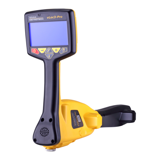
vLoc3 Series A-frame User Guide V1.1
vLoc3 Series A-frame Overview
1
2
3
Using the vLoc3 Series A-frame Fault Finding Accessory
The vLoc3 series A-frame accessory is used to detect ground faults on pipes and cables. In the
case of pipes, the faults consist of coating defects. In the case of cables, faults are usually caused
by insulation damage allowing the metallic sheath (or internal conductor) to become in contact
with the ground.
It is intended to be used with the vLoc3 range of receivers and will require a fault find frequency
applied to the faulty conductor from a Vivax-Metrotech compatible transmitter.
P/N:4.04.000110
1
Accessory A-frame receiver
2
Rubber spike cover
3
Interconnect cable
5
4
Quick guide
5
A-frame soft carry bag
4
™
Page 1
Advertisement
Table of Contents

Subscribe to Our Youtube Channel
Related Manuals for Vivax Metrotech vLoc3 Series


Summary of Contents for Vivax Metrotech vLoc3 Series
- Page 1 Using the vLoc3 Series A-frame Fault Finding Accessory The vLoc3 series A-frame accessory is used to detect ground faults on pipes and cables. In the case of pipes, the faults consist of coating defects. In the case of cables, faults are usually caused by insulation damage allowing the metallic sheath (or internal conductor) to become in contact with the ground.
- Page 2 Note Fault finding requires a non standard frequency. Historically there have been many versions of fault finding frequencies. Some of these are listed below: - 3/6Hz Fault find (Used to detect faults on pipelines) - Signal Select Fault find (Good for fault finding on short runs such as power networks) - SD Fault find (General purpose fault finding) - 8kFF (General purpose fault find with good results on short and long runs and has good sensitivity) For the purposes of this manual 8kFF is concentrated on as it gives the best overall performance.
- Page 3 26 dB 8KFF The above image is for reference only and may differ from actual image Remove the rubber spike covers from the A-frame. Walk along the route of the line placing the spikes of the A-frame in the ground (with the green leg pointing away from the transmitter connection point) every two or three paces.
- Page 4 Eventually the A-frame will detect the fault signal and the “Fault Find” arrow will point forward. Continue moving forward, it may be worth reducing the distance between measurements points as the fault is neared. The dB reading will increase as the fault is neared. Maximum reading will be just before and just after the fault.
Need help?
Do you have a question about the vLoc3 Series and is the answer not in the manual?
Questions and answers