Vivax Metrotech vLoc3 RTK-Pro User Handbook Manual
Hide thumbs
Also See for vLoc3 RTK-Pro:
- User handbook manual (76 pages) ,
- Quick setup manual (28 pages) ,
- Quick setup manual (36 pages)
Table of Contents
Advertisement
Advertisement
Table of Contents

Related Manuals for Vivax Metrotech vLoc3 RTK-Pro


Summary of Contents for Vivax Metrotech vLoc3 RTK-Pro
- Page 1 RTK-Pro User Handbook (English Edition) Version 1.0 P/N: 4.04.000170...
- Page 3 General Safety & Care Information 5. General Rules regarding Disposal of Batteries Who Can Use This Equipment • Never disassemble a battery, or battery pack. • This equipment must only be used by people suitably trained in the use of pipe and •...
-
Page 5: Table Of Contents
2.6.1 Signal Overload................................9 2.6.2 Shallow Cable................................9 2.6.3 Swing Alert................................9 2.6.4 Overhead cable................................9 Setting up the vLoc3 RTK-Pro mapping functions......................9 vLoc3 RTK-Pro Receiver Locate Screen Shots.........................16 Classic Locating Modes (Response)..........................18 2.9.1 Peak Response Mode............................18 2.9.2 Broad Peak Mode..............................18 2.9.3 Null Mode................................19 2.9.4... - Page 6 Passive Locating.................................24 3.2.1 Detecting Power Signals............................25 3.2.2 Detecting Radio Signals............................26 Active Locating:- Applying the Transmitter........................26 3.3.1 Direct Connection..............................26 3.3.2 Signal Clamp (for frequencies above 8kHz)......................28 3.3.3 Induction (for frequencies above 8kHz)........................29 Locating Active Signals..............................30 Searching (sweeping) an Area in the Peak Mode......................31 Searching (sweeping) an Area in the Omni Peak Mode....................31 Tracing a Buried Line................................31 Depth &...
- Page 7 Using the Accessories...................................58 Using the LPC Separation Filter............................58 Using the Analogue A-frame Fault Finding Accessory.....................58 Using the vLoc3 RTK-Pro Remote Antenna........................61 Using the SD Signal with the Remote Antenna to help trace a particular cable...............63 Accessories & Options..................................66 A-frame....................................66 Clamps....................................66 vLoc3-MLA (Marker Locator Adapter)..........................66...
-
Page 9: Service & Support
Service & Support Service & Support 1. Service & Support Serial Number and Software Revision Number Always quote your receiver and transmitter model number, serial number and software revision number when requesting product support. They can be found as follows: (for reference only). Model &... -
Page 10: Distributors And Service Centers Closest To You
Service & Support Distributors and Service Centers Closest to You: Worldwide Sales Offices and Service Centers World Headquarters, United States of America Central/South America and the Caribbean Vivax-Metrotech Corporation Ventas para América Latina 3251 Olcott Street, 3251 Olcott Street, Santa Clara, CA 95054, USA Santa Clara, CA 95054, USA Website : www.vivax-metrotech.com T/Free... -
Page 11: Vloc3 Rtk-Pro Receiver
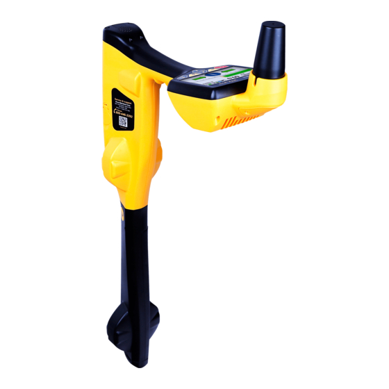
RTK-Pro Receiver vLoc3 RTK-Pro Receiver vLoc3 RTK-Pro Receiver Overview The vLoc3 RTK-Pro is a Precision Location System designed to meet the needs of utility companies and their contractors. The following describes the features and use of the receiver. vLoc3 RTK-Pro receiver... -
Page 12: Charging The Receiver Batteries
RTK-Pro Receiver Charging the Receiver Batteries The vLoc3 RTK-Pro can be used with either alkaline batteries or an interchangeable rechargeable battery pack. The central illuminated section within the battery icon indicates the amount of charge remaining. ● Blue center indicates alkaline batteries ●... -
Page 13: Vloc3 Rtk-Pro Receiver Keypad
User Menu The vLoc3 RTK-Pro has several features that can be switched on and off. These features are accessed through the user menu. Switch on the unit by pressing and holding the On/Off key until the start-up screen appears. The start-up screen can be configured to the user’s preference and is described later in the manual. -
Page 14: About
RTK-Pro Receiver Where the icon is not shown, the enter button is used to scroll through the options of that feature. Use the “+” and “- “buttons to scroll up and down through the menu. The features are described below: 2.4.1... -
Page 15: Locate Perspective
2.4.13 GPS Source Press the “Enter” key to select either Internal or Bluetooth. For the vLoc3 RTK-Pro, this is typically set to internal. 2.4.14 Satellite Information Press the enter button to reveal all satellite information 2.4.15 Transmitter Link... -
Page 16: Cloud
Metrotech Corporation or one of its authorized service centers for repair. Self-Test The vLoc3 RTK-Pro has a self-test feature. The test confirms that the equipment is fit for use and calibration has not drifted from its expected settings. To undertake the test, first find an area free from excessive interference such as overhead fluorescent lighting, large transformers etc. -
Page 17: Warnings
Introduction This section describes the set-up and operation of the vLoc3 RTK-Pro in terms of the GNSS mapping capabilities. The equipment is designed to provide cm accuracy. However, GNSS on its own is not capable of providing the cm accuracy that is required for many survey applications. - Page 18 RTK-Pro Receiver Satellite Satellite Internet (Cloud) Satellite Satellite Cellular Tower Trip caster vLoc3 RTK-Pro Base 1 Base 2 Base 3 This set-up procedure assumes the operator has a suitable data-enabled SIM card registered with a cellular network provider and that the operator has registered with an RTK provider. It is also assumed that the operator has the latest version of MyLocator3 installed on a computer.
- Page 19 RTK-Pro Receiver Setting up RTK connections using MyLocator3 Connect the locator to the computer running the MyLocator3 app. The app is available at www.vivax-metrotech.com and is free of charge. Launch MyLocator3 app and a screen similar to the below will appear. Note the purple Update Now box will appear when an update is available.
- Page 20 RTK-Pro Receiver It should now be possible to start using the locator, but first, a few settings in the locator need to be set. 1) Switch on the units and enter the user settings by using a long press of the info key. Scroll to the “About” option and press the return key.
- Page 21 RTK-Pro Receiver Scroll to the source you wish to use and press the enter key to select. “RTCM status” will show “Waiting,” then “Connecting,” then “Requesting RTCM” then “Receiving RTCM” as the vLoc3-RTK receives RTCM from the NTRIP caster. In this case the “RTK source”...
- Page 22 RTK-Pro Receiver This screen becomes available from the main menu once the cellular module has been found. Initially it will show “Cloud status” “No Network”. Once a cellular network data connection has been made it will show “Cloud status” “Waiting”.
- Page 23 If a new survey is started and new logs are taken, a new survey ID will be requested before the logs in the new survey are sent to the Cloud. Using the vLoc3 RTK-Pro A note on battery consumption The vLoc3-RTK has considerably more electrical circuitry than a standard vLoc3. Therefore, the power drain from the battery is considerably more.
-
Page 24: Vloc3 Rtk-Pro Receiver Locate Screen Shots
The user interface of the vLoc3 RTK-Pro is under continual development. The screenshots described may differ slightly from current screens. The vLoc3 RTK-Pro gives the user a choice of different locate screens. The choice of screen depends on application and user preference. - Page 25 RTK-Pro Receiver The Classic Screen has all the functions normally seen on a classic cable locator. The main functions being: 50mA 69.9 58dB 2’7” 32.8kHz Percentage signal strength (mirrors the bar graph setting) Peak level indicator Gain setting Bar graph signal strength indicator (changes colour depending on distortion level) Green: - low distortion.
-
Page 26: Classic Locating Modes (Response)
Classic Locating Modes (Response) The vLoc3 RTK-Pro receiver has an array of six antennas, and these can be toggled through different configurations (modes) to provide different responses to the signals radiating from buried utilities. The modes are: 2.9.1... -
Page 27: Null Mode
RTK-Pro Receiver 2.9.3 Null Mode This uses vertical antennas, and provides a minimum or “Null” response over the center of the buried line. The compass (line direction indicator) aligns itself parallel to the direction of the cable (available in Active modes). -
Page 28: Information Pushbutton (Depth & Current)
Alternative Locate Screens As previously mentioned, the vLoc3 RTK-Pro has a number of alternative screens. The following section describes the operation of these screens. It is left to the user to decide which is the best screen for a particular application. - Page 29 RTK-Pro Receiver Sonde Specific mode for detecting and locating sonde transmitters. Vector Shows a cross-section of the ground and line position relative to the locator. configuration Plan view Gives a plan view as if looking into the ground. Shows a graphical representation of the peak and null field shape over a line (Active Trans.
- Page 30 RTK-Pro Receiver The color of the confidence circle also changes depending on the degree of confidence: Green: - low distortion/high confidence. Blue: - Minor distortion/medium confidence, proceed with care. Red: - Excessive distortion/low confidence, treat all data and measurements with caution.
- Page 31 RTK-Pro Receiver “Tram” lines either side of the line indicate an area of confidence. The closer the tram lines are together, the greater the confidence. In addition to the tram lines, the color of the target line also changes depending on the degree of confidence: Green: - low distortion/high confidence.
-
Page 32: Using The Vloc3 Rtk-Pro
Using the vLoc3 RTK-Pro Using the vLoc3 RTK-Pro Using the Receiver Line Locating - Using the “Classic” Screen. 50mA 69.9 58dB 2’7” 32.8kHz Passive Locating NOTE The compass indicator is not active during a passive location. Passive locating refers to the process of detecting signals that “naturally” occur on pipes and cables. These tend to fall into two categories, radio signals, and power signals. -
Page 33: Detecting Power Signals
Keeping the vLoc3 RTK-Pro vertical, walk across the area to be checked, keeping the orientation so that the blade is in line with the direction of walking (See diagram above). If using the Onmi Peak mode, the orientation of the locator is not important. -
Page 34: Detecting Radio Signals
Using the vLoc3 RTK-Pro Rotate the vLoc3 RTK-Pro on its axis to obtain the maximum signal. The vLoc3 RTK-Pro is now directly over the line and with the blade across the line. (If using the Omni-Peak mode there will be no change so switch to Peak mode if the direction is required). - Page 35 Using the vLoc3 RTK-Pro WARNING Only authorized personnel should make connections to cables. To make a direct connection, insert the direct connection connector to the transmitter. Insert the ground stake into the ground a few meters perpendicular to the line. Connect the black lead to the ground stake. Now take the red lead and connect to the target line.
-
Page 36: Signal Clamp (For Frequencies Above 8Khz)
Using the vLoc3 RTK-Pro 3.3.2 Signal Clamp (for frequencies above 8kHz) In many situations, it is not possible to gain access to a cable to make an electrical contact. Or if there is, it is not safe to do so. -
Page 37: Induction (For Frequencies Above 8Khz)
With no direct connection lead or signal clamp connected, the transmitter will automatically start to radiate a signal around the transmitter. These signals will penetrate the ground and couple onto buried lines. The signal will then travel along the line, which can be detected with the vLoc3 RTK-Pro locator. Applying an induction signal to a line. -
Page 38: Locating Active Signals
It may be necessary to reduce the sensitivity to keep the bar graph on the scale. This is normal and should be expected. Try to keep the vLoc3 RTK-Pro vertical and avoid swinging it as this may create false readings. -
Page 39: Searching (Sweeping) An Area In The Peak Mode
Using the vLoc3 RTK-Pro If the signal is not distorted, the position of the maximum signal will coincide with the position, as indicated by the arrows. If these two positions do not agree, it may be because there is signal distortion. Treat the results with caution. -
Page 40: Depth & Current Measurement
If the depth measurement feature is activated, it is possible to take depth measurement estimations. To take a depth measurement, first, pinpoint the position of the line as above. Place the tip of the vLoc3 RTK-Pro on the ground making sure it is vertical and across the line i.e. -
Page 41: Distorted Fields
As seen previously, the vLoc3 RTK-Pro has the ability to detect the presence of possible distortion, i.e. the Vector screen has a circle drawn around the target line which increases in size in the presence of possible distortion, and the Plan view screen has “Tram”... -
Page 42: Sonde Location Mode
– a small peak with two “Nulls” between the peaks. The sonde is located under the center of the “large peak” The vLoc3 RTK-Pro detects the presence of the two “Null” signals and also the position of the main “Large Peak”. It uses this information to provide a reliable and efficient method of sonde location. - Page 43 Using the vLoc3 RTK-Pro 65.3 25dB 640Hz If the bar graph is not steady it will most likely be because the sonde is not within range. In this case hold the locator at approximately 45 degrees to the ground and rotate the locator around a full 360 degrees around you.
-
Page 44: Data Logging
4. Data Logging The vLoc3 RTK-Pro has an internal memory that can be used to store locator data. (Or if activated, can be sent to the “cloud”) Available storage size is four Gigabyte which relates to many thousands of records. -
Page 45: Pairing With External Devices Such As A Datalogger Or A Mobile Phone
● Switch on the external device. ● Switch on the vLoc3 RTK-Pro and enter the User setup menu by a long press on the “i” button. ● Use the “+” and “-” keys to scroll down to the option “Bluetooth Pairing”. -
Page 46: Transferring Data From The Locator To A Computer
Bluetooth devices). Once paired with an external device, the vLoc3 RTK-Pro will await valid GPS data from the external device. The GPS icon will turn green when a valid GPS signal is detected. This can take from a few seconds to a few minutes depending on the device and whether it is doing a “cold”... -
Page 47: Application Update
Data Logging Clicking on the Clock symbol sets the locator time to UTC time. To check local and UTC time, hover over the icon and the times will be displayed to the right, flashing alternately. MyLocator3 can also be viewed in a number of language options. Click on the pull-down menu to select the desired option. Checking the “Auto Load Config”... -
Page 48: Locator Firmware Update
Toolbar The vLoc3 RTK-Pro locator can be configured so that features can be switched on or off. This enables the user to tailor the instrument to meet the needs of their application while keeping the user interface uncluttered. The toolbar at the top of the screen enables the user to create configurations. -
Page 49: Feature Tabs
Data Logging 4.2.4 Feature tabs The feature tabs run along the side of the display. Options such as radio mode frequency band Menu settings Frequency selections Splash screen Cloud (internet) settings Datalog Check for updates 4.2.5 Data Logging Clicking on the Data Logging tab will display information about the state of the attached locator’s data log contents. The data log contents can be stepped-though by using the controls on the right-hand side. -
Page 50: Splash Screen
Data Logging Before exporting the data, use the “Log Type” dropdown tab to select the type of data required. Options are: 4.2.6 Splash Screen On this page an image can be loaded which can be used as a splash screen by the locator when it is switched on. The locator has an LCD screen with a resolution of 480 by 272 pixels. -
Page 51: Frequencies Page
Data Logging 4.2.7 Frequencies Page The “Frequencies” page will allow the user to refine which frequency modes are available when the locator F-key is pressed and which frequencies appear on the locator menu. 4.2.8 Menu Settings The “Menu Settings” page allows the user control over which menu items appear on the locator and also the initial setting of the menu item when the locator is first used after configuration. -
Page 52: Cloud/Internet/Rtk Settings
Data Logging 4.2.9 Cloud/Internet/RTK settings Click on the Cloud/Internet icon which allows you to set the cloud settings. A Screen similar to the one below will be shown: “Network” “apn:” should be adjusted to the Access Point Name for your chosen Mobile network – be sure not to add any spaces before or after the APN. -
Page 53: Advanced Features
Data Logging 4.2.10 Advanced Features The Advanced Features are available to those users in possession of a USB security dongle. If a dongle is attached to the PC then its level will be displayed on the MyLocator3 status bar. 4.2.10.1 Supervisor Lockouts This feature is available to anyone with a dongle (contact Vivax-Metrotech for the purchase of a dongle).When a dongle is connected to your computer via a standard USB socket, the icons for the “Splash Screen”... -
Page 54: Loc3 Series Transmitters
Loc3 Series Transmitters Loc3 Series Transmitters This section of the manual covers both the 5-watt and 10-watt Loc3 transmitters. Loc3 Series Transmitter Overview The Loc3 series transmitters are rugged portable transmitters powered by alkaline “D” cells or Li-ion rechargeable batteries. The following describes the features and uses of the transmitter. -
Page 55: Pushbuttons
Loc3 Series Transmitters 5.1.2 Pushbuttons On/Off control Frequency select Information (Volume, Volts, Ohms, Multi-frequencies LCD contrast, Bluetooth menu, Frequency menu) Output decrease/Navigate through the menu Output increase/Navigate through the menu 5.1.3 Information Pushbutton Frequency Menu Frequency Menu Bluetooth Menu Bluetooth Menu LCD Contrast LCD Contrast Multi Frequency... -
Page 56: Transmitter Batteries
Loc3 Series Transmitters Transmitter Batteries In most markets the transmitter is shipped with alkaline batteries unless rechargeable batteries are specified. The battery status is displayed on the left side of the display. The 5-watt transmitter uses 8 x D cell alkaline batteries while the 10-watt uses 12. The letters “LP”... -
Page 57: Re-Fitting The Battery Tray
Loc3 Series Transmitters WARNING Alkaline Batteries – insert alkaline batteries as shown: 5-Watt = 8 x D Cells 10-watt = 12 x D Cells 5.2.3 Re-fitting the Battery Tray To close the battery tray – slide the transmitter (TX) onto the tray, it will locate itself in the correct position, then close the catches. -
Page 58: Transmitting Modes
Loc3 Series Transmitters Transmitting Modes The transmitter has three transmitting modes, which are selected automatically. 5.3.1 Induction Mode This uses an internal antenna to induce a locating frequency onto the target pipe or cable (line). “Induction” mode is automatically selected if no connection accessories are plugged into the “output socket”. An icon indicating “Induction” mode shows on the display. -
Page 59: Clamp Mode
Loc3 Series Transmitters The positioning of the ground connection can also influence the degree of coupling experienced. Ground connections generally should not be made to other pipes or cables, or above ground metallic structures such as wire fences. In general the lower the frequency is, the further the signal will travel, and the less signal-coupling will occur. -
Page 60: Most Used Frequencies (Frequency Selection) Feature
Loc3 Series Transmitters 200 kHz direct connection 1 watt (depending on region) Direct connection: 256Hz, 491Hz, 982Hz, etc Direct and clamp connection: 8.19 kHz, 8.44 kHz, 9.5 kHz, 9.82 kHz, 32.8 kHz, 38 kHz Some other frequencies with 1W output: 89 kHz, 131 kHz, 200 kHz 1 watt (depending on region) Clamp connection: any frequency from 8 kHz up to the highest allowed frequency (depending on region). - Page 61 Loc3 Series Transmitters To enter the “Frequency Menu” proceeds as follows: Press the “i” pushbutton four to six times (based on the mode that transmitter is in) until reaching the “Frequency menu” sub-menu. In Direct Connection mode Frequency Menu Bluetooth Menu LCD Contrast Multi Frequency Resistance...
-
Page 62: Multi-Frequency Mode For Direct Connection
Loc3 Series Transmitters 5.4.3 Multi-Frequency Mode for Direct Connection This feature can be used to energize two/three frequencies at the same time on the target line. This is especially helpful when the user is not sure which frequency is best to apply to the target line. The multi-frequency mode is not available in Fault Find and SD modes. -
Page 63: Remote The Operation Of Transmitter
Loc3 Series Transmitters Remote the Operation of transmitter The Loc3 series transmitters can be remotely operated from the receiver. This is an optional feature and requires the transmitter radio link option to be installed in both the vLoc3 series receiver and the Loc3 series transmitter. This feature is only available on the Loc3 series transmitters and is a factory fit option so it must be requested at the time of ordering. - Page 64 Loc3 Series Transmitters Menu Transmitter Link Imp/Metric Meter Transmitter Link Disabled Continuous info. GPS source Internal Bluetooth Pairing Transmitter Link Transmitter Control Select the “Transmitter Link”. Check that the radio module is enabled. If not, press the return button to enable the Transmitter Link.
- Page 65 Loc3 Series Transmitters The various indications of the status are listed below: No radio module or it is disabled (Always disable in the User Menu when not in use) No link and no signal No link and poor signal No link but good signal Is linked to the transmitter but the signal is poor Is linked to the transmitter with a good signal While the Transmitter and Receiver are linked, changing the Receiver Frequency will automatically...
-
Page 66: Using The Accessories
(or internal conductor) to become in contact with the ground. It is intended to be used with the vLoc3 RTK-Pro range of locators and will require a fault find signal applied to the faulty conductor from a Vivax-Metrotech compatible transmitter. - Page 67 Using the Accessories 26 dB 8KFF 8kFF LOW Plug in the A-frame to the receiver accessory socket. When the receiver is switched on, it will automatically default to the A-frame screen. Note also the Auto-shutdown setting will be set to “Never shut down” when the A-frame is attached. 26 dB 8KFF Image for reference only and may differ from the actual image...
- Page 68 Using the Accessories WARNING Always disconnect or isolate target/faulty/suspected cables before connecting the transmitter to it. Never attach the transmitter to live cables. If it is suspected that there is just one fault, insert the A-frame approximately one meter from the earth stake.
-
Page 69: Using The Vloc3 Rtk-Pro Remote Antenna
Using the Accessories Using the vLoc3 RTK-Pro Remote Antenna The remote stethoscope antenna can be used to help trace a particular cable on a cable tray or where cables are bunched together. Methods: Connect a signal to the cable to be identified. The remote stethoscope functions have an operational frequency range of 512Hz up to 200 kHz, but low frequencies should be a preference in this application as they are less likely to leak or bleed over to other cables. - Page 70 Note the signal reading of each cable. The one with the largest reading is likely to be the target cable. 10. If necessary, adjust the sensitivity of the vLoc3 RTK-Pro so that the signal is within the operating section of the bar graph.
-
Page 71: Using The Sd Signal With The Remote Antenna To Help Trace A Particular Cable
Using the Accessories If the signal is a steady level and does not rise and fall, this is probably not the target cable. WARNING The remote stethoscope antenna is a useful tool to help trace cables. However, it should not be used as positive identification before an unused cable is cut. - Page 72 Using the Accessories 49.0 87dB SD-EUR Performing a remote antenna SD reset Connect the transmitter to the service to be identified, place the antenna on the red cable as previously described with the label pointing away from the transmitter. Press the “i” button. The screen will change to something similar to the below. Press the “M”...
- Page 73 Using the Accessories Method: Set up the transmitter as below, with the far end connected together and with the transmitter connected across a twisted pair of cable. Set the transmitter to SD EUR or SD USA and perform an SD reset as described above. At the location of interest, hold the antenna on each of the cables in turn.
-
Page 74: Accessories & Options
Accessories & Options Accessories & Options A-frame The A-frame accessory is used to detect ground faults on pipes and cables. In the case of pipes, the faults consist of coating defects. In the case of cables, faults are usually caused by insulation damage allowing the metallic sheath (or internal conductor) to become in contact with the ground. -
Page 75: Glossary
Glossary Glossary Active Locate A locate where a transmitter is used to apply a signal to a buried pipe or cable, the position of which is then located by a receiver tuned to the same frequency. Active Signal A signal applied by the locator transmitter to a buried line. Typical, this is a very precise frequency. Attenuation The reduction of an electromagnetic signal from a pipe or cable. - Page 76 Notes: Vivax-Metrotech Corporation 3251 Olcott Street, Santa Clara, CA 95054, USA Toll Free: (800) 446-3392 Phone: +1 (408) 734-1400 Website: www.vivax-metrotech.com ™...
Need help?
Do you have a question about the vLoc3 RTK-Pro and is the answer not in the manual?
Questions and answers