Table of Contents
Advertisement
Quick Links
Advertisement
Table of Contents

Related Manuals for Vivax Metrotech vLocDM


Summary of Contents for Vivax Metrotech vLocDM
- Page 1 User Handbook (English Edition) Version 2.1...
-
Page 5: Table Of Contents
Service & Support Serial Number and Software Revision Number Distributors and Service Centers Closest to You Introduction About this Handbook Overview of the vLocDM System Planning a Survey Transmitter Functions and Operations Transmitter Control Panel Display Power Supplies and Connections Connecting to the Pipeline 4.4.1... - Page 6 Connectors Batteries 5.4.1 Charging Internal Batteries Setting User Preferences Setting Frequency Options Setting Locate Mode Using the vLocDM Receiver Locating a Pipeline Pinpointing Taking Depth and Current Readings Storing the Results Graphing the Results Using the A-frame Fault Finder 6.6.1 Fault Finding Method 6.6.2...
-
Page 7: General Safety & Care Information
1 General Safety & Care Information General Safety & Care Information Who Can Use This Equipment? • This equipment must only be used by people suitably trained in the use of pipe and cable locators. Work-site Safety • Use your companies, or other applicable safety codes and rules when using this equipment. • Unless having the required authorization, license and appropriate training – DO NOT make connections to any pipe, cable or conductor. • DO NOT uses this equipment in explosive areas – such as in the presence of flammable liquids, gases, heavy dust. • DO NOT directly connects this equipment to cables or pipes that have a potential difference to ground of greater than 35V AC. -
Page 8: Rechargeable Batteries Nickel Metal Hydride And/Or Lithium Ion
1 General Safety & Care Information • Before using for the first time, charge rechargeable batteries for 6 hours. If at any time the rechargeable batteries DO NOT last as long as anticipated – discharge fully and then charge for 6 hours. • Care should be taken when charging batteries – NEVER repeatedly recharge batteries (or turn power off & on) without using the instrument. If used with an inverter in a vehicle – charge the product then unplug the charger and DO NOT charge again until the rechargeable batteries have been used for at least 10 minutes. Failure to do this could result in the overcharging of the battery which will shorten the life of the battery, and could in some circumstances cause overheating or fire. -
Page 9: Care And Maintenance Of Equipment
1 General Safety & Care Information Care and Maintenance of Equipment • Use equipment only as directed in this User Handbook. • DO NOT immerse any part of this equipment in water. • Store in a dry place. • Keep equipment in the case provided when not in use. • If left for prolonged period of time – remove alkaline batteries. • Keep unit clean and free of dust and dirt. • Protect against excessive heat. Care When Interpreting the Information Provided by the Locator • Like all locators – this instrument is locating, and providing depth and current readings based on electromagnetic signals that radiate from the buried cable or pipe. -
Page 10: Service & Support
2 Service & Support Service & Support Serial Number and Software Revision Number Always quote your receiver and transmitter model and serial numbers and software revision number when requesting product support. They can be found as follows: (for reference only) Note: The transmitter Serial # and Model # can be found at the bottom of the transmitter. -
Page 11: Distributors And Service Centers Closest To You
2 Service & Support Distributors and Service Centers Closest to You: United State of America Europe Vivax-Metrotech Corporation SebaKMT 3251 Olcott Street, Seba Dynatronic Santa Clara, CA 95054, USA Mess-und Ortungstechnik GmbH Website : www.vivax-metrotech.com Dr.-Herbert-Iann-Str. 6, 96148 Baunach, Germany Sales &... -
Page 12: Introduction
A +/- 3m accuracy GPS antenna is included with the system. It links to the vLocDM receiver via Bluetooth radio link. The GPS enables the user to generate real time current gradient graphs and guides the user back to a point of interest by highlighting the user’s position on the graph. This feature is called the “walk back” feature. The... -
Page 13: Planning A Survey
Parts of the pipeline may be crossing road junctions and may even follow the route of roads. Obtaining accurate results from the vLocDM requires full concentration from the operator. It is therefore essential that correct traffic management is undertaken at these points to avoid poor results or injury to the operator. -
Page 14: Transmitter Functions And Operations
4 Transmitter Functions and Operations Transmitter Functions and Operations Transmitter Control Panel Display 98Hz 0.60 POWER LIMIT!!! VOLTAGE LIMIT!!! 600 mA Power Supplies and Connections Mains Input Mains Input Fuse 12-60V DC Input Output Fuse Output Socket Page 8 of 47... -
Page 15: Connecting To The Pipeline
4 Transmitter Functions and Operations Connecting to the Pipeline 4.4.1 Connecting at a CP (Cathodic Protection) Statio WARNING Connecting to the CP station involves removing connections from the CP transformer rectifier and should only be performed by authorised personnel. Always make connections before switching on the unit. -
Page 16: Connecting To The Pipe When There Is No Access To A Cp Station
4 Transmitter Functions and Operations If there is no mains socket, it is possible to use the DC output of the transformer rectifier. See diagram below. Adjust the transformer output to approximately 40V DC (although the unit will function from 12V DC to 60V DC) and use the DC input lead to connect the transmitter to the transformer terminals. With the output lead connected to the transmitter, connect the Red wire to the lead connecting to the pipeline. -
Page 17: Selecting The Correct Frequency
4 Transmitter Functions and Operations WARNING Use a cable locator to ensure the area is clear of services before the rod is driven into the ground. Selecting the Correct Frequency The available frequency options are: • 98Hz, 128Hz, 512Hz, 640Hz, 3Hz/98Hz, 3Hz/128Hz, 4Hz/98Hz • 4Hz/128Hz • ELF1-3Hz/6Hz/98Hz • ELF2-3Hz/6Hz/128Hz • ELF3-4Hz/8Hz/98Hz • ELF4-4Hz/8Hz/128Hz • 3Hz/6Hz/512Hz • 3Hz/6Hz/640Hz... -
Page 18: Alarms
4 Transmitter Functions and Operations Other causes of overvoltage alarms are: • Pipeline in very good condition (Small high impedance faults will require higher voltages to achieve the requested current) • Poor anode bed (Poor anode beds will require a high voltage drop across them to create the requested current) • Poor pipe connections Alarms 4.7.1 Over Voltage Output exceeds 100V. (Also see Output Current Select) 4.7.2 Over Temperature The over temperature alarm will shows on the display when the temperature of the output amplifier exceeds a predetermined level. At this temperature the unit will shut down and cannot be switched on until the unit has cooled down. -
Page 19: Receiver Functions And Operations
5 Receiver Functions and Operations Receiver Functions and Operations LCD Features Locate Mode Distance From Last Measurement Speaker Status Left/Right Indicator 3 GPS Option Active, bars indicate accuracy Locate Frequency Bluetooth Active Signal Strength External Battery Indicator Pipe Direction Indicator Internal Battery Indicator Gain Setting Last Record Number Depth to Centre of Pipe Page 13 of 47... -
Page 20: Pushbutton
5 Receiver Functions and Operations Pushbutton Pushbutton Locate Screen Measure Screen On/Off On/Off Change frequency Not active Short press for measure and Jump back to Locate Screen long press for user menu Increase gain Save and go to graph Reject and go to graph and long Decrease gain press to delete log in memory Save a record and return... - Page 21 5 Receiver Functions and Operations Pushbutton A-frame Screen A-frame Review Log 244 Press 28dBµV To Delete On/Off On/Off Not active Not active Long press to enter "A-frame Review" mode Deletes highlighted log Moves curser right and also used to Save last reading to graph confirm delete Short press rejects last record and long Moves curser left...
-
Page 22: Connectors
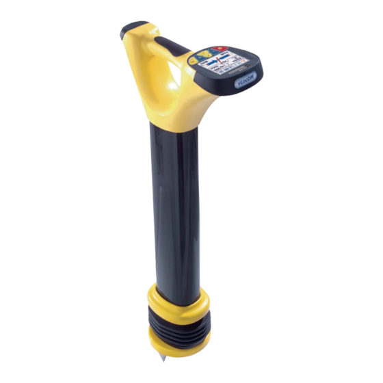
5 Receiver Functions and Operations Connectors Rechargeable Batteries (internal) Mini USB Port Pushbutton & Display Charging Socket Model# & Serial# Impact Protection AA Battery Pack (Removable) Carbon Fiber Reinforced Antennal Assembly Impact Protection Accessory & Charging Sockets Accessories Port Page 16 of 47... -
Page 23: Batteries
Charge time will vary depending on charge state of batteries but will typically be two hours. Setting User Preferences The vLocDM has many functions enabling it to be used for many applications and can be configured for different markets. For instance, it may be desirable for the depth readings to be displayed in imperial measurements or metric. By entering the user menu, it is possible to tailor the vLocDM to the requirements... -
Page 24: Setting Frequency Options
5 Receiver Functions and Operations Select the desired function by pressing the “+” or “-” pushbutton. The active function will be highlighted in red. To change the setting of the selected function, press the “return/ ” pushbutton. Note: Configurable options are: Return/ Pushbutton Speaker Volume Off, Low, Med, High Backlight Off, Low, High Frequency Enter Sub menu Frequency English Imp/Metric Meter, Feet Live - continuous update of DM current DM Current Live Static Static - One shot display of DM current per measurement Normal – the pitch remains the same but Power Sound... -
Page 25: Setting Locate Mode
5 Receiver Functions and Operations The receiver is capable of detecting a large number of frequencies. To simplify the operation of the equipment, it is possible to activate only frequently used frequencies. This is done by entering the user menu. The initial frequencies set at the time the unit is supplied are “Power”, “Radio” and the frequencies used by the transmitter purchased. See the transmitter section for suggestions of which frequency is best suited to specific applications. To select the frequencies you wish to use regularly – enter the setup menu by pressing and holding the “i” pushbutton for 2 seconds. Use the “+” and “-” to select the word “Frequency”... - Page 26 5 Receiver Functions and Operations Null Mode: Minimum signal over the pipe includes left/right guidance arrows. Sonde Mode: Largest signal over the Sonde. Note: Locator is held ACROSS the line of the Sonde. Also note two false signals each side of main signal. Broad Peak Mode: Increased sensitivity but sharpness reduced.
-
Page 27: Using The Vlocdm Receiver
6 Using the vLocDM Receiver Using the vLocDM Receiver Locating a Pipeline NOTE There are a number of antenna configurations available. Each has a particular response. However, for the purposes of simplicity the method below uses the generic “peak with left right arrows”. -
Page 28: Pinpointing
6 Using the vLocDM Receiver Pinpointing Before measurements are taken it is necessary to precisely pinpoint the pipeline. To do this, follow the following steps: Rotate the locator so that the compass line direction indicator is pointing North/South. Move the locator in the direction indicated by the arrow. Stop when the arrow changes to the opposite direction. -
Page 29: Taking Depth And Current Readings
6 Using the vLocDM Receiver Taking Depth and Current Readings To take any measurements it is first necessary to pinpoint the pipe as instructed in the section above “pinpointing”. Next, hold the receiver on the ground, vertically and with the handle in line with the pipe. Keep the receiver very stationary and press the “i” pushbutton. The display will show the following screen whilst the measurement is made 600mA 2.41m 3Hz6Hz 104m Please hold still ... After approximately 4 seconds the result will be displayed as below. 1.74 A 600mA 2.41m 3Hz6Hz 104m vLocDM Mapping Current... -
Page 30: Storing The Results
6 Using the vLocDM Receiver Storing the Results NOTE The DM current reading will continue to be updated approximately every second unless Static is chosen in the User setup of “DM Current”. This is done so that fluctuations in readings can be identified, allowing the user to wait until stable readings are shown before recording the result. - Page 31 6 Using the vLocDM Receiver Graph Screen Pushbutton Function Highlight each function in turn. A long press will enter the Review Screen. Increase zoom or scrolls right/up depending on button highlighted. Long press auto scale horizontal axis. Decrease zoom or scrolls left/down depending on button highlighted. Long press auto scale vertical axis Returns to the Locate Screen To clear the screen, press and hold the “-” pushbutton for 3 seconds. A message will be displayed. NOTE The horizontal scale of the graph defaults to equal spaces per record. So the graph assumes equal distance survey points.
-
Page 32: Using The A-Frame Fault Finder
The A-frame is used to pinpoint coating defects along the pipeline. It does this by measuring the voltage in the ground caused by the vLocDM signal current entering the pipe at a fault. It is necessary to make a physical/ electrical contact with the ground. -
Page 33: Fault Finding Method
6 Using the vLocDM Receiver 6.6.1 Fault Finding Method 1. Connect the transmitter as previously described. Select either 3Hz/6Hz/98Hz (ELF1) or 3Hz/6Hz/ 128Hz (ELF2) depending on mains frequency as previously described. Connect the A-frame as above. 6.6.2 Using the A-frame If the position of a defect has been identified by the vLocDM using the current gradient technique, start an A-frame survey approximately 20 meters before this point. Place the A-frame in the ground with the A-frame in line, the green pin pointing towards the suspected fault and directly above the pipe. The signal strength will be displayed, if the signal is strong enough an arrow will point forward and press the “+” pushbutton to save the... - Page 34 6 Using the vLocDM Receiver The locate icon (1) will still be active whilst using the A-frame and should be used to ensure the A-frame is used directly above the pipe. However, adjustments to sensitivity/mode/frequency can only be made when in the Locate Screen. It is possible to jump to the Locate Screen by pressing the “Return”...
-
Page 35: Using The A-Frame Where There Are Many Defects Such As Porous Coating
6 Using the vLocDM Receiver Sometimes it is not possible to gain access to the pipe position. If this is the case walking along the route of the pipe a few meters to one side can very often produce good results. This procedure is also useful where the pipe runs under “blacktop” which acts as an insulator preventing the A-frame from making a good connection to... - Page 36 6 Using the vLocDM Receiver Note the depth of the pipeline. Move approximately this distance to one side. Keep the orientation as above, walk along the section of pipeline taking readings at regular intervals. A typical result is shown below with the main defect being the largest reading. Note that the arrow will always point to the pipe, ie will not reverse unless the signal reduces to a level that cannot be processed correctly. A-frame Review Screen...
-
Page 37: Using An External Gps Data Logger
"Radio Mode" disable the internal Bluetooth device by entering the menu (long press i) and selecting disable "Bluetooth Search". Transferring Data to a PC To transfer data from the vLocDM to a PC requires the use of the dedicated Uploader applications program. The Uploader can be downloaded from the the Vivax-Metrotech website, www.vivax-metrotech.com. To upload a data file to PC double click on the vLocDM Uploader icon on your desktop. Connect a USB lead from the vLocDM to the PC. The program will detect the vLocDM locator and display “Locator detected”. -
Page 38: Interpreting Results
Moving the instrument whilst the unit is calculating the information will cause the strong earths magnetic field to induce an interfering signal into the sensors resulting in errors. The vLocDM must be kept absolutely still whilst it is taking measurements. -
Page 39: Checking For Distorted Fields
For best results the cross bonding should be disconnected for duration of the survey. Passing Vehicles The sensing devices used to detect the 3Hz vLocDM profiling signal are very sensitive to low frequencies. Vehicles passing very close to the receiver will disturb the earths magnetic field and cause distortion of the received signal. Try to take measurements when there is a gap in passing vehicles. In areas where traffic is passing, wait until three constant consecutive readings have been shown before saving result. -
Page 40: Downloading Data To A Pc
Downloading Data to a PC The vLocDM Uploader can be download from Vivax-Metrotech website,www.vivax-metrotech.com.This application allows the use of the vLocDM data in standard spread sheets such as Microsoft Excel. The application is compatible with Windows 2000, Windows XP and Windows Vista. Upload Log to PC and Clear Log in Receiver: 1. Once the application’s loaded to the PC a shortcut should appear on the PC desktop similar to the... - Page 41 8 Interpreting Results 3. Click on the “Attach Locator” icon. Do not check the Verbose boxes. The top box will indicate that the locator is detected. 4. Now click on “Log Upload” or “A-frame Upload” if the A-frame data log is required. The PC will request a folder location and .txt file name. Browse to your preferred folder location and allocate a name. Then press “open” to save the file. 6. The above screen will then be shown again. It is possible at anytime to clear the receiver’s log by clicking on the “Log Clear” icon. Be sure that the file has been saved before clearing the log. Press "Google Earth" to create a .kml Google Earth file. Importing a .txt File into an Excel Spreadsheet for Graphing and Analysis: Open the Excel application.
- Page 42 8 Interpreting Results The data is now in the form of an Excel spreadsheet and can be minupilated to create suitable graphs. In the example above, the Distance column is filled automatically, as the GPS option was used when data was collected. If GPS was not used, the distance between measurements will have to be inserted manually. It is advisable to insert a column in the spreadsheet for acumilated distance (This process is automatically done on some recent software revisions).
- Page 43 8 Interpreting Results The graph is drawn with a linear current x axis. If a logerithmic scale is required, right click on the x axis and select logerithmic from the options as below. Saving a Google Earth File 1. It is possible to save a DM Log file as a Google Earth .kml file. To do this, connect the locator to the PC as if getting ready to download a normal DM file. Instead of clicking on the “Log Upload” button, choose “Google Earth”. 2. The Application will ask where you want the file to be placed. Select a file location and save the file. A .kml file will automatically be created. 3. To launch a .kml file, double click on the selected file. If connected to the web and if Google Earth application is installed on the host computer, Google Earth will automatically launch and will zoom to the site location. Pins will indicate survey points. Clicking on a point will show measurement details for that point. Page 37 of 47...
-
Page 44: Interpreting Graphs
8 Interpreting Results Interpreting Graphs There are two types of graphs that can be plotted. These can either be plotted. Linear Logarithmic In either case, it is important to look at the trend of the graph rather than individual points. This is because the signals radiating from a pipe can be affected by many external influences such as: • passing cars • ground currents from stray currents • ground currents from the transmitter • slight movements of the receiver This is just a few examples, the list is probably endless. The intention is to identify changes in current which signify a defect. So if we were to look at a small section of graph it is, incorrectly, possible to interpret fluctuations as a defect. See diagram below. -
Page 45: Care And Maintenance
Always dry the equipment before storing. Checking Functionality The vLocDM system can be checked using a simple test procedure. It requires an area clear of pipes and cables and free from metallic structures such as metal tanks, metal railings and reinforced concrete. A 40m square loop of wire needs to be set out on the ground with a non metallic structure placed at 1m above the cable and at the mid point of one of the straight sections. -
Page 46: Data Sheet
10 Data Sheet Data Sheet 10.1 vLocDM Receiver Typical Applications Item Parameter Description Pipeline defect mapper receiver • Locating and pinpointing coating defects on buried pipelines • Profiling the CP current distribution on a pipeline network Uses • Identification of short circuits from pipelines to other structures • Long distance pipeline location Receiver Assembly Item Parameter • Carbon fiber reinforced antenna tube Construction • High impact thermoplastic (ABS) injection molded housing • ABS foot molding containing magnetometer Weight 7.5lbs (3.4kg) Dimension 11.7” (L) x 5.5” (W) x 30.4” (H) (298 (L) x 140 (W) x 772 (H) mm) Display Type Sharp TFT LCD ¼ VGA color display, 3.52” (89mm) - Page 47 10 Data Sheet Item Parameter • USB data cable • 100-240V AC mains charger • Soft carry bag for vLocDM receiver Standard • User handbook Accessories • GPS (external) • Bluetooth (internal) • A-frame • Auxilliary rechargeable battery pack (fits in place of alkaline batteries) charged externally • Vehicle charging lead • Sondes (waterproof self-contained transmitters for use in pipes & ducts) • D18-33-SR44 - 0.75” (18mm) (Dia.) x 3.1” (80mm) (L), 33 kHz, range Accessories 12ft (4m), 2 x button cell batteries (Option) • D38-33-AA – 1.5” (38mm) (Dia.) x 4.1” (105mm) (L), 33 kHz, range 15ft (5m), 1 x AA battery • D64-33-LR61 – 2.5” (64mm) (Dia.) x 7.3” (186mm) (L), 33 kHz, range 24ft (8m), 1 x LR61 battery • D23F-512-AA / D23F-640-AA – 1” (23mm) (Dia.) x 18” (456mm) (L), 512Hz or 640Hz, range 20ft (7m), flexible Sonde in 3 sections for use in cast iron pipes as well as non metallic pipes, 1 x AA battery Operational Item Parameter • Signal strength - moving bar graph & numeric value • Mode indication (“Peak”, “Null”, “Broad Peak”, “Sonde”, and “Peak with proportional left/right arrows” location) • Proportional left/right indication...
- Page 48 3. Units of measure (feet/meter) 4. Power Mode – 50Hz or 60Hz environments 5. Sound (Pitch) – normal/modulated Configuration 6. Favorite mode selection 7. Language 8. Continuous depth option 9. Continuous signal current option 10. Speaker level 11. Backlight level vLocDM (magnetometer) frequencies: 3Hz/6Hz , 4Hz/8Hz vLocDM related locate frequencies: 98Hz, 128Hz, 512Hz, 640Hz General locating frequencies included as follows: Power 50 (50+150+250Hz) 460Hz 8.44 kHz (8,440Hz) Power 60 (60+180+300Hz) 480Hz 9.5 kHz(9,500Hz) Radio Mode (22.1 kHz) 484Hz 9.82 kHz(9,820Hz)
- Page 49 10 Data Sheet Item Parameter • 1000 data point storage Data Storage • Download of stored data to specific strategic partners’ applications or to PC via and Data Handling Vivax-Metrotech desktop application for detailed analysis in dedicated analysis software or standard spread sheets such as Microsoft Excel. Gain Control Press “+” or “-” pushbutton once to return to mid scale Locate pinpointing accuracy: • up to 9ft (3m) – 5% of depth • over 9ft (3m) – 10% of depth Depth measurement accuracy: • 5% of depth Performance using Current measurement accuracy:...
- Page 50 10 Data Sheet Item Parameter Uses Tracks up to 32 satellites Update Rate Battery Life Lithium-ion battery lasts for 15 hours of use Operating : 14°F to 140°F (-10°C to 60°C) Temperature Range Storage : -4°F to 140°F (-20°C to 60°C) Operation Humidity 5% to 95% no condensing Non DGPS(Differential...
- Page 51 3A with three or four simultaneous frequencies. Uses 2 Rotary/Push control knobs to select: • Frequency Controls • Output level • Information • ACTIVE/STANDBY pushbutton • One On/OFF pushbutton Compatible with vLocDM Receiver D. Environmental Item Parameter Operating : -4ºF to122 ºF(-20ºC to 50ºC) Temperature Range Storage : -40ºF to 140ºF (-40ºC to 60ºC) Weather Proof...
-
Page 52: Glossary
11 Glossary Glossary Active Locate A locate where a transmitter is used to apply a signal to a buried pipe or cable, the position of which is then located by a receiver tuned to the same frequency. A signal applied by the locator transmitter to a buried line. Typical this is a very precise Active Signal frequency. Attenuation The reduction of an electromagnetic signal from a pipe or cable. - Page 53 11 Glossary Sonde A small transmitting coil which may be built into a product such as a sewer camera or packaged as a small self contained battery powered transmitter. A receiver tuned to the same frequency can locate the position of the Sonde and hence whatever it is attached to or in. Frequently used for locating sewer cameras, and the non metallic pipes.
- Page 54 Notes: Vivax-Metrotech Corporation, 3251 Olcott St., Santa Clara CA 95054, USA Website: www.vivax-metrotech.com...
Need help?
Do you have a question about the vLocDM and is the answer not in the manual?
Questions and answers