Vivax Metrotech vLoc3-9800 User Handbook Manual
Hide thumbs
Also See for vLoc3-9800:
- User handbook manual (20 pages) ,
- User handbook manual (54 pages)

Related Manuals for Vivax Metrotech vLoc3-9800


Summary of Contents for Vivax Metrotech vLoc3-9800
- Page 1 User Handbook (English Edition) Version 1.0 P/N: 4.04.000107 rrobertson@wctproducts.com | 13309 Beach Ave. Marina del Rey, CA 90292 Phone: 800-WCT-PROD (928-7763) | Fax: 310-306-9343 | www.wctproducts.com...
- Page 2 rrobertson@wctproducts.com | 13309 Beach Ave. Marina del Rey, CA 90292 Phone: 800-WCT-PROD (928-7763) | Fax: 310-306-9343 | www.wctproducts.com...
-
Page 3: Table Of Contents
Table of Content General Safety & Care Information ........................1 Who Can Use This Equipment .........................1 Work-site Safety ............................1 Equipment Safety .............................1 Batteries and Environmental Safety ......................1 1.4.1 Alkaline Batteries .........................1 1.4.2 Nickel-Metal Hydride Batteries (rechargeable) ................1 1.4.3 Lithium-ion Batteries (rechargeable) ...................2 1.4.4 Lithium-metal Batteries (non-rechargeable) ................2 1.4.5... - Page 4 3.7.1 Auto Left/Right Mode (Active modes only i.e. not available in Power or Radio modes) ....13 3.7.2 Manual Left/Right Mode (Active modes only i.e. not available in Power or Radio modes) ..14 3.7.3 Manual Peak Display Mode .......................14 Information Pushbutton - Depth & Current .....................15 Passive and Active Location ........................16 3.9.1 Passive Locating ........................16...
- Page 5 Transmitter Battery ..........................56 6.5.1 Replacing Alkaline Batteries ......................56 6.5.2 Rechargeable Batteries ......................56 6.5.3 Battery Charging and Disposal ....................56 Using the vLoc3-9800............................57 Using the Accessories ..........................57 7.1.1 Using the LPC Separation Filter ....................57 7.1.2 Using the Analogue A-frame Fault Finding Accessory...............57 7.1.3 Using the vLoc3 Remote Antenna .....................61...
- Page 6 LPC Separation Filter ..........................64 Receiver Vehicle Charging Lead ......................65 Sondes..............................65 Clamps..............................65 Clamp Extension Rod ..........................65 8.10 Ground Extension Spool .........................66 8.11 Banana Plug Adapter ..........................66 8.12 Loc3-5Tx and Loc3-10Tx Charger/PS ....................66 8.13 Loc3-5Tx and Loc3-10Tx Rechargeable Battery Tray ................66 8.14 vLoc3-MLA ..............................66 Glossary ................................67 rrobertson@wctproducts.com | 13309 Beach Ave.
-
Page 7: General Safety & Care Information
General Safety & Care Information General Safety & Care Information Who Can Use This Equipment ● This equipment must only be used by people suitably trained in the use of pipe and cable locators. Work-site Safety ● Use your company’s, or other applicable safety code and rules when using this equipment. ●... -
Page 8: Lithium-Ion Batteries (Rechargeable)
General Safety & Care Information ● Do not charge batteries for prolonged periods of time without using the locator for at least ten minutes. Charging for prolonged period of time could overcharge the battery, reduce the battery life and in extreme circumstances can cause damage to the locator and fire. -
Page 9: Care When Interpreting The Information Provided By The Locator
General Safety & Care Information Care when Interpreting the Information provided by the Locator ● Like all locators – this instrument is locating and providing depth and current readings based on electromagnetic signals that radiate from the buried cable or pipe. In most cases these signals will enable the locator to pinpoint both position depth and current correctly. -
Page 10: Service & Support
Service & Support Service & Support Serial Number and Software Revision Number Always quote your receiver and transmitter model number, serial number and software revision number when requesting product support. They can be found as follows: (for reference only). Model & Serial Number NOTE The transmitter model &... -
Page 11: Distributors And Service Centers Closest To You
Service & Support Distributors and Service Centers Closest to You: World Headquarters, United State of America Central/South America and the Caribbean Vivax-Metrotech Corporation Ventas para América Latina 3251 Olcott Street, 3251 Olcott Street, Santa Clara, CA 95054, USA Santa Clara, CA 95054, USA Website : www.vivax-metrotech.com T/Free : 800-624-6210... -
Page 12: Vloc-9800 Receiver
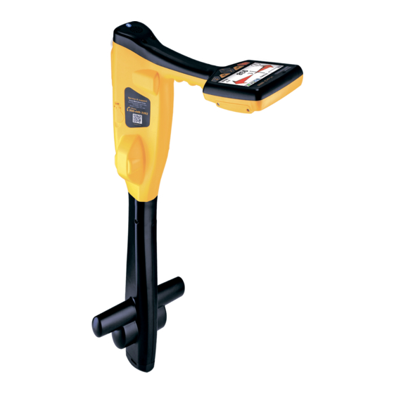
Receiver vLoc3-9800 Receiver vLoc3-9800 Receiver Overview The vLoc3-9800 is a precision location system designed to meet the needs of utility companies and their contractors. The following describes the features and use of the receiver: vLoc3-9800 receiver Mini-USB cable Li-ion battery... -
Page 13: Charging The Receiver Batteries
Receiver Charging the Receiver Batteries The vLoc3-9800 can be used with either alkaline batteries or an interchangeable rechargeable battery pack. The central illuminated section within the battery icon indicates the amount of charge remaining. ● Green center indicates rechargeable batteries ●... -
Page 14: Vloc-9800 Receiver Keypad
Short press = enter information screen Long press = enter User Set-up options The vLoc3-9800 has two main operational screens, “Peak Detect” and “Left/Right”. These are described in detail later in the manual. The following describes the elements displayed on the screens. - Page 15 Receiver Battery Indicator. Blue = Alkaline Batteries, Green = Rechargeable batteries. When batteries are low, the symbol will have a red section and will flash slowly indicating the battery has a very low charge. Speaker volume indicator. Enter “User menu” to alter volume.
-
Page 16: Setup Menu
Receiver Setup Menu The vLoc3 9800 has several features that can be switched on and off. These features are accessed through the user menu. Switch on the unit by pressing and holding the On/Off key until the start-up screen appears. The start-up screen can be configured to the user’s preference and is described later in the manual. -
Page 17: Language
Loc3-10Tx. Self-Test The vLoc3-9800 has a self-test feature. The test confirms that the equipment is fit for use and calibration has not drifted from its expected settings. To undertake the test, first find an area free from excessive interference such as overhead fluorescent lighting, large transformers etc. -
Page 18: Warnings
Receiver Select “Self-Test” from the user menu and press the “Return” button. The test will self-start. Keep the equipment stationary while the test is completed. After a short while the unit will report a Passed or Failed. Examples are below:... -
Page 19: Locating Mode
MyLocator3). Warnings can also be switched off in the User Set-up Menu. Locating Mode The vLoc3-9800 receiver has an array of antennas; these can be toggled through different modes to provide different responses to the signals radiating from the buried pipes and cables. Use a long press on the button to toggle through the available modes. -
Page 20: Manual Left/Right Mode (Active Modes Only I.e. Not Available In Power Or Radio Modes)
Receiver 3.7.2 Manual Left/Right Mode (Active modes only i.e. not available in Power or Radio modes) Manual 25dB 33kHz 0.73m 219mA In the Manual Left/Right mode the sensitivity is set by pressing the “+” and “-” pushbuttons. The gain setting can be seen in the top left of the screen. -
Page 21: Information Pushbutton - Depth & Current
Receiver When using the manual peak display mode the relative signal levels become apparent, aiding identification of the target line. The direction of the line can be determined by rotating the locator on its axis. When the signal is strongest the line is passing exactly forward/backwards. -
Page 22: Passive And Active Location
Receiver Datalogging It is possible to save the data on the info screen to the internal datalog. Pressing the “+” saves the data, pressing the “-” key rejects the data and returns to the locate screen. The number of logs stored in the device is also indicated. -
Page 23: Active Locating
Receiver 3.9.2 Active Locating Active locating uses a transmitter to apply a very precise frequency to a pipe or cable. A receiver, tuned to that frequency, is then used to detect that signal. Active locate frequencies can be applied by direct connection, clamp or induction. -
Page 24: Clamp
Receiver 3.10.2 Clamp This is used when applying the transmitter signal to cables carrying hazardous voltages, or cables where access to the metallic conductor is not possible, or desirable. The “Clamp” mode is selected automatically when the clamp is plugged into the transmitter. -
Page 25: Searching An Area
Receiver When using the “Induction” mode to apply a signal to a line, it is best that a minimum distance of 50ft (20m) is maintained. This is because the transmitter will transmit signal through the air which will interfere with signals from the cable, resulting in incorrect information. -
Page 26: Pinpointing & Confirming The Buried Line
Receiver 3.10.6 Pinpointing & Confirming the Buried Line Marking the exact position of the buried line is generally called pinpointing. Pinpoint the line before marking its position. Place the receiver in “Manual Peak” or “Left/Right” mode, pass the blade of the receiver across the path of the cable and identify the position as indicated by the largest signal or as indicated by the Left/Right indicator. -
Page 27: Distorted Fields
Receiver Distance A to B = Depth (D) ● Measuring the signal current. Pinpoint the line as for measuring depth. The current can be displayed by briefly pressing the “i” pushbutton. Depth and current will be displayed, the signal from the transmitter will attenuate with distance. The further from the transmitter the less signal will radiate from the buried line. - Page 28 Switch on the Sonde by connecting the battery. Connect it to the pushrod and place it in the start of the pipe run. Switch on the vLoc3-9800 and select Sonde mode using long presses on the “Return” button. The Sonde icon will now be visible on the screen.
- Page 29 Now sweep left and right over the Sonde to obtain a second peak. Note that there are no ghost signals when sweeping left to right over the Sonde. Finally check that the vLoc3-9800 is in line with the Sonde by rotating it on its axis to obtain a peak signal. The vLoc3-9800 is now over the Sonde and in line with it.
-
Page 30: Data Logging
Data Logging Data Logging The vLoc3-9800 has an internal memory that can be used to store locator data. Available storage size is 4 Gigabyte which relates to many thousands of records. The records are user initiated. These are records stored by the user whenever the “+” button is pressed when in the “Information”... -
Page 31: Bluetooth
Data Logging Auto 51°13′57.58200′′N 686’8’’ 2°30′44.74800′′W 0’5” 18.2mA The screen will then automatically revert to the locate or accessory screen. The data log can also be deleted from the info screen. From the info screen press and hold the “- “key. The message below will be shown. -
Page 32: Pairing With External Gps/Dataloggers
GPS (Global Positioning System)/GNSS (Global Navigation Satellite System). The vloc3-9800 can utilize location data an external GPS/GNSS. The vLoc3-9800 needs to be paired with an external device (See previous section on Bluetooth devices). -
Page 33: Mylocator3
Follow the instructions to download and install the application. MyLocator3 A “MyLocator3” icon will appear on the computer desktop. Connect your vLoc3-9800 to your computer via the mini USB connector which can be found under the battery cover flap. Launch MyLocator3 by double clicking on the icon. 4.3.2 MyLocator3’s Basic Operation... -
Page 34: Application Update
Data Logging 4.3.2.2 Application Update Every time the MyLocator3 Application is started its version number is checked against the latest version available on the Vivax- Metrotech server and the user is notified if an update is available as shown below. This feature will only be available if the computer is “on line”. -
Page 35: Toolbar
Toolbar The vLoc3-9800 locator can be configured so that features can be switched on or off. This enables the user to tailor the instrument to meet the needs of their application while keeping the user interface uncluttered. The toolbar at the top of the screen enables the user to create configurations. -
Page 36: Data Logging
Data Logging 4.3.4 Data Logging Clicking on the Data Logging tab will display information about the state of the attached locator’s data log contents. The data log contents can be stepped-though by using the controls on the left-hand side. The user can upload a selection of logs from the locator to the PC by using the controls in the upper rightt-hand side. -
Page 37: Frequencies Page
Data Logging The start-up screen will be displayed in the application. The Download button can be used to set the splash screen immediately or the image can be sent to the locator along with the rest of the configuration by pressing the “Write Configuration” button. To remove a start-up screen and revert to the default Vivax-Metrotech screen click on the “Clear”... -
Page 38: Menu Settings
Data Logging 4.3.7 Menu Settings The Menu Settings page allows the user control over which menu items appear on the locator and also the initial setting of the menu item when the locator is first used after configuration. The menu items with a right pointing arrow can be expanded to reveal further sub-menu items. -
Page 39: Advanced Features
Data Logging 4.3.8 Advanced Features The Advanced Features are available to those users in possession of a USB security dongle. If a dongle is attached to the PC then its level will be displayed on the MyLocator3 status bar. 4.3.8.1 Supervisor Lockouts This feature is available to anyone with a dongle, contact Vivax-Metrotech, or your local distributor for the purchase of a dongle. -
Page 40: Loc3-10Tx Transmitter
Loc3-10Tx Transmitter Loc3-10Tx Transmitter Loc3-10Tx Transmitter Overview The Loc3-10Tx transmitter is a rugged portable transmitter powered by alkaline “D” cells or Li-ion rechargeable batteries. The following describes the features and uses of the transmitter. Loc3-10Tx transmitter Ground stake Direct connection lead 12 x D cell alkaline batteries Alkaline battery tray Mini-USB lead... -
Page 41: Pushbutton
Loc3-10Tx Transmitter *External Voltage Warning The transmitter checks the line when connected. If the line is carrying voltages in excess of 25V, it will display the “high voltage” warning icon and not allow the transmitter to operate. In addition the transmitter is protected by a 1.5A/250V fuse in the event of excessive voltage or voltage spikes on the line. -
Page 42: Transmitter Battery
Loc3-10Tx Transmitter The connection block consists of: ● Output (XLR) socket – for the direct connection lead and clamp. ● Charger socket (to charge rechargeable battery pack – the charging socket is present even if rechargeable batteries have not been purchased). ●... -
Page 43: Rechargeable Batteries
Loc3-10Tx Transmitter WARNING Alkaline Batteries – insert alkaline batteries (x12) as shown: 5.2.3 Rechargeable Batteries ● Do not attempt to replace the rechargeable batteries or remove battery covers – return to Vivax-Metrotech or a Vivax- Metrotech approved service centers for replacement. WARNING Use only Vivax-Metrotech recommended charger. -
Page 44: Transmitting Modes
Loc3-10Tx Transmitter Transmitting Modes The transmitter has three transmitting modes, which are selected automatically. 5.3.1 Induction Mode This uses an internal antenna to induce a locating frequency onto the target pipe or cable (line). “Induction” mode is automatically selected if no connection accessories are plugged into the “output socket”. An icon indicating “Induction” mode shows on the display. -
Page 45: Clamp Mode
Loc3-10Tx Transmitter Wherever a direct connection can be safely made without the risk of injury, damage to customer’s plant, or the transmitter, it is the best way of applying the transmitter’s signal. The coupling of the transmitted signal to other pipes and cables in the area will be much less than with induction, although where commonly bonded systems are encountered –... -
Page 46: Most Used Frequencies Feature
Loc3-10Tx Transmitter ● 8 kHz direct connection – 10 watt ● 33 kHz direct connection – 10 watt ● 65 kHz direct connection – 1 watt. ● 83.1 kHz, 131 kHz direct connection – 1 watt (depending on region). ● 200 kHz direct connection – 1 watt (depending on region). ●... - Page 47 Loc3-10Tx Transmitter The advantage of this feature is that user can work with only their preferred frequencies, instead of having a whole list of frequencies to scroll through. To enter the “Frequency Menu” proceeds as follows: Press the “i” pushbutton four to six times (based on the mode that transmitter is in) until reaching the “Frequency menu” sub-menu.
-
Page 48: Multi-Frequency Mode For Direct Connection
Loc3-10Tx Transmitter Pressing the “+” or “-” pushbuttons, you can scroll up or down through the available frequencies. Once the wanted frequency is inside the box, press “f” pushbutton to select or deselect the frequency. An “x” will appear in the box for a selected frequency. -
Page 49: Remote The Operation Of Transmitter
Loc3-10Tx Transmitter Press “f” pushbutton to move the box down and the “+” and “-” pushbuttons to select the second frequency. Multi Freq Setup 32.8kHz 83.1kHz 200kHz Repeat step three to select the third frequency if needed. Press “i” pushbutton to return to main display. On the main display, “Multi” will appear indicating the multi frequency mode is active. - Page 50 Loc3-10Tx Transmitter Press the “+” key to enter the Receiver Link menu. R E C E I V E R L I N K E N A B L E B A C K Press the “+” or “-” key to highlight the “ENABLE” option, then press the “F” key to start the process. The display will show the message “WAIT”...
- Page 51 Loc3-10Tx Transmitter Transmitter Link Menu Meter Imp/Metric Transmitter Link Disabled Continuous info. GPS source Internal Bluetooth Pairing Transmitter Link Transmitter Control Select the “Transmitter Link”. Check that the radio module is enabled. If not, press the return button to enable the Transmitter Link.
- Page 52 Loc3-10Tx Transmitter Also shown is the: Radio link signal strength, in this case 40%. Output mode, in this case direct connection. Output current, in this case 100mA. Beeper volume setting, in this case level 2. Transmitter battery level. Use the Information button to navigate/Exit back to the locate screen. When in the Locate screen the status of the Link is displayed in the Status bar.
-
Page 53: Loc3-5Tx Transmitter
Loc3-5Tx Transmitter Loc3-5Tx Transmitter Loc3-5Tx Transmitter Overview Loc3-5Tx transmitter Ground stake Direct connection lead 8 x D cell alkaline batteries Alkaline battery tray Mini-USB lead 6.1.1 Display 8.19 kHz 1 0 2 Mode Indication Icon Output Setting (Step) (filled box indicates current level has been reached, empty box indicates requested High Voltage Warning* (output is enabled for high current level has not been achieved) -
Page 54: Pushbuttons
Loc3-5Tx Transmitter *External Voltage Warning The transmitter checks the line when connected. If the line is carrying voltages in excess of 25V, it will display the “high voltage” warning icon, and not allow the transmitter to operate. In addition, the transmitter is protected in the event of excessive voltage or voltage spikes on the line. -
Page 55: Removing The Battery Tray
Loc3-5Tx Transmitter 6.2.1 Removing the Battery Tray Pull out bottom of catch 6.2.2 Replacing the Alkaline Battery ● To access batteries – undo the two latches that are locking the battery cover. ● To remove batteries – remove the battery holder from the inside of the unit. ●... -
Page 56: Rechargeable Battery Pack Charging And Disposal
Loc3-5Tx Transmitter 6.2.5 Rechargeable Battery Pack Charging and Disposal Follow the instructions in the General Safety & Care section portion of this document. Only use the battery charger supplied with the battery. Using a non-approved charger may damage the battery pack and could cause overheating. -
Page 57: Direct Connection Mode
Loc3-5Tx Transmitter 6.3.2 Direct Connection Mode By plugging in a connection lead to the output socket, “Direct connection” mode is selected. An icon confirming this is shown on the display. The wave in the icon fluctuate when the transmitter is transmitting. The direct connection lead consists of two cables, one (red clip) must be connected to the conductor being located, the other (black clip) to a suitable ground (a ground stake is provided with the transmitter). -
Page 58: Frequencies
Loc3-5Tx Transmitter The clamp is a specialized inductive device (sometimes known as a toroid or coupler). All clamps are optimized to work at specific frequencies. In most cases clamps are designed to be used at frequencies generally between 8 kHz and 200 kHz. The transmitter will only allow the selection of a suitable range of frequencies for your clamp. -
Page 59: Most Used Frequencies (Frequency Selection) Feature
Loc3-5Tx Transmitter NOTE: The output current is shown in large characters on the display – to increase or reduce the power output press “+” or “-”. The vertical bar graph at the bottom of the display indicates which of the five current output steps is being used. If the transmitter can supply the requested current, the bar will turn black. -
Page 60: Multi Frequency Mode For Direct Connection
Loc3-5Tx Transmitter In Clamp mode, Frequency Menu Bluetooth Menu LCD Contrast Voltage Volume Screen will show a list of frequencies available, with the central one in a box. Frequency Menu SD-USA FF Low FF High Pressing the " " or " "... - Page 61 Loc3-5Tx Transmitter Frequency Menu Bluetooth Menu LCD Contrast Multi Frequency Resistance Voltage Volume Pressing the " " and " " pushbuttons to scroll through the available frequencies and bring the wanted one in the first box. Multi Freq Setup 32.8kHz 83.1kHz 200kHz Press "f"...
-
Page 62: Transmitter Battery
Loc3-5Tx Transmitter Transmitter Battery 6.5.1 Replacing Alkaline Batteries ● Replace with new batteries of the same type, be sure not to mix old and new batteries. ● Do not use rechargeable batteries in the alkaline battery tray. Ensure that batteries are inserted the correct way (see label "... -
Page 63: Using The Vloc3-9800
Using the vLoc3-9800 Using the vLoc3-9800 Using the Accessories 7.1.1 Using the LPC Separation Filter The LPC separation filter (LPC) is used to safely inject a trace tone to a live cable via a domestic mains socket, so that the cable can be traced from the premises to the connection in the street. - Page 64 Using the vLoc3-9800 Fault finding requires a non-standard signal “8kHz FF” To detect a damaged section, the line should be isolated and have all ground bonding removed. This will ensure that the ground fault is not masked by deliberate bonding to ground. The A-frame cannot distinguish between these two situations.
- Page 65 Using the vLoc3-9800 26 dB 8KFF Image for reference only and may differ from actual image Remove the plastic spike covers from the A-frame. Walk along the route of the line placing the spikes of the A-frame in the ground (with the green leg pointing away from the transmitter connection point) every two or three paces.
- Page 66 Using the vLoc3-9800 WARNING Always disconnect or isolate target/faulty/suspected cables before connecting the transmitter to it. Never attach the transmitter to live cables. If it is suspected that there is just one fault, insert the A-frame approximately one meter from the earth stake.
-
Page 67: Using The Vloc3 Remote Antenna
Using the vLoc3-9800 7.1.3 Using the vLoc3 Remote Antenna The remote stethoscope antenna can be used to help trace a particular cable on a cable tray or where cables are bunched together. Methods: Connect a signal to the cable to be identified. The remote stethoscope functions has an operational frequency range of 512Hz up to 200 kHz, but low frequencies should be a preference in this application as they are less likely to leak or bleed over to other cables. - Page 68 Note the signal reading of each cable. The one with the largest reading is likely to be the target cable. 10. If necessary, adjust the sensitivity of the vLoc3-9800 so that the signal is within the operating section of the bar graph.
- Page 69 Using the vLoc3-9800 Method: Connect the transmitter to two of the cores of the cable. At the far end, short together these two conductors making a loop. Set the transmitter to a low frequency such as 640Hz and set the output to maximum.
-
Page 70: Accessories & Options
Accessories & Options Accessories & Options A-frame The A-frame accessory is used to detect ground faults on pipes and cables. In the case of pipes, the faults consist of coating defects. In the case of cables, faults are usually caused by insulation damage allowing the metallic sheath (or internal conductor) to become in contact with the ground. -
Page 71: Receiver Vehicle Charging Lead
Accessories & Options Receiver Vehicle Charging Lead 12ft (4m) long lead to charge the receiver’s battery (Lithium-ion) while on the move. It is preferable to connect the charger to a cigarette lighter socket that is permanently live. However, do not leave connected to the receiver for excessively long periods Sondes D38-33-AA Sonde ●... -
Page 72: Ground Extension Spool
Accessories & Options The extension rod is fitted with a 10mm screw thread. This male thread will screw into the handle of the signal clamp and will enable the clamp to be attached too hard to reach cables such as in manholes or overhead cables. The extension rod is also fitted with a female thread in the handle which enables the rods to be fitted together to further extend the range. -
Page 73: Glossary
Accessories & Options Glossary Active Locate A locate where a transmitter is used to apply a signal to a buried pipe or cable, the position of which is then located by a receiver tuned to the same frequency. Active Signal A signal applied by the locator transmitter to a buried line. - Page 74 Notes: rrobertson@wctproducts.com | 13309 Beach Ave. Marina del Rey, CA 90292 Phone: 800-WCT-PROD (928-7763) | Fax: 310-306-9343 | www.wctproducts.com...
Need help?
Do you have a question about the vLoc3-9800 and is the answer not in the manual?
Questions and answers