
Related Manuals for Vivax Metrotech VM-500 Series


Summary of Contents for Vivax Metrotech VM-500 Series
- Page 1 VM-500 Series and VM-880 User Handbook VM-550, VM-560, VM-585, VM-880 (English Edition) Version 1.0 P/N:4.04.000222...
- Page 3 General Safety & Care Information Who Can Use This Equipment • This equipment must only be used by people suitably trained in the use of pipe and cable locators. Work-site Safety • Use your company’s or other applicable safety codes and rules when using this equipment. •...
- Page 4 5. General Rules regarding Disposal of Batteries • Never disassemble a battery or battery pack. • Never dispose of in a fire or water. • Dispose of batteries following your company’s work practice/environmental standards, the prevailing laws, or recognized best practice. Always dispose of batteries responsibly. 6.
-
Page 5: Table Of Contents
2. VM-500 Series Receivers ..................3 2.1 VM-500 Series Receivers Overview ............... 3 2.2 The Receiver Batteries ................... 5 2.3 The VM-500 Series Keypad for Utility Locate Mode ........5 2.4 A Peak Locator (response) ................6 2.4.1 Peak Response Locator .............. -
Page 7: Service & Support
Service & Support 1. Service & Support 1.1 Serial Number and Software Revision Number Always quote your receiver and transmitter model number, serial number, and software revision number when requesting product support. They can be found as follows: (for reference only). VM-550, VM-560 and VM-585 Locator Kits VM-880 Ferrous Metal Detector Model &... -
Page 8: Distributors And Service Centers Closest To You
Service & Support 1.2 Distributors and Service Centers Closest to You: Worldwide Sales Offices and Service Centers World Headquarters, United States of America Central/South America and the Caribbean Vivax-Metrotech Corporation Ventas para América Latina Ventas para América Latina 3251 Olcott Street, 3251 Olcott Street, 3251 Olcott Street, Santa Clara, CA 95054, USA... -
Page 9: Vm-500 Series Receivers
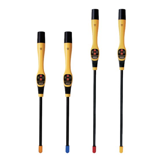
VM-500 Series Receivers 2. VM-500 Series Receivers 2.1 VM-500 Series Receivers Overview This user manual covers the VM-550, VM-560, VM-585 Utility locators, the metal detection mode of the VM-585 Receiver and the VM-880 Metal Detector. For the most part, the features and functions of these receivers are the same. Where different, they will be noted. - Page 10 VM-500 Series Receivers VM-880 Ferrous Metal Detector VM-880 Receiver 2 x AA Battery Holder Mini USB Cable User Handbook Carry Bag The VM-550, VM-560 and VM-585 Series Receivers LCD in Utility Locate Mode Battery level indicator Speaker level indicator Percentage signal level...
-
Page 11: The Receiver Batteries
Federal/State and local regulations. Never dismantle batteries, put them in a fire, or get wet. 2.3 The VM-500 Series Keypad for Utility Locate Mode This section covers the VM-550, VM-560 and VM-585 in Utility location modes. The VM-585 and VM-880 Metal Detection Mode is covered in section 6.0 of this manual. -
Page 12: A Peak Locator (Response)
VM-500 Series Receivers 2.4 A Peak Locator (response) The VM series receivers are Peak response locators. 2.4.1 Peak Response Locator Two horizontal antennas provide a “Peak” or maximum signal response over the buried line's center. This is an accurate locating method as both horizontal antennas are used to provide a clearly identifiable “Peak.”... -
Page 13: Using The Vm-500 Series Receivers
Using the VM-500 Series Receivers 3. Using the VM-500 Series Receivers 3.1 Passive Locating Power signals - are created by mains power running in the supply cables. These signals are 50 or 60Hz, depending on the country. For instance, the UK is 50Hz power, but the USA has 60Hz. -
Page 14: Active Locating:- Applying The Transmitter
Using the VM-500 Series Receivers Locating a Cable in the Power (50/60Hz) Mode Hold the locator vertically in the area that is required to be searched. Then, press the “+” or “-” pushbuttons to set the gain so that the bar graph reads approximately 50%. -
Page 15: Direct Connection
Using the VM-500 Series Receivers For frequencies below 45 kHz, authorities such as the FCC allow higher power output to be used; for frequencies of 45 kHz and above, power output for this type of equipment is restricted to 1 watt. Therefore more power is available when lower frequencies are used. -
Page 16: Signal Clamp (For Frequencies Above 8Khz)
Using the VM-500 Series Receivers It is sometimes impossible to find a suitable projection to apply the connection clip to a ferrous material. If this is the case, use a magnet to contact the line and then clip the red clip to the magnet. A good example of this is to make a connection to a street lighting circuit. - Page 17 Using the VM-500 Series Receivers Clamp Extension Rod A useful accessory to the clamp is the extension rod: Male thread for Remove the yellow handle screwing into a clamp to access the female threads to add another extension rod The extension rod is fitted with a 10mm threaded male stud. This male thread screws into the handle of the signal clamp to extend the distance of the clamp.
-
Page 18: Induction (For Frequencies Above 8Khz)
Using the VM-500 Series Receivers 3.2.3 Induction (for frequencies above 8kHz) When no direct connection lead or signal clamp is connected, the transmitter will automatically start to radiate (induce) a signal around the transmitter. These signals will penetrate the ground and couple onto buried lines. The signal will then travel along the line, which can be detected with the VM series receivers. -
Page 19: Locating Active Signals
Using the VM-500 Series Receivers 3.3 Locating Active Signals Apply the transmitter signal to the line. Select a desired locate frequency matching the transmitter. Adjust the sensitivity control so that the display indicates approximately 50%. Keeping the VM receiver vertical, move to the side slightly. If the bar graph increases, you are moving toward the line. -
Page 20: Searching (Sweeping) An Area In The Peak Mode
Using the VM-500 Series Receivers 3.4 Searching (sweeping) an Area in the Peak Mode Buried utilities may be parallel to each other and frequently they cross the area being searched at various angles and depths. As the locator antenna's response is directional, it is important to search the area in the same or similar pattern as shown. -
Page 21: Distorted Fields
Using the VM-500 Series Receivers Now press the depth measurement/frequency selection button. There will be a short delay before a depth estimate is displayed. 8.19k 2 feet 7 inches NOTE The depth measurement is an approximation. Depth indications can be affected by field distortion caused by adjacent utility lines or direction and depth changes. -
Page 22: The Vm-500 Series Transmitters
This section of the manual covers the VM-550FF and VM-560FF transmitters. 4.1 VM-500 Series Transmitter Overview The VM-500 series transmitters are rugged portable transmitters powered by alkaline “D” cells or Li-ion rechargeable batteries. The following describes the features and uses of the transmitter. -
Page 23: Transmitter Batteries
The VM-500 Series Transmitters 4.2 Transmitter Batteries The VM series transmitters use 4 x D cell alkaline batteries. An option Li-ion battery kit is also available. The low battery status is indicated by the Output Low/High LED flashing. VM Transmitter Battery Compartment... -
Page 24: Optional Li-Ion Transmitter Battery
The VM-500 Series Transmitters 4.2.2 Optional Li-ion Transmitter Battery Charging the Li-ion Battery Remove the battery from the transmitter. Align the red dot on the charger connector with the dot on the charging socket at the base and connect it. -
Page 25: Khz Fault Find
8kHz Fault Find 5. 8kHz Fault Find The VM-500 series transmitters are capable of energizing a line with a fault find signal. An instrument known as an A-Frame or Fault Locator can then be used to pinpoint the cable fault or pipeline holiday location. For example, the model VM-510FFL+ is a combination cable locator and Fault Locator. - Page 26 8kHz Fault Find Use the left/right indicator to position yourself over the cable. The correct position is indicated by the bar being centralized on the display. If using the default FF screen as indicated above, there is no need to adjust the gain using the “+”...
-
Page 27: Metal Detection With The Vm-880 And Vm-585
Metal Detection with the VM-880 and VM-585 6. Metal Detection with the VM-880 and VM-585 The VM-585 and VM-880 Series Receivers in Metal Detection Mode Power signal warning. (Could be a live cable) Battery level indicator Indicates polarity of field (+ or -) Speaker level Indicator Selected locate frequency (VM-585 Only) -
Page 28: Checkout Procedure
Metal Detection with the VM-880 and VM-585 6.1.1 Checkout Procedure Hold the unit in a vertical position well away from any metallic objects and turn on the receiver. When using a VM-585 model, switch it to M mode. Check that the battery is good by looking at the battery icon. - Page 29 Metal Detection with the VM-880 and VM-585 There will also be a “+” or “-” icon on the screen. This indicates the polarity of the magnetic field which will be explained later. Sweep the area while holding the unit at an angle of about 45 degrees. Walk forward slowly sweeping left to right and keeping the tip an even and close distance from the ground.
-
Page 30: Signatures" Of Different Targets
Metal Detection with the VM-880 and VM-585 6.1.4 “Signatures” of Different Targets The following figures illustrate typical responses to common targets. With a little experimentation you will become familiar with the “profile” or “signature” of each object you are trying to locate. All magnetic fields have a positive or negative polarity. -
Page 31: Accessories & Options
Accessories & Options 7. Accessories & Options 7.1 Transmitter Signal Clamps Clamps are accessories used to apply the transmitter signal to an insulated line, removing the need to connect the transmitter signal directly to a conductor or cable sheath. Clamps are available in 2-inch (50mm), 4-inch (100mm) and 5-inch (125mm) sizes. An 18-inch (45cm) flexible version is also available. -
Page 32: Glossary
Glossary 8. Glossary Active Locate A locate where a transmitter is used to apply a signal to a buried pipe or cable, the position of which is then located by a receiver tuned to the same frequency. Active Signal A signal is applied by the locator transmitter to a buried line. Typical, this is a very precise frequency. - Page 33 Glossary Target Line The buried pipe or cable to be located. Trace Using a locator to following the path of a buried line. Illustrations used in this manual's preparation will inevitably show some resemblance to similar illustrations from other manufacturers. This is because manufacturers have permitted the use of their graphics.
- Page 34 Notes: _________________________________________________________________ _________________________________________________________________ _________________________________________________________________ _________________________________________________________________ _________________________________________________________________ _________________________________________________________________ _________________________________________________________________ _________________________________________________________________ _________________________________________________________________ _________________________________________________________________ _________________________________________________________________ _________________________________________________________________ _________________________________________________________________ _________________________________________________________________ _________________________________________________________________ _________________________________________________________________ _________________________________________________________________ _________________________________________________________________ Vivax-Metrotech Corporation 3251 Olcott Street, Santa Clara, CA 95054, USA Toll-Free: 1-800-446-3392 Phone: +1 (408) 734-1400 Website: www.vivax-metrotech.com ™...
Need help?
Do you have a question about the VM-500 Series and is the answer not in the manual?
Questions and answers