Vivax Metrotech vLoc3 Series User Handbook Manual
Hide thumbs
Also See for vLoc3 Series:
- User manual (16 pages) ,
- Quick manual (4 pages) ,
- Quick manual (2 pages)

Related Manuals for Vivax Metrotech vLoc3 Series


Summary of Contents for Vivax Metrotech vLoc3 Series
- Page 1 Series Receiver's User Handbook vLoc3-Pro, vLoc3-XLF and vLoc3-ML (English Edition) Version 1.0 P/N: 4.04.000226 vLoc3-Pro vLoc3-XLF vLoc3-ML...
- Page 3 General Safety & Care Information Who Can Use This Equipment 5. General Rules regarding Disposal of Batteries • Never disassemble a battery or battery pack. • This equipment must only be used by people suitably trained in the use of pipe and •...
-
Page 5: Table Of Contents
Warnings and Alerts ................................8 2.6.1 Warning and Alerts Descriptions .........................8 2.6.2 DFT (Discrete Fourier Transform) ........................8 vLoc3 Series Locate Modes and Screens ........................9 2.7.1 The Classic Screen Status Bar .........................10 2.7.2 The Classic Screen ............................10 Classic Locating Modes (Response) ..........................11 2.8.1... - Page 6 4. vLoc3-ML Receiver ..................................29 Serial Number and Software Revisions .........................29 vLoc3-ML Receiver ................................30 Locating Markers with the vLoc3-ML & vLoc3-MLA .....................30 4.3.1 Operating the Receiver .............................30 4.3.1.1 Dedicated Marker Mode ........................30 4.3.1.2 Dual Configuration ..........................32 vLoc3-MLA ..................................33 4.4.1 Set-up the vLoc3-MLA ............................33 4.4.1.1 Operation of the vLoc3-MLA ......................34 4.4.1.2...
-
Page 7: Service & Support
Service & Support 1. Service & Support Serial Number and Software Revision Number Always quote your receiver and transmitter model number, serial number, and software revision number when requesting product support. They can be found as follows. Model & Serial Number NOTE Software Revision Number: On both receiver and transmitter, the software revision number is displayed on the LCD during the startup sequence or found in the “About”... -
Page 8: Distributors And Service Centers Closest To You
Service & Support Distributors and Service Centers Closest to You: Worldwide Sales Offices and Service Centers World Headquarters, United States of America Central/South America and the Caribbean Vivax-Metrotech Corporation Ventas para América Latina 3251 Olcott Street, Santa Clara, CA 95054, USA 3251 Olcott Street, Santa Clara, CA 95054, USA T/Free : 1-800-446-3392... -
Page 9: Vloc3 Series Receivers
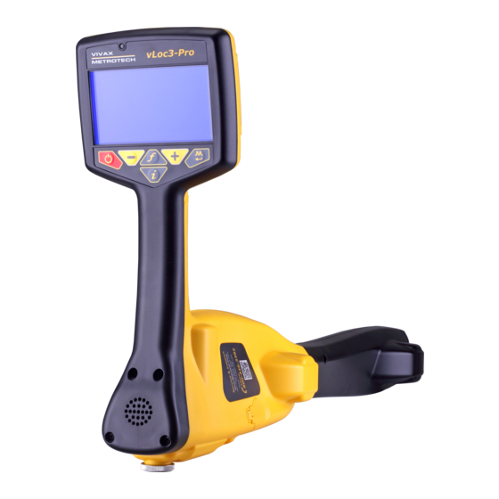
These receivers will be referred to as vLoc3 series, vLoc3 receiver, receiver, or locator. The vLoc3 Series Receivers are precision locators designed to meet the needs of utility companies and their contractors. The following describes the features and use of the receiver. -
Page 10: Charging The Receiver Batteries
Series Receivers Charging the Receiver Batteries The vLoc3 series receivers can be used with the alkaline or the custom Li-ion rechargeable battery pack. The central illuminated section within the battery icon indicates the amount of charge remaining. • Blue centre indicates alkaline batteries. -
Page 11: The Vloc3 Series Keypad
Long press = enter the menu The vLoc3 Series User Menu The user-configurable vLoc3 series receivers can be customized to suit the user’s preferences. The receivers have several features that can be switched on and off through the user menu. -
Page 12: Setup - Operational
Series Receivers Backlight – Press the Enter key to change the backlight intensity to Low, Medium, High, or Auto. The use of the “Auto” selection is recommended because the receiver has a built-in light sensor that automatically adjusts the backlight intensity to the surrounding lighting conditions. -
Page 13: Setup - Feature
– The Loc3 series transmitters can be remotely operated from the receiver. This option requires the Transmitter (radio) Link to be installed in both the vLoc3 series receiver and the Loc3 series transmitter. Tx-Link is a factory fit option that must be purchased at the time of ordering. Currently, the Tx-Link feature is only available in the Loc3 series 5-watt and 10-watt transmitters. -
Page 14: Warnings And Alerts
Series Receivers Warnings and Alerts Warning symbols accompanied by an audible sound and vibration in the handle unless configured otherwise in the MyLocator3 desktop app. Warnings can also be switched off in the setup menu. 61.4 24dB SD-EUR 2.6.1... -
Page 15: Vloc3 Series Locate Modes And Screens
Series Locate Modes and Screens Note - The vLoc3 series user interface is under continual development. The screenshots described here may differ slightly from your screens. The vLoc3 series receivers give the user a choice of locating screens. -
Page 16: The Classic Screen Status Bar
Series Receivers 2.7.1 The Classic Screen Status Bar All vLoc3 series screens have a status bar at the top indicating various locator settings. 18.3 0.39m The vLoc3 Series Status Bar Bluetooth status (If Transmitter link is fitted this icon... -
Page 17: Classic Locating Modes (Response)
Series Receivers Classic Locating Modes (Response) The vLoc3 series receivers have an array of six antennas, and these can be toggled through different configurations (modes) to provide different responses to the signals radiating from buried utilities. The modes are: 2.8.1... -
Page 18: Peak With Arrows Mode
Series Receivers 2.8.5 Peak with Arrows Mode The Peak with Arrows mode operates in the same way as the peak mode. It gives the largest meter deflection when directly over the line. However, the left/right indication arrows are also displayed. -
Page 19: Alternative Locate Screens
Alternative Locate Screens As previously mentioned, the vLoc3 series receivers have alternative locate screens. The following section describes the operation of these screens. It is left to the user to decide which is the best screen for a particular application. -
Page 20: The Transverse Plot Screen
Series Receivers The color of the confidence circle also changes depending on the degree of confidence: Green - Low distortion/high confidence. Blue - Minor distortion/medium confidence, so please proceed with care. Red - Excessive distortion/low confidence. Treat all data and measurements with caution. - Page 21 Series Receivers Depth and current readings Frequency selected Target line Lines of confidence (the closer these are to the target line indicates more confidence) The Arrow indicates the direction to move toward the line. It only shows when the distance to the target line is far away...
-
Page 22: Using The Vloc3 Series Receivers
Using the vLoc3 Series Receivers 3. Using the vLoc3 Series Receivers Passive Locating NOTE The compass indicator is not active during the passive location. Passive locating refers to the process of detecting signals that naturally occur on pipes and cables. These tend to fall into two categories, radio signals and power signals. -
Page 23: Detecting Radio Signals
Using the vLoc3 Series Receivers NOTE Note that there will be no sound from the speaker until the meter reading is above approximately 10% of the full scale. Keeping the vLoc3 receiver vertical, walk across the area to be checked keeping the orientation so that the blade is in line with the direction of walking, see the above diagram. -
Page 24: Active Locating: Applying The Transmitter
Using the vLoc3 Series Receivers Active Locating: Applying the Transmitter Active locating uses a transmitter to apply a precise frequency to a pipe or cable then uses a receiver turned to detect the signal being radiated at that precise frequency. Active location frequencies can be applied by direct connection, signal clamp, or induction (this is further explained in the following sections). -
Page 25: Signal Clamp (For Frequencies Above 8Khz)
Using the vLoc3 Series Receivers To make a direct connection, insert the direct connection connector to the transmitter. Insert the ground stake into the ground a few meters perpendicular to the line. Connect the black lead to the ground stake. Next take the red lead and connect to the target line. -
Page 26: Induction (For Frequencies Above 8Khz)
Using the vLoc3 Series Receivers When applying a clamp close to a grounding point where multiple grounds or a grounding bus exists ensure that you place the clamp around the target line and not to the ground bus/other grounds. This will help focus the applied signal on the target line. -
Page 27: Locating Active Signals
Using the vLoc3 Series Receivers Remove all connections from the output connector. Switch on the transmitter and place it over the suspected position of the line and position it so that it is in line with the target. In the case of the Loc3 series transmitters that will be with the handle pointing along the line. - Page 28 Using the vLoc3 Series Receivers 69.1 25dB 640Hz Hold the locator vertically and rotate it on its axis until the compass indicates Forward/Back, as shown above. Adjust the sensitivity control so that the display indicates approximately 50%. Keeping the vLoc3 receiver vertical move to the side slightly.
-
Page 29: Searching (Sweeping) An Area In The Peak Mode
Using the vLoc3 Series Receivers Searching (sweeping) an Area in the Peak Mode Buried utilities may be parallel to each other and frequently they cross the area being searched at various angles and depths. As the locator antennas response is directional (using the traditional screen), it is important to search the area in the same or similar pattern as shown. -
Page 30: Distorted Fields
The Vector screen has a circle drawn around the target line, which increases in size in the presence of possible distortion. The Plan view screen has “Tram” lines on either side of the calculated position, which moves further from the line as possible distortion is detected. -
Page 31: Sonde Location Mode
Using the vLoc3 Series Receivers Sonde Location Mode A Sonde is typically used for locating non-metallic pipes or ducts or the camera end of a sewer inspection camera. Low- frequency versions (512Hz/640Hz) can transmit through some metallic pipes such as cast iron pipes which is why they are frequently used with sewer inspection cameras. -
Page 32: Signal Direction Precision Identification Mode
SD option installed will show this SD icon label on the receiver's blade where it meets the yellow upper housing. Some vLoc3 series of locators contain a feature called Signal Direction or SD. This feature verifies that the line being located is the same line that the transmitter is connected to. - Page 33 Using the vLoc3 Series Receivers As a result multiple signals radiate from cables and pipes in the area making it difficult to identify the target line. These return signals are typically traveling in the opposite direction than the applied signal. The Signal Direction feature identifies which direction the signal is flowing and hence the target line.
- Page 34 Using the vLoc3 Series Receivers 62.6 25dB SD-USA • Re-trace your line back to a point where a solid signal direction is obtained. Precisely pinpoint the line and stand with your back to the direction of the transmitter as you did when you initiated the original sync and press the “i” pushbutton, then the enter/return pushbutton to re-sync with the transmitter signal.
-
Page 35: Vloc3-Ml Receiver
vLoc3-ML Receiver 4. vLoc3-ML Receiver The vLoc3-ML Locator and vLoc3-MLA Locator Adapter accessory both detect the presence of buried EMS markers. The Marker Modes and Locate Screens are identical. Serial Number and Software Revisions Always quote your receiver and accessory model number, serial number, and software revision number when requesting product support. -
Page 36: Vloc3-Ml Receiver
The operation of the vLoc3-ML and vLoc3-MLA are exactly the same with the exception of Depth Measurement. Depth measurement with the vLoc3-MLA is covered in section 4.4.1.1 of this manual. When not being used as a standard cable locator, the vLoc3 series receivers can be operated in two other configurations: • Dedicated marker locator •... - Page 37 vLoc3-ML Receiver Either use the pushbutton to select the marker type that is to be located or use a long press on the button to enter the user menu. Select the "Marker Type" which will then cause the display to show the complete range of markers available together with their operating frequencies.
-
Page 38: Dual Configuration
Use the locator to identify the position of the cable or pipe. Trace the line using the same technique as a standard vLoc3 series locator. The bar graph indicates the signal strength from the cable. The bar graph is always colored blue in the Dual configuration mode and does not indicate signal distortion or marker type. -
Page 39: Vloc3-Mla
Set-up the vLoc3-MLA Attaching the vLoc3-MLA Accessory Take the vLoc3-MLA accessory and push-fit it onto the end of the vLoc3 series receiver blade. Ensure it clicks to lock into place. Now take the 8-pin ninety-degree connector and plug it into the accessory socket on the vLoc3 receiver. -
Page 40: Operation Of The Vloc3-Mla
vLoc3-ML Receiver Push the provided cable retainer over the blade and cable so that the cable is secured. Removing the vLoc3-MLA Accessory To remove the MLA accessory first remove the cable retainer by pulling it over the vLoc3 receiver blade. Then unplug the accessory from the vLoc3 receiver accessory socket To remove the accessory it is necessary to simultaneously push the two yellow retaining buttons positioned on both sides of the accessory. - Page 41 vLoc3-ML Receiver Press the button. The screen will change to a similar screen as the illustration shown on the right. Marker Locator Adapter When prompted (when the animation starts) lift the receiver straight up eight inches/20cm. Marker Locator Adapter 20cm Raise the locator eight inches/20cm and press the button as indicated by the animation.
-
Page 42: Data Logging
Data Logging 5. Data Logging The vLoc3 series receivers have four gigabytes of internal memory that can be used to store locator data. Four gigabytes of space can save many thousands of records. The records are user-initiated and stored by the user whenever the “+” button is pressed when in the “Information” screen. -
Page 43: Bluetooth
After the deletions are complete, the vLoc3 will return to the locate/ accessory screen. Bluetooth As an option the vLoc3 series receivers can be upgraded by the user with a Bluetooth module to communicate with external GPS modules or Dataloggers. vLoc3 Series Bluetooth Module ™... -
Page 44: Fitting The Bluetooth Module
Bluetooth pairing with external devices. Switch on the external device. Switch on the vLoc3 series receivers and enter the user setup menu by a long press on the “i ” button. Use the “+” and “-” keys to scroll to and select Bluetooth Pairing. -
Page 45: Transferring Data From The Vloc3 Receiver To A Computer
Follow the instructions to download and install the application. A “MyLocator3” icon will appear on the computer desktop after the app is installed. Connect your vLoc3 series receivers to the computer via the mini-USB connector which can be found under the battery cover flap. Launch MyLocator3 by double clicking on the icon. -
Page 46: Application Update
Data Logging The MyLocator3 startpage MyLocator3 can be viewed in several language options. Click on the pull-down menu to select the desired option. 5.3.2.2 Application Update Every time the MyLocator3 Application is started, its version number is checked against the latest version available on the Vivax- Metrotech server. -
Page 47: Toolbar
Toolbar The vLoc3 series receivers can be configured so that features can be switched on or off. Doing this enables the user to tailor the instrument to meet their application's needs while keeping the user interface uncluttered. The toolbar at the top of the screen enables the user to create configurations. -
Page 48: Splash Screen
Data Logging Data Log management screen Before exporting the data use the Log Type dropdown tab to select the type of data required. Options are: Log Type dropdown list 5.3.5 Splash Screen In this section, an image can be loaded as a splash screen when the locator is turned on. The locator has an LCD screen with a resolution of 480 by 272 pixels. - Page 49 Data Logging The Splashscreen download area To remove a startup screen and revert to the default Vivax-Metrotech screen, click on the “Clear” button and download the cleared screen. The default factory loaded splash screen ™ Page 43 of 59...
-
Page 50: Frequencies Page
Data Logging 5.3.6 Frequencies Page The “Frequencies” page allows the user to select which frequencies and modes are available when the locator's F-key is pressed and which frequencies appear on the locator's menu. The Frequency page list 5.3.7 Menu Settings The “Menu Settings”... -
Page 51: Advanced Features
Data Logging 5.3.8 Advanced Features The Advanced Features are available to those users in possession of a USB security dongle. If a dongle is attached to the PC, its level will be displayed on the MyLocator3 status bar. Three levels of security come with the dongle. Level one is for the end-user supervisors, level two for Vivax-Metrotech's distributors, repair centers, managers, and level three for Vivax-Metrotech use only. -
Page 52: The Loc3 Series Transmitters
Using the Accessories 6. The Loc3 Series Transmitters This section of the manual covers the 5-watt, 10-watt and 25-watt Transmitters. Loc3 Series Transmitter Overview The Loc3 series transmitters are rugged portable transmitters powered by Li-ion rechargeable li-ion batteries or alkaline “D” cells. 5 and 10-Watt Transmitters Loc3 series transmitter Ground stake... -
Page 53: Pushbuttons
Using the Accessories 25-Watt Transmitter Display High Voltage Warning* Active frequency 4 Hz/98 Hz Mode indication icon 3 9 0 Units (mA, volts, ohms) Speaker level Output step bar graph Battery level or DC Input icon Digital readout (mA, volts, ohms) *Output Protect Warning The transmitter checks the line when connected. -
Page 54: Transmitter Connections Block
Using the Accessories 25-Watt Transmitter Menu Structure About Frequency Menu Receiver Link Disabled LCD Contrast Resistance Voltage Volume When the “i ” pushbutton is pressed the display will show the volume level. Use the + and - pushbuttons to increase, reduce or turn the speaker off. -
Page 55: Charging The Transmitter Battery Tray
Using the Accessories NOTE The 25-watt transmitter ships with the Li-ion battery tray. An optional alkaline tray can be used with the 25-watt transmitter but the power output will be limited to 10-watts. WARNING Use only Vivax-Metrotech recommended charger. Do not attempt to replace the rechargeable batteries or remove battery covers. Return to Vivax-Metrotech or a Vivax-Metrotech approved service center for replacement. -
Page 56: Removing And Installing The Battery Tray
Using the Accessories Removing and Installing the Battery Tray These procedures apply to both the Alkaline and Rechargeable battery tray. Removing the battery tray 1. Reach under the catch and pull 2. Lift up the catch and repeat for 3. Lift the transmitter base from the to unlock. -
Page 57: Direct Connection Mode
Using the Accessories 6.7.1 Direct Connection Mode The Direct Connection mode is automatically selected by plugging a connection lead into the output socket. An icon confirming the direct connection mode is shown on the display. The wave in the icon fluctuates when the transmitter is operating. The direct connection lead consists of two colored cables with clips and covers. -
Page 58: Induction Mode - 5 And 10-Watt Transmitters Only
Using the Accessories 6.7.3 Induction Mode – 5 and 10-Watt Transmitters Only The 5 and 10-watt transmitters use an internal antenna to induce a locating frequency onto the target utility. The Induction mode is automatically selected if no connection accessories are plugged into the “output socket.” An icon indicating the “Induction” mode will show on the display. -
Page 59: Most Used Frequencies (Frequency Selection) Feature
Using the Accessories 25-Watt Transmitter Frequencies power outputs Loc3-25Tx Direct connection 25-watt: 32Hz - 9.82kHz 128Hz 512Hz 8.19kHz 4Hz/8Hz/128Hz 4Hz/8Hz/512Hz 4Hz/8Hz/128Hz 3Hz/128Hz Pushbutton Pushbutton 4Hz/128Hz As with most manufacturers, signal clamps are tuned to specific frequencies and will not work over the complete range of frequencies. -
Page 60: Multi-Frequency Mode For Direct Connection
Using the Accessories About Frequency Menu Receiver Link Disabled About LCD Contrast Frequency Menu Resistance Receiver Link Disabled In SD mode Voltage LCD Contrast Volume Volume 5 and 10-Watt Transmitters 25-Watt Transmitter About Frequency Menu About Receiver Link Disabled Frequency Menu LCD Contrast Receiver Link Disabled LCD Contrast... -
Page 61: Transmitter Link (Tx-Link)
The Loc3 series transmitters can be remotely operated from the receiver. This option requires the Transmitter (radio) Link to be installed in both the vLoc3 series receiver and the Loc3 series transmitter. Tx-Link is a factory fit option that must be purchased at the time of ordering. The radio link range depends on having a clear “line of sight”... - Page 62 While the icon on the transmitter is flashing, indicating that it is waiting Transmitter Link to connect to a receiver, switch on the vLoc3 series receiver and enter Transmitter Control the user menu by pressing and holding the information button. Scroll down the menu options until Transmitter Link is highlighted.
- Page 63 Using the Accessories Menu Imperial/Metric Meter Continuous Information Depth & current From the main menu, select the “Transmitter Control” option. (that will Auto Power Off Never become visible when the two devices are linked) Warnings A screen similar to the below should be seen: Bluetooth Pairing Transmitter Link Transmitter Control...
-
Page 64: Locator Accessories
Locator Accessories 7. Locator Accessories Transmitter Signal Clamps Clamps are accessories used to apply the transmitter signal to an insulated line, removing the need to connect the transmitter signal directly to a conductor or cable sheath. Clamps are available in 2-inch (50mm), 4-inch (100mm) and 5-inch sizes. An 18-inch (45cm) flexible version is also available. A-Frame Fault Locator The A-frame accessory is used to detect ground faults on pipes and cables. -
Page 65: Glossary
Glossary 8. Glossary Active Locate A locate where a transmitter is used to apply a signal to a buried pipe or cable, the position of which is then located by a receiver tuned to the same frequency. Active Signal A signal is applied by the locator transmitter to a buried line. Typical, this is a very precise frequency. - Page 66 Notes: Vivax-Metrotech Corporation 3251 Olcott Street, Santa Clara, CA 95054, USA Toll-Free: 1-800-446-3392 Phone: +1 (408) 734-1400 Website: www.vivax-metrotech.com ™...
Need help?
Do you have a question about the vLoc3 Series and is the answer not in the manual?
Questions and answers