Vivax Metrotech vLoc3 RTK-Pro User Handbook Manual
Hide thumbs
Also See for vLoc3 RTK-Pro:
- User handbook manual (78 pages) ,
- Quick setup manual (28 pages) ,
- Quick setup manual (36 pages)
Table of Contents
Advertisement
Quick Links
Advertisement
Table of Contents

Subscribe to Our Youtube Channel
Related Manuals for Vivax Metrotech vLoc3 RTK-Pro


Summary of Contents for Vivax Metrotech vLoc3 RTK-Pro
- Page 1 RTK-Pro User Handbook (English Edition) Version 1.1 P/N: 4.04.000170...
- Page 3 General Safety & Care Information Who Can Use This Equipment • This equipment must only be used by people suitably trained in the use of pipe and cable locators. Work-site Safety • Use your company’s or other applicable safety codes and rules when using this equipment. •...
- Page 4 Care of Equipment • Use equipment only as directed in this User Handbook. • Do not immerse any part of this equipment in water. • Store in a dry place. • Keep equipment in the case provided when not in use. •...
-
Page 5: Table Of Contents
Self-Test ..................................8 Warnings and Alerts ................................9 2.6.1 Warnings and Alerts Descriptions ........................9 2.6.2 DFT (Discrete Fourier Transform) ........................9 Setting up the vLoc3 RTK-Pro mapping functions......................10 2.7.1 SIM Set-up ................................11 2.7.2 Set up the RTK connections using MyLocator3 ....................12 2.7.3 Set up the RTK settings in the Locator......................13 2.7.4... - Page 6 Locating Active Signals ..............................30 Searching (sweeping) an Area in the Peak Mode ......................31 Searching (sweeping) an Area in the Omni Peak Mode ....................31 Tracing a Buried Line ..............................31 Depth & Current Measurement .............................31 Distorted Fields ................................32 Sonde Location Mode ..............................33 3.10 Walk Back Feature ................................35 3.10.1 VMMap Web Portal ............................35...
- Page 7 5.8.3 Multi-Frequency Mode for Direct Connection ....................60 Transmitter Link (TX-Link) ..........................61 6. Accessories & Options ................................64 Transmitter Signal Clamps ............................64 A-Frame Fault Locator ..............................64 vLoc3-MLA (Marker Locator Adapter) ...........................64 7. Glossary ....................................65 ™...
-
Page 9: Service & Support
Service & Support 1. Service & Support Serial Number and Software Revision Number Always quote your receiver and transmitter model number, serial number, and software revision number when requesting product support. They can be found as follows: (for reference only). Model &... -
Page 10: Service Centers Closest To You
Service & Support Service Centers Closest to You: Worldwide Sales Offices and Service Centers World Headquarters, United States of America Central/South America and the Caribbean Vivax-Metrotech Corporation Ventas para América Latina 3251 Olcott Street, Santa Clara, CA 95054, USA 3251 Olcott Street, Santa Clara, CA 95054, USA T/Free : 1-800-446-3392 T/Free... -
Page 11: Vloc3 Rtk-Pro Receiver
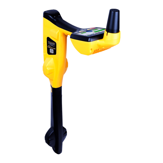
The vLoc3 RTK-Pro is a Precision Location System designed to meet utility companies and their contractors' needs. The following describes the features and use of the receiver. This user manual covers the vLoc3 RTK-Pro receiver. In this manual, this receiver may be referred to as vLoc3 series receiver, receiver or locator. -
Page 12: Charging The Receiver Batteries
RTK-Pro Receiver Charging the Receiver Batteries The RTK-Pro can be used with either alkaline batteries or an interchangeable rechargeable battery pack. The central illuminated section within the battery icon indicates the amount of charge remaining. • Blue center indicates alkaline batteries. -
Page 13: Vloc3 Rtk-Pro Receiver Keypad
RTK-Pro Receiver vLoc3 RTK-Pro Receiver Keypad The grey color keys (3, 5, and 6) serve dual functions. You may have to Short Press by momentarily pressing the key or Long Press by pressing and holding the key until the desired function is shown. -
Page 14: Setup - Receiver
RTK-Pro Receiver Menu Menu About Language English Speaker Volume Imperial / Metric Meter Sound Configuration Continuous Information Backlight Auto Auto Power Off Never Frequency Warnings Classic Locate GPS Source Internal Satellite Information Locate Perspective Menu Transmitter Link Transmitter Control... -
Page 15: Setup - Feature
Vector Locate Transverse Graph Plan View Sonde GPS Source - Press the “Enter” key to select either Internal or Bluetooth. For the vLoc3 RTK-Pro, this is typically set to internal. 2.4.3 Setup - Feature Warnings – Warnings relating to - Shallow cable, Overload, Overhead cable, and Signal Overload. Scroll down to the relevant warning and use the return button to select or de-select. -
Page 16: Setup - Informational
RTK-Pro Receiver Transmitter Control – This feature is used to control a transmitter with the Radio Link activated remotely. For more information, see the section “Remote Operation of the transmitter.” – Discrete Fourier Transform is a tool to help choose a frequency to apply to the target conductor. The DFT feature will aid the user with nearby interference that may affect the locate quality. -
Page 17: Warnings And Alerts
RTK-Pro Receiver Warnings and Alerts Warning symbols are accompanied by an audible sound and vibration in the handle unless otherwise configured in the MyLocator3 desktop app. Warnings can also be switched off in the setup menu. 61.4 24dB 32.8kHz 2.6.1... -
Page 18: Setting Up The Vloc3 Rtk-Pro Mapping Functions
Introduction This section describes the set-up and operation of the vLoc3 RTK-Pro in terms of the GNSS mapping capabilities. The equipment is designed to provide cm accuracy. However, on its own, GNSS is not capable of providing the cm accuracy required for many survey applications. -
Page 19: Sim Set-Up
RTK-Pro Receiver Satellite Satellite Internet (Cloud) Satellite Satellite Cellular Tower Trip caster vLoc3 RTK-Pro Base 1 Base 2 Base 3 This set-up procedure assumes the operator has a suitable data-enabled SIM card registered with a cellular network provider and that the operator has registered with an RTK provider. -
Page 20: Set Up The Rtk Connections Using Mylocator3
RTK-Pro Receiver 2.7.2 Set up the RTK connections using MyLocator3 Download and install the MyLocator3 desktop app. The app can be downloaded from the Vivax-Metrotech website under Products > Apps. Connect the locator to the computer running the MyLocator3 app with the provided mini-USB cable. -
Page 21: Set Up The Rtk Settings In The Locator
RTK-Pro Receiver 2.7.3 Set up the RTK settings in the Locator It should now be possible to start using the locator, but first, a few locator settings need to be set. About GPS Module ZED-F9P GPS Version HPG 1.12... -
Page 22: Set The Vmmap Cloud Settings
RTK-Pro Receiver Every 30 seconds the “RTCM status” will show “Sending GGA” as the vLoc3-RTK sends its GPS position to the NTRIP caster in an NMEA0183 GGA message if applicable “RTCM count” shows an incrementing count of RTCM packets successfully received... - Page 23 RTK-Pro Receiver Cloud When there are logs to send to the Cloud, the “Cloud Status” will show: Cloud Status Requesting Authentication “Connecting,” “Requesting Region Server,” “Region Server Received” The RTK-Pro uses its serial number to understand which regional VXMT VMMAP Cloud server it should connect to.
-
Page 24: Rtk-Pro Battery Consumption
Alternatively, a spare receiver battery can be purchased. vLoc3 RTK-Pro Locate Modes and Screens Note - The vLoc3 series user interface is under continual development. The screenshots described here may differ slightly from your screens. -
Page 25: The Classic Screen
2.10 Classic Locating Modes (Response) The vLoc3 RTK-Pro receiver has an array of six antennas, and these can be toggled through different configurations (modes) to provide different responses to the signals radiating from buried utilities. The modes are: 2.10.1 Peak Response Mode Two horizontal antennas provide a “Peak”... -
Page 26: Broad Peak Mode
RTK-Pro Receiver 2.10.2 Broad Peak Mode A single horizontal antenna provides a “Peak” or maximum signal response over the buried line. The result is a less defined peak than the twin horizontal antenna “Peak” mode. This mode is useful in deep lines because using a single antenna can boost the received signal. -
Page 27: Omni Peak Response Mode
RTK-Pro Receiver 2.10.6 Omni Peak Response Mode The two double-ended arrows around an icon mean that the line is detectable regardless of locator blade orientation. It is very useful for quickly checking an area for buried lines using a grid search as one sweep will catch all locatable lines. -
Page 28: Alternative Locate Screens
2.11 Alternative Locate Screens As previously mentioned, vLoc3 RTK-Pro has several alternative screens. The following section describes the operation of these screens. It is left to the user to decide which is the best screen for a particular application. To scroll through the available screens, use long key presses on the “return” key. -
Page 29: The Transverse Graph Screen
RTK-Pro Receiver 1.43m 1.86m The color of the confidence circle also changes depending on the degree of confidence: Green - Low distortion/high confidence. Blue - Minor distortion/medium confidence, so please proceed with care. Red - Excessive distortion/low confidence. Treat all data and measurements with caution. -
Page 30: The Plan View Screen
RTK-Pro Receiver 2.11.3 The Plan View Screen The plan view screen shows a picture as if you were viewing the line from above ground. When the red line is in the center and pointing forward/backward, you are directly over the line and pointing in the line's direction. - Page 31 RTK-Pro Receiver As long as the locator is detecting a valid signal, the depth (or current) will be available regardless of locator orientation, i.e., the locator does not need to be aligned with the target line in the forward back orientation. It is recommended that, in this mode, the current is always displayed as the signal may bleed off onto other services.
-
Page 32: Using The Vloc3 Rtk-Pro
Detecting Power Signals Switch on the vLoc3 RTK-Pro receiver and select Power mode using the “f” button. Notice that the antenna mode indicator will be showing “Peak” or “Omni peak,” as these are the only options in the passive modes. -
Page 33: Detecting Radio Signals
Keeping the vLoc3 RTK-Pro vertical, walk across the area to be checked, keeping the orientation so that the blade is in line with the direction of walking (See diagram above). If using the Onmi Peak mode, the orientation of the locator is not important. -
Page 34: Active Locating:- Applying The Transmitter
Using the vLoc3 RTK-Pro Active Locating:- Applying the Transmitter Active locating uses a transmitter to apply a precise frequency to a pipe or cable, then uses a receiver turned to detect the signal being radiated at that precise frequency. Active location frequencies can be applied by direct connection, signal clamp, or induction (This is further explained in the following sections). -
Page 35: Transmitter Signal Clamp (For Frequencies Above 8Khz)
Using the vLoc3 RTK-Pro To make a direct connection, insert the direct connection connector to the transmitter. Insert the ground stake into the ground a few meters perpendicular to the line. Connect the black lead to the ground stake. Now take the red lead and connect to the target line. - Page 36 Using the vLoc3 RTK-Pro When applying a clamp close to a grounding point where multiple grounds or a grounding bus exists, ensure that you place the clamp around the target line and not to the ground bus/other grounds. This will help focus the applied signal on the target line.
-
Page 37: Induction (For Frequencies Above 8Khz)
Using the vLoc3 RTK-Pro 3.2.3 Induction (for frequencies above 8kHz) When no direct connection lead or signal clamp is connected, the transmitter will automatically start to radiate (induce) a signal around the transmitter. These signals will penetrate the ground and couple onto buried lines. The signal will then travel along the line, which can be detected with the vLoc3 receiver. -
Page 38: Locating Active Signals
Using the vLoc3 RTK-Pro Locating Active Signals These instructions assume that the Classic Screen is selected, and Peak with Arrows mode is selected for the antenna configuration. With a transmitter, apply an active locate signal to the line. Set the receiver to Peak with Arrows Match the frequency of the receiver to that of the transmitter. -
Page 39: Searching (Sweeping) An Area In The Peak Mode
Using the vLoc3 RTK-Pro Searching (sweeping) an Area in the Peak Mode Buried utilities are not parallel to each other, and frequently they cross the area being searched at various angles and depths. As locator antennas' response is directional (using the traditional screen), it is important to search the area in the same or similar pattern as shown. -
Page 40: Distorted Fields
Using the vLoc3 RTK-Pro If the Omni mode is selected, the locator's orientation is not important, but it is still necessary to pinpoint the line accurately before taking a depth measurement. The signal current value will also be displayed. This feature is useful for confirming that the detected signal is radiating from the correct line. -
Page 41: Sonde Location Mode
Using the vLoc3 RTK-Pro • Measure the buried line's depth by pressing the “i” pushbutton briefly to measure depth and current. The depth should be approximately in line with the “as-built” plans available. If no plans are available, logic would still help assess the situation (for instance, if you are looking for a shallow CCTV distribution cable and the depth indicated is 5-feet (1.5m), it should raise a... - Page 42 Using the vLoc3 RTK-Pro The vLoc3 Sonde Screen will display the Large Peak as a Sonde icon and the Null Points as double blue circles, as shown in the illustration to the right. Method Switch on the vLoc3 receiver and use long presses on the Enter key to enter the Sonde screen.
-
Page 43: Walk Back Feature
Using the vLoc3 RTK-Pro 11. Note that it may be necessary to confirm the Sonde position when directly over the Sonde, left to right. Do this by moving the locator left to right to identify the strongest signal's position, as indicated on the bar graph. At this time, the depth of the Sonde will be displayed at the top of the display. - Page 44 Using the vLoc3 RTK-Pro Once the desired points are selected an automatic description is assigned. These descriptions can be edited if so desired. When all the needed points are selected click on the "Add" option on the bottom left. A pop-up window will appear with the option of a drop-down with available RTK-Pro serial numbers. Select one or more serial numbers of receivers that would need the Walk Back points assigned.
-
Page 45: Performing An Rtk-Pro Walk Back
Using the vLoc3 RTK-Pro 3.10.2 Performing an RTK-Pro Walk Back Now that the Walk Back points have been selected, the VMMap cloud uses the RTK-Pro receiver containing the assigned receiver serial number and Walk Back points. In the RTK-Pro menu, navigate to scroll to Walk Back and enter the sub-menu option. - Page 46 Using the vLoc3 RTK-Pro 50°57′32.1586′′N 564′2′′ Follow the guidance arrow to get near the Walk Back point. Once within 10-feet 3°52′29.1374′′W 0′1′′ (2DRMS) (3m), a crosshair icon will be displayed. A spirit level is shown. The center of the spirit level represents the location of the GNSS antenna. You must maintain the locator's orientation and move forwards and backward, left and right, and not 9′5′′...
-
Page 47: Feature Logging
Using the vLoc3 RTK-Pro *Please note some screens and images have been simulated and do not represent the final product. 3.11 Feature Logging Feature Logging is for collecting additional information on an underground utility or its surrounding above-ground point of interest. -
Page 48: Logging Features
Using the vLoc3 RTK-Pro 11. In the Feature Logging sub-menu, select the “Open” to select the .xlsx file created in the previous steps. 12. Once the file has been selected a review of the containing features will be displayed by pressing the small triangle next to “Feature Definitions.”... -
Page 49: Auto Log Feature
Using the vLoc3 RTK-Pro 50°57′32.1396′′N 564′2′′ 50°57′32.1396′′N 564′2′′ 3°52′29.1374′′W 1′7′′ (2DRMS) 3°52′29.1374′′W 1′7′′ (2DRMS) Spirit Level is displayed Aligned GNSS Antenna 3.11.4 Auto Log Feature To enable the Auto Log Function, navigate to the main menu and find “Auto Log Feature.” Two options are presented to the user Enabled or Disabled. -
Page 50: Feature Logs In Vmmap Cloud
Using the vLoc3 RTK-Pro 3.11.5 Feature Logs in VMMap Cloud Once feature logs are synced with the utility survey in the cloud, a unique pin is assigned. The example below shows the location pin is brown; it also contains an “F”... -
Page 51: Data Logging
Data Logging 4. Data Logging The RTK-Pro has an internal memory to store locator data. (Or if activated, can be sent to the “cloud”) The available storage size is four gigabytes, which relates to many thousands of records. The user records the records whenever the “+” button is pressed while in the “Information” screen. Data can be stored relating to a standard locate or relating to any of the receiver accessories. -
Page 52: Pairing The Receiver With Dataloggers, Mobile Phones And Other External Devices
Bluetooth pairing with external devices. Switch on the external device. Switch on the vLoc3 RTK-Pro and enter the User setup menu by a long press on the “i” button. Use the “+” and “-” keys to scroll to and select the “Bluetooth Pairing” option. -
Page 53: The Mylocator3 Desktop App
Data Logging To transfer the locator's data logs, use the RTK-Pro configurator tool, Mylocator3. This desktop application can be downloaded from the Vivax-Metrotech website at www.vivax-metrotech.com in the apps section. To view Google Earth .kml files the Google Earth app is needed. This free app can be found by doing a google search for “Google Earth.”... -
Page 54: Application Update
Data Logging 4.3.2.2 Application Update Every time the MyLocator3 Application is started, its version number is checked against the latest version available on the Vivax-Metrotech server. The user is notified if an update is available, as shown below. This feature will only be available if the computer is “online.”... -
Page 55: Toolbar
Data Logging 4.3.3 Toolbar The RTK-Pro locator can be configured so that features can be switched on or off. Having this option enables the user to tailor the instrument to meet their needs and keep the user interface uncluttered. The toolbar at the top of the screen enables the user to create configurations. -
Page 56: Splash Screen
Data Logging Data Log management screen Before exporting the data, use the “Log Type” dropdown tab to select the type of data required. Options are: Log Type dropdown list 4.3.6 Splash Screen This option loads an image to be used as a splash screen when the locator is turned on. The locator has an LCD screen with a resolution of 480 by 272 pixels. - Page 57 Data Logging The Splash Screen download area To create your startup screen, first, click on the “Open” button. Now browse your files to select the picture to use as the start-up screen. The compatible file formats are .jpg, .bmp, .png, and .gif. The start-up screen will be displayed in the application.
-
Page 58: Frequencies Page
Data Logging 4.3.7 Frequencies Page The “Frequencies” page allows the user to select which frequencies and modes are available when the locator's F-key is pressed and which frequencies appear on the locator's menu. The Frequency page list 4.3.8 Menu Settings The “Menu Settings”... -
Page 59: Cloud, Internet And Rtk Settings
Data Logging 4.3.9 Cloud, Internet and RTK Settings Click on the Cloud/Internet icon, which allows you to set the cloud settings. A Screen similar to the below will be shown: “Network” “apn:” should be adjusted to the Access Point Name for your chosen Mobile network – be sure not to add any spaces before or after the APN. -
Page 60: The Loc3 Series Transmitters
The Loc3 Series Transmitters 5. The Loc3 Series Transmitters This section of the manual covers the 5-watt, 10-watt and 25-watt Transmitter. Loc3 Series Transmitter Overview The Loc3 series transmitters are rugged portable transmitters powered by Li-ion rechargeable li-ion batteries or alkaline “D” cells. 5 and 10-Watt Transmitters Loc3 series transmitter Ground stake... -
Page 61: Pushbuttons
The Loc3 Series Transmitters 25-Watt Transmitter Display High Voltage Warning* Active frequency 4 Hz/98 Hz Mode indication icon 3 9 0 Units (mA, volts, ohms) Speaker level Output step bar graph Battery level or DC Input icon Digital readout (mA, volts, ohms) *Output Protect Warning The transmitter checks the line when connected. -
Page 62: Transmitter Connections Block
The Loc3 Series Transmitters 25-Watt Transmitter Menu Structure About Frequency Menu Receiver Link Disabled LCD Contrast Resistance Voltage Volume When the “i” (information) pushbutton is pressed, the display will show the volume level. Use the + and - pushbuttons to increase, reduce or turn the speaker off. -
Page 63: Charging The Transmitter Battery Tray
The Loc3 Series Transmitters NOTE The 25-watt transmitter ships with the Li-ion battery tray. An optional alkaline tray can be used with the 25-watt transmitter, but the power output will be limited to 10-watts. WARNING Use only Vivax-Metrotech recommended charger. Do not attempt to replace the rechargeable batteries or remove battery covers. -
Page 64: Removing And Installing The Battery Tray
The Loc3 Series Transmitters Removing and Installing the Battery Tray These procedures apply to both the Alkaline or Rechargeable battery tray. Removing the battery tray 1. Reach under the catch and pull to 2. Lift the catch and repeat for all 3. -
Page 65: Direct Connection Mode
The Loc3 Series Transmitters 5.7.1 Direct Connection Mode The Direct Connection mode is automatically selected by plugging a connection lead into the output socket. An icon confirming the direct connection mode is shown on the display. The wave in the icon fluctuates when the transmitter is operating. The direct connection lead consists of two colored cables with clips and covers. -
Page 66: Induction Mode - 5-Watt And 10-Watt Transmitters Only
The Loc3 Series Transmitters 5.7.3 Induction Mode – 5-Watt and 10-Watt Transmitters Only The 5-watt and 10-watt transmitters use an internal antenna to induce a locating frequency onto the target utility. The Induction mode is automatically selected if no connection accessories are plugged into the “output socket.” An icon indicating the “Induction” mode will show on the display. -
Page 67: Most Used Frequencies (Frequency Selection) Feature
The Loc3 Series Transmitters 25-Watt Transmitter Frequencies power outputs Loc3-25Tx Direct connection 25-watt: 32Hz - 9.82kHz 128Hz 512Hz 8.19kHz 4Hz/8Hz/128Hz 4Hz/8Hz/512Hz 4Hz/8Hz/128Hz 3Hz/128Hz Pushbutton Pushbutton 4Hz/128Hz As with most manufacturers, signal clamps are tuned to specific frequencies and will not work over the complete range of frequencies Frequencies are selected by pressing the “f”... -
Page 68: Multi-Frequency Mode For Direct Connection
The Loc3 Series Transmitters About Frequency Menu Receiver Link Disabled About LCD Contrast Frequency Menu Resistance Receiver Link Disabled In SD mode Voltage LCD Contrast Volume Volume 5 and 10-Watt Transmitters 25-Watt Transmitter About Frequency Menu About Receiver Link Disabled Frequency Menu LCD Contrast Receiver Link Disabled... -
Page 69: Transmitter Link (Tx-Link)
The Loc3 Series Transmitters Enter the Multi-frequency Setup menu: About Frequency Menu Receiver Link Disabled Press the “i” pushbutton seven times to get to the “Multi-Frequency” screen LCD Contrast and press the “f” pushbutton to activate the multi-frequency mode. An “x” Multi Frequency symbol will appear indicating that the multi-frequency mode is activated. - Page 70 The Loc3 Series Transmitters R E C E I V E R L I N K Press the “+” key to enter the Receiver Link menu. E N A B L E Press the “+” or “-” key to highlight the “ENABLE” option, then press the “F” B A C K key to start the process.
- Page 71 The Loc3 Series Transmitters Menu Imperial/Metric Meter Continuous Information Depth & current From the main menu, select the “Transmitter Control” option. (that will Auto Power Off Never become visible when the two devices are linked) Warnings A screen similar to the below should be seen: Bluetooth Pairing Transmitter Link Transmitter Control...
-
Page 72: Accessories & Options
Accessories & Options 6. Accessories & Options Transmitter Signal Clamps Clamps are accessories used to apply the transmitter signal to an insulated line, removing the need to connect the transmitter signal directly to a conductor or cable sheath. Sizes 5-Watt and 10-Watt Transmitters: 2-inch (50mm), 4-inch (100mm), 5-inch (125mm) and 18-inch (45cm) flexible version. 25-Watt Transmitter: 4-inch (100mm) and 5-inch (125mm). -
Page 73: Glossary
Glossary 7. Glossary Active Locate A locate where a transmitter is used to apply a signal to a buried pipe or cable, which is then located by a receiver tuned to the same frequency. Active Signal A signal is applied by the locator transmitter to a buried line. Typical, this is a very precise frequency. Attenuation The reduction of an electromagnetic signal from a pipe or cable. - Page 74 Glossary Illustrations used in this manual's preparation will inevitably show some resemblance to similar illustrations from other manufacturers. These manufacturers have permitted the use of their graphics. This statement is intended to attribute such credit. ® The Bluetooth word mark and logos are registered trademarks owned by the Bluetooth SIG, Inc. iOS is a trademark of Cisco Systems, Inc., registered in the U.S.
- Page 75 Notes: Vivax-Metrotech Corporation 3251 Olcott Street, Santa Clara, CA 95054, USA Toll-Free: 1-800-446-3392 Phone: +1 (408) 734-1400 Website: www.vivax-metrotech.com ™...
Need help?
Do you have a question about the vLoc3 RTK-Pro and is the answer not in the manual?
Questions and answers