
Subscribe to Our Youtube Channel
Related Manuals for Vivax Metrotech vLoc3-DM


Summary of Contents for Vivax Metrotech vLoc3-DM
- Page 1 (Defect Mapper) User Handbook (English Edition) Version 1.1 P/N: 4.04.000171...
- Page 3 General Safety & Care Information Who Can Use This Equipment 5. General Rules regarding Disposal of Batteries • Never disassemble a battery or battery pack. • This equipment must only be used by people suitably trained in the use of pipe and •...
-
Page 5: Table Of Contents
2. Introduction ....................................3 About this Manual ................................3 Overview of vLoc3-DM System ............................3 Planning a Survey ................................4 3. vLoc3-DM Receiver Functions and Operations ........................5 vLoc3-DM Receiver Overview ............................5 DM Low-Frequency Sensor Foot ........................... 6 3.2.1 Removing the DM Low-frequency Sensor foot .................... - Page 6 4.11.2 Using the A-frame where there are Many Defects Such as Porous Coating ..........36 5. Loc3 25-Watt Transmitter Functions and Operation ....................... 38 The Loc3, 25-Watt Transmitter Overview ........................38 Display ..................................38 Pushbuttons ................................. 39 The Transmitter Connection Block ..........................39 Transmitter Batteries ..............................
- Page 7 9.2.2.1 Source of Interference (Distorted Fields) ..................59 9.2.2.2 Checking for Distorted Fields ......................60 Viewing Data ................................61 9.3.1 Viewing. xls Files .............................. 61 9.3.2 Viewing .kml Files............................. 62 Interpreting Graphs ..............................63 10. Care and Maintenance ................................64 10.1 Cleaning ..................................
-
Page 9: Service & Support
Service & Support 1. Service & Support Serial Number and Software Revision Number Always quote your receiver or transmitter model, serial number and software revision number when requesting product support. They can be found as follows: Model & Serial Number Software Revision Number: On both receiver and transmitter, the software revision number is displayed on the LCD during the startup sequence if the default start screen is used. -
Page 10: Distributors And Service Centers Closest To You
Service & Support Distributors and Service Centers Closest to You: Worldwide Sales Offices and Service Centers World Headquarters, United States of America Central/South America and the Caribbean Vivax-Metrotech Corporation Ventas para América Latina 3251 Olcott Street, Santa Clara, CA 95054, USA 3251 Olcott Street, Santa Clara, CA 95054, USA T/Free : 1-800-446-3392... -
Page 11: Introduction
An internal +/- 3m accuracy GPS antenna is included with the system. Alternatively, a Bluetooth-enabled GPS device can be linked to the vLoc3-DM receiver via a Bluetooth radio link. The GPS enables the user to generate real-time current gradient graphs and guides them back to the point of interest by highlighting the user's position on the graph. This feature is called the "walk back"... -
Page 12: Planning A Survey
Introduction Planning a Survey Surveys will vary greatly depending on the type of terrain, accessibility, condition of the pipeline, type of pipeline and coating type. The first step of undertaking any survey should be to obtain information about the pipeline stretch to be surveyed. More work at this stage may well save time and effort later. -
Page 13: Vloc3-Dm Receiver Functions And Operations
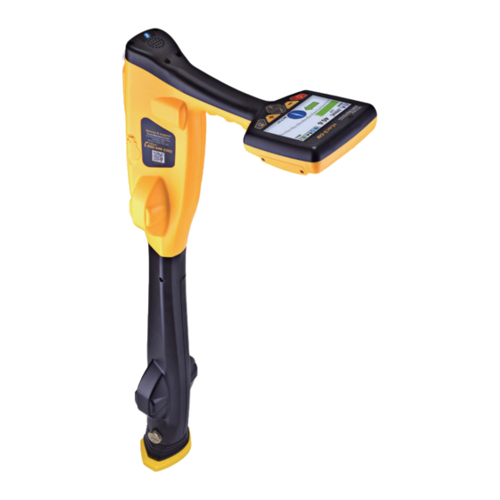
Receiver Functions and Operations 3. vLoc3-DM Receiver Functions and Operations vLoc3-DM Receiver Overview vLoc3-DM Receiver (with low-frequency sensor foot attached) Mini-USB cable Li-ion battery Charger AA Alkaline batteries Alkaline battery holder Power cable for charger vLoc3-DM Low-Frequency Sensor Sensor Blanking Plate... -
Page 14: Dm Low-Frequency Sensor Foot
The device at the bottom of the locator tube is the DM low-frequency sensor foot. This device is used to detect the low- frequency component (frequencies between 3Hz and 8Hz). These are the vLoc3-DM current mapping frequencies. When the low-frequency mapping is not required, for instance, if the equipment is being used for pipeline locating but not defect mapping, the low=frequency sensor can be removed. -
Page 15: The Vloc3 Series Keypad
Receiver Functions and Operations Rechargeable batteries are supplied with a mains charger that is specific to the batteries. Avoid using other manufacturers’ chargers as these may damage the battery pack and result in overheating. To charge the rechargeable batteries, first make sure the pack is inserted in the receiver battery compartment. Charging is done with the battery inside the receiver. - Page 16 Receiver Functions and Operations Pushbuttons Locate Screen Measure Screen Graph Screen 13.5 80.8mA 0.19m 11dB 0.27m 98Hz 59’55.95961’’N 27.50m 59’55.95961’’W 4+8Hz 1.09mA 506mA 345.05m 0.00m +37.03m 0.00m On/Off On/Off On/Off Auto scale when this icon is shown Change frequency, long press...
-
Page 17: The Vloc3 Series User Menu
Receiver Functions and Operations The vLoc3 Series User Menu The user-configurable vLoc3 series receivers can be customized to suit the user’s preferences. The receivers have several features that can be switched on and off through the user menu. This section covering the user menu is split into four subsections;... -
Page 18: Setup - Operational
Receiver Functions and Operations Sound Configuration - Changes the sound configuration of the locate modes. Use the Enter key to select AM or FM. • In active locate modes: Frequency Modulated (FM) Sound pitch changes with signal strength Amplitude Modulated (AM) Sound volume changes with signal strength •... - Page 19 The DM Current Warning feature can be enabled or disabled using the “MyLocator3” app. Pipe Diameter - The vLoc3-DM receiver measures the distance to the center of the pipe. If the pipe diameter is entered the depth indicated will be the depth to the top of the pipe, i.e., the cover depth.
-
Page 20: Setup - Features
Internal - The vLoc3-DM has a factory-installed internal GPS module. It is low accuracy, typically +/-3m. Bluetooth - If the Blue tooth option is selected, the vLoc3-DM can be paired by Bluetooth with a more accurate GPS. More on this is described later in this manual. -
Page 21: Setup - Informational
Metrotech or one of its approved repair centers for investigation. Note that the vLoc3-DM low-frequency sensor foot is not tested during the self-test. To test this item use the unit over a known pipe and check measured values fall within the published specification. -
Page 22: Warnings And Alerts
Receiver Functions and Operations Warnings and Alerts Warning symbols accompanied by an audible sound and vibration in the handle unless configured otherwise in the MyLocator3 desktop app. Warnings can also be switched off in the setup menu. 61.4 4.5mA 1.2m... - Page 23 Receiver Functions and Operations Frequency 128Hz 480Hz 491Hz 512Hz 577Hz 815Hz 982Hz 1.02kHz 3. Navigate to the main menu and scroll until you see DFT. Select DFT by pressing the enter key. 4. Once the option is selected the receiver will automatically assess the user’s preselected frequencies.
-
Page 24: Vloc3 Series Locate Modes And Screens
Receiver Functions and Operations vLoc3 Series Locate Modes and Screens Note - The vLoc3 series user interface is under continual development. The screenshots described here may differ slightly from your screens. The vLoc3 series receivers give the user a choice of locating screens. -
Page 25: Classic Locating Modes (Response)
Receiver Functions and Operations Classic Locating Modes (Response) The vLoc3-DM receiver has an array of six antennas and these can be toggled through different configurations (modes) to provide different responses to the signals radiating from buried utilities. The modes are: Peak Mode Two horizontal antennas provide a “Peak”... - Page 26 Receiver Functions and Operations Peak with Arrows Response Mode The “Peak with Arrows” mode operates in the same way as the peak mode. It gives the largest meter deflection when directly over the line. However, the left/right indication arrows are also displayed.
-
Page 27: Alternative Locate Screens
Receiver Functions and Operations 3.10 Alternative Locate Screens As previously mentioned the vLoc3 series receivers have alternative locate screens. The following section describes the operation of these screens. It is left to the user to decide which is the best screen for a particular application. -
Page 28: The Transverse Plot Screen
Receiver Functions and Operations 6. There is a black line leading from the locator icon to the target line. The blue dot represents the target. Around the dot is a circle. The size of the circle indicates a confidence factor. The larger the circle the less confident the indicated position. -
Page 29: The Plan View Screen
Receiver Functions and Operations 3.10.3 The Plan View Screen The Plan View screen shows a picture as if you were viewing the line from above ground. When the red line is in the center and pointing forward/back you are directly over the line and pointing in the line's direction. - Page 30 Receiver Functions and Operations 4. If the target is off the screen an arrow will appear on the screen to help direct you to the target line. 4.5mA 1450cm 1.2m 32.8kHz 5. As long as the locator is detecting a valid signal, the depth (or current) will be available regardless of locator orientation, i.e., the locator does not need to be aligned with the target line in the forward back orientation.
-
Page 31: Using The Vloc3-Dm Receiver
Using the vLoc3-DM Receiver 4. Using the vLoc3-DM Receiver Passive Locating The compass indicator is not active in passive locate modes. Passive locating refers to the process of detecting signals that naturally occur on pipes and cables. These tend to fall into two categories, radio signals and power signals. -
Page 32: Detecting Radio Signals
Using the vLoc3-DM Receiver Note that there will be no sound from the speaker until the meter reading is above approximately 10% of the full scale. 4. Keeping the vLoc3 receiver vertical walk across the area to be checked keeping the orientation so that the blade is in line with the direction of walking (See diagram above). -
Page 33: Active Locating - Applying The Locate Signal Using The Loc3, 25-Watt Transmitter
Using the vLoc3-DM Receiver Active Locating - Applying the Locate Signal using the Loc3, 25-Watt Transmitter Active locating uses a transmitter to apply a precise frequency to a pipe or cable, then uses a receiver turned to detect the signal being radiated at that precise frequency. -
Page 34: Transmitter Signal Clamp (25-Watt Transmitter)
Using the vLoc3-DM Receiver Switch on the transmitter by pressing and holding the on/off button down for a couple of seconds. Select the desired frequency depending on the application. Check for a good connection by either noting the mA output on the LCD or noting the change in tone rate when disconnecting and then reconnecting the red lead. -
Page 35: Locating A Pipeline
Using the vLoc3-DM Receiver When applying a clamp close to a grounding point where multiple grounds or a grounding bus exists, ensure that you place the clamp around the target line and not to the ground bus/other grounds. Doing this will help focus the applied signal on the target line. -
Page 36: Pinpointing
Using the vLoc3-DM Receiver 13.5 80.8mA 11dB 0.27m 98Hz 0.00m Keeping the receiver pointing at the connection point walk around the connection point for a full 360 degrees. The reading on the receiver signal strength meter will rise and fall as it passes over: •... -
Page 37: Taking Depth And Current Readings (Information Screen)
Storing the Results The vLoc3-DM current reading will continue to be updated approximately every second unless “Static” is chosen in the User setup of “DM Current.” This is done so that fluctuations in readings can be identified, allowing the user to wait until stable readings are shown before recording the result. -
Page 38: Clearing The Log
Deleting logs..Are you sure? Graphing results on the screen The vLoc3-DM has an onscreen graphing facility. Access to this facility is through the info screen. Press the “enter” key when in the “Info” screen. 0.75m 59’55.95961’’N 27.50m... -
Page 39: The Walk-Back Feature
Using the vLoc3-DM Receiver Horizontal Zoom – Allows the horizontal axis to be zoomed. Use the”+” and “-“ soft keys to zoom the horizontal axis. Vertical Zoom – Allows the vertical axis to be zoomed, use the”+” and “-“ soft keys to zoom the vertical axis. -
Page 40: Signal Direction Precision Identification
Using the vLoc3-DM Receiver 4.10 Signal Direction Precision Identification When a transmitter is connected to a target line the signal travels along it and finds the easiest way to travel back, usually via the ground and ground stake. However, the signal will often travel back along adjacent cables or pipes as these can offer an easier route. - Page 41 Using the vLoc3-DM Receiver 163mA 50°42′59.90570′′N 27.50m 3°26′35.54358′′W 0.54m 163mA A short press of the Return pushbutton will synchronize the system and return it to the locating screen. The green forward arrow will light and not be flashing, indicating the receiver is locked onto the signal. The system is now synchronized.
-
Page 42: Using The A-Frame Fault Finder
The A-frame is used to pinpoint coating defects along the pipeline. It does this by measuring the voltage in the ground caused by the vLoc3-DM signal current entering the pipe at a fault. It is necessary to make physical/electrical contact with the ground. The A-frame has two spikes to facilitate this. -
Page 43: Fault Finding Method
Using the A-frame If the approximate position of a defect has been identified by the vLoc3-DM using the current gradient technique, start an A-frame survey approximately 20 meters before this point. Place the A-frame on the ground so that the spikes puncture the ground, and with the A-frame in line and over the pipe the green spike pointing toward the suspected fault. -
Page 44: Using The A-Frame Where There Are Many Defects Such As Porous Coating
Using the vLoc3-DM Receiver At the null point the arrows will reverse, this is the location of the defect. Repeating the procedure across the pipeline will help pinpoint the defect in the other plane. See the following diagram. Sometimes it is not possible to gain access to the pipe position. If this is the case walking along the pipe route a few meters to one side can very often produce good results. - Page 45 Using the vLoc3-DM Receiver Taking DM current readings when using the A-Frame. With both the A-Frame and Low-frequency foot fitted it is possible to take DM current readings while remaining in the A-frame mode. This allows the operator to undertake ACVG and current gradient (CAT surveys) at the same time.
-
Page 46: Loc3 25-Watt Transmitter Functions And Operation
Loc3 25-Watt Transmitter Functions and Operation 5. Loc3 25-Watt Transmitter Functions and Operation This section of the manual covers the 25-Watt Loc3-25Tx transmitter. The Loc3, 25-Watt Transmitter Overview The 25-watt transmitter is a rugged portable transmitter powered by a Li-ion rechargeable battery. Loc3-25Tx Transmitter Li-ion battery tray Carry bag... -
Page 47: Pushbuttons
Loc3 25-Watt Transmitter Functions and Operation Pushbuttons On/Off control Frequency selector Information (Volume, Volts, Ohms, Multi-frequencies LCD Contrast, Receiver Link, Frequency menu and About screen) Output decrease/Navigate through the menu Output increase/Navigate through the menu Transmitter Information Pushbuttons Press the i button to access the transmitter settings and menu. Use the + and –... -
Page 48: Transmitter Batteries
Loc3 25-Watt Transmitter Functions and Operation All connections to the transmitter are made through the connection block. The connection block consists of: • Output socket - For the direct connection lead or transmitter signal clamp. • Fuse - Protects the transmitter from receiving up to 250V from the target line. •... -
Page 49: Removing And Installing The Battery Tray
Loc3 25-Watt Transmitter Functions and Operation Battery Charger - Is supplied with the 25-watt transmitter. Optional 12-volt DC Power Lead - This 30ft/90m lead can be used to power the 25-watt transmitter when connected to a target line at high output levels for extended periods. -
Page 50: Transmitter Modes
Loc3 25-Watt Transmitter Functions and Operation Transmitter Modes WARNING Always connect the transmitter to the target line following your company's procedures. These operations should only be performed by authorized personnel. Always make connections before switching on the unit. Turn the transmitter off before disconnecting. When the 25-watt transmitter is powered on without connection leads a “NO CONNECTION”... -
Page 51: Clamp Mode
Loc3 25-Watt Transmitter Functions and Operation 5.8.2 Clamp Mode The transmitter signal clamp is a precise way to apply the locate signal. Clamps are generally used when it is impossible to access the conductor to make a direct connection, but there is access to place the clamp around the cable. Clamps are also used when it is not safe to connect because the target cable is live carrying electricity. -
Page 52: Most Used Frequencies (Frequency Selection) Feature
Loc3 25-Watt Transmitter Functions and Operation The transmitter will always revert to first level output when switched on as a power-saving feature. In most circumstances this output level is sufficient. Increasing the output power unnecessarily will reduce battery life. All other settings remain the same as the last setting used. -
Page 53: Multi-Frequency Mode For Direct Connection
Loc3 25-Watt Transmitter Functions and Operation 5. After selecting the frequencies press the “i” pushbutton again to exit the “Frequency Menu” and return to the main display. 6. A particular frequency in the chosen list of frequencies can be selected from the screen by pressing the “f” pushbutton until the wanted frequency is displayed at the top of the main screen. -
Page 54: Loc-150Tx (150-Watt) Transmitter Functions And Operations
Loc-150Tx (150-Watt) Transmitter Functions and Operations 6. Loc-150Tx (150-Watt) Transmitter Functions and Operations Transmitter Overview Loc-150Tx Transmitter AC power cord Ground stake Signal Output Cable DC power cord Ref. Control Function Power To power on/off the unit LCD Display View menu status and information from the transmitter - Rotate rotary switch to select output current Output Current/Active-Standby - Press and hold to power on or standby... -
Page 55: Display
Loc-150Tx (150-Watt) Transmitter Functions and Operations Display ELF3-4Hz/8Hz/98Hz ELF3-4Hz/8Hz/98Hz 2.35 I OUT: 2339 2339 DC: 30 V PWR IN: 165 W POWER LIMIT! V OUT: 33 V VOLTAGE LIMIT! 3000 mA 3000 mA Main Screen Status Screen Power Limit = The Overpower alarm will be shown on the display when the transmitter's output power rating is reached (150W or 50W if 12-28Vdc input is used). - Page 56 Loc-150Tx (150-Watt) Transmitter Functions and Operations 2. Switch off the CP transformer rectifier and allow the residual voltage to dissipate. It may be a few seconds or a few minutes depending on the pipe condition. Standard CP Station Connections Mains Socket Station DC Output 3.
-
Page 57: Connecting To The Pipe When There Is No Access To A Cp Station
Loc-150Tx (150-Watt) Transmitter Functions and Operations 6. The output lead connected to the transmitter connects the red wire to the lead connecting to the pipeline. Connect the Black wire to the lead connecting to the anode bed. See the diagram above. If the output leads are white and green, the white cable should be connected to the pipe. -
Page 58: Output Current Select
Loc-150Tx (150-Watt) Transmitter Functions and Operations Output Current Select There are seven current settings: • 100mA • 300mA • 600mA • 1A • 2A • 3A • 4A (when a single locate frequency is selected) Choosing the correct setting for a particular application depends on many factors. As a general rule the higher settings are better. -
Page 59: Using External Gps
• Switch on the external device. • Switch on the vLoc3-DM and enter the User setup menu by a long press on the “i” button. • Use the “+” and “-” keys to scroll down to the option “Bluetooth Pairing.”... - Page 60 (see the previous section on Bluetooth devices). Once paired with an external device the vLoc3-DM will await valid GPS data from the external device. The GPS icon will turn green when a valid GPS signal is detected. The change can take from a few seconds to a few minutes depending on the device and whether it is doing a cold or hot start.
-
Page 61: Transferring Data From The Locator
Transferring Data from the Locator 8. Transferring Data from the Locator This section of the manual covers using the MyLocator3 App with the vLoc3 series of receivers. The vLoc3 receiver will need to be connected to the computer running the MyLocator3 program. Connect your vLoc3 receiver to your computer via the supplied mini-USB cable. -
Page 62: Application Update
Transferring Data from the Locator 8.2.2 Application Update Every time the MyLocator3 Application is started its version number is checked against the latest version available on the Vivax- Metrotech server. The user is notified if an update is available as shown below. This feature will only be available if the computer is online. -
Page 63: Locator Firmware Update
Transferring Data from the Locator 8.2.3 Locator Firmware update Each time a locator is connected to the PC, its firmware version is checked against the latest version available on the Vivax- Metrotech server and the user is notified if an update is available as shown below. This feature will only be available if the computer is online. -
Page 64: Splash Screen
Transferring Data from the Locator If it is only required to export a portion of the log, for instance, a survey on a particular day, use the data log scroll facility at the bottom left of the display to scroll through to the start date/time. Note the log number and then scroll to the end date/time and note this log number. -
Page 65: Frequencies Page
Transferring Data from the Locator 8.2.7 Frequencies Page The “Frequencies” page will allow the user to refine which frequency modes are available when the locator F-key is pressed and which frequencies appear on the locator menu. ™ Page 57 of 65... -
Page 66: Menu Settings
Transferring Data from the Locator 8.2.8 Menu Settings The “Menu Settings” page allows the user control over which menu items appear on the locator and the menu item's initial setting when the locator is first used after configuration. The menu items with a right-pointing arrow can be expanded to reveal additional sub-menu items. -
Page 67: Interpreting Results
Introduction Using the vLoc3-DM system can quickly and efficiently assess the general coating of a pipeline network. It can help identify defects and possible shorts to other structures. It can be used as a tool to prioritize and plan work on the network. However, unless care is taken when interpreting the results misinterpretation can lead to unnecessary work and expenses. -
Page 68: Checking For Distorted Fields
• Passing Vehicles The sensing devices used to detect the 3Hz vLoc3-DM profiling signal are very sensitive to low frequencies. Vehicles passing very close to the receiver will disturb the earth’s magnetic field and distort the received signal. Try to take measurements when there is a gap in passing vehicles. -
Page 69: Viewing Data
Interpreting Results Viewing Data Upload the data from the vLoc3-DM receiver as described previously in section Upload Data Files. Files can be saved in .txt, .kml, or .shp formats. 9.3.1 Viewing. xls Files Open an Excel spreadsheet and open the desired file. Something similar to the screen below will be displayed. The data is now in the form of an Excel spreadsheet and can be manipulated to create suitable graphs. -
Page 70: Viewing .Kml Files
Interpreting Results 9.3.2 Viewing .kml Files To view .kml files it is necessary to have Google Earth installed on the host computer. If not already done please visit the Google Earth Web and install the latest version. To launch a .kml file, double click on the selected file. If connected to the web and if the Google Earth application is installed on the host computer Google Earth will automatically launch and zoom to the site location. -
Page 71: Interpreting Graphs
Interpreting Results Interpreting Graphs Two types of graphs can be plotted. These can either Linear or Logarithmic In both cases it is important to look at the trend of the graph rather than individual points. This is because the signals radiating from a pipe can be affected by many external influences such as: •... -
Page 72: 10. Care And Maintenance
10.2 Checking Functionality The vLoc3-DM system can be checked using a simple test procedure. It requires an area clear of pipes and cables and free from metallic structures such as metal tanks, metal railings, and reinforced concrete. A 40m square loop of wire needs to be set out on the ground with a non-metallic structure placed at 1m above the cable and at the midpoint of one of the straight sections. -
Page 73: 11. Glossary
Glossary 11. Glossary Active Locate A locate where a transmitter is used to apply a signal to a buried pipe or cable, the position of which is then located by a receiver tuned to the same frequency. Active Signal A signal applied by the locator transmitter to a buried line. Typical this is a very precise frequency. - Page 74 Notes: Vivax-Metrotech Corporation 3251 Olcott Street, Santa Clara, CA 95054, USA Toll-Free: 1-800-446-3392 Phone: +1 (408) 734-1400 Website: www.vivax-metrotech.com ™...
Need help?
Do you have a question about the vLoc3-DM and is the answer not in the manual?
Questions and answers