Table of Contents
Advertisement
Quick Links
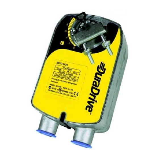
4Nm Spring Return Actuator
APPLICATION AND USE
Spring return rotary actuators MX41-7 have a rotary output for
direct coupling to air dampers. Models are available for on/off
Operation from 230Vac or 24Vac power supplies and 24Vac fl o-
ating point control.
•
Direct coupling to all normal dampers without mounting
brackets or linkage kits - saves site time;
•
Universal clamp provides direct mounting to dampers shaf-
ts up to 19mm diamters up to 13mm square;
•
Case IP 54;
•
Clockwise and counterclockwise rotation available, deter-
mined by Left or Right hand mounting;
•
Spring tensions whilst the damper is being operated;
•
Positive spring return operation, for example under power
failure;
•
Provides 95° of rotation; rotation limiting available;
•
Visual position indicator;
•
Optional built-in auxiliary switches to provide for interfacing
or switching;
•
Cable gland and Blanking plugs supplied fi tted;
•
MS4x-7xxx series provided with Left/Right switch for selec-
tion of direct or reverse action control mode.
ACCESSORIES
AM-703 Input Rescaling Module, adjusts signals to 2-10Vdc,
zero and span adjustment.
AM-705 Positioner
AM-706 Min and/or Manual Positioner for fl ush panel mount.
AM-710 Universal clamp for shaft from 16 up to 19mm
1
Issue
st
ISO 9001
09/13
CONTROLLI S.p.A.
16010 SANT'OLCESE Genova - Italy
Tel.: +39 01073061
E-mail: info@controlli.eu
1
Fax: +39 0107306870/871
Web: www.controlli.eu
MX40-7
DBL153e
Advertisement
Table of Contents

Related Manuals for Controlli DuraDrive MX40-7


Summary of Contents for Controlli DuraDrive MX40-7
- Page 1 AM-706 Min and/or Manual Positioner for fl ush panel mount. AM-710 Universal clamp for shaft from 16 up to 19mm Issue 09/13 DBL153e CONTROLLI S.p.A. 16010 SANT’OLCESE Genova - Italy Tel.: +39 01073061 Fax: +39 0107306870/871 ISO 9001 E-mail: info@controlli.eu...
- Page 2 • Reorient or relocate the receiving antenna. OPERATION • Increase the separation between the equipment and re- Warning - This are spring return actuators. Keep clear of all ceiver. moving parts at all times. • Connect the equipment to an outlet on a circuit different The direction of operation of the spring return function and mo- from that to which the receiver is connected.
- Page 3 • Determine the best orientation for the universal mounting Test for adequate shaft length by sliding the actuator over clamp on the back of the actuator. The best orientation pro- the shaft. The shaft should extend at least 3mm through vides the easiest access to the two nuts on the V-clamp.
- Page 4 10. Loosen the universal mounting clamp (making sure not to WIRING DIAGRAMS move the damper shaft) and rotate the actuator approximately Class 2 control and power lead wiring must be routed separa- 5° in the direction which would open the damper. tely from line voltage wiring and any other non-class 2 circuits.
- Page 5 FLOATING POINT CONTROL - 24V AUXILIARY SWITCHES (IF FITTED) Actuator types: MA40-7041-G01, MA40-7043-G01, MF40- 7043-G01 and MS40-7043-G01 have one SPDT 6A (1.5A) 230V auxiliary switch built-in for end position indication or sy- stem interlock functions. Use an isolator with a minimum con- tact gap of 3mm (conforming to EN 60335-1) to isolate the MA40-7041 series from the mains supply.
Need help?
Do you have a question about the DuraDrive MX40-7 and is the answer not in the manual?
Questions and answers