
Related Manuals for Allmatic CT3IND


Summary of Contents for Allmatic CT3IND
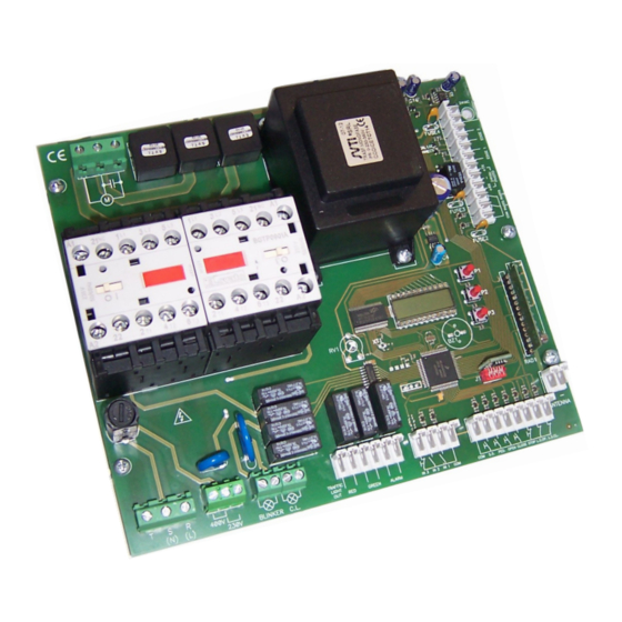
- Page 1 CONTROL UNIT CT3IND Programmable Control board for sliding gates Manual for installation 1 / 10 6-1622598 REV.3 23/09/2020...
- Page 2 400Vac, in a simple and complete way; it is designed to satisfy all possible needs. The CT3IND is safe because it is designed with a sense that enables the detection of possible obstacles along the run, furthermore it has a motor protector that enables to protect the motor in case of over current.
- Page 3 2. Connections Connect the power supply cable between the Do not connect the card directly to the electric clamps 1, 2 and 3 of the control unit if a three- network. Put a device that can ensure the S (N) phase power supply 400 Vac is used.
- Page 4 CLOSE INPUT COM. Connect the button CLOSE between the clamp 21 and 25 of the control unit. CLOSE. ATTENTION: Leave it open if not used. STOP INPUT COM. Connect the NORMALLY CLOSED contact of the STOP between the clamp 21 and 26 of the terminal box.
- Page 5 3. Preliminary checks and general warnings 3.1 General warnings Before powering the control unit , carry on the following checks: • The electric installation and the logic functioning should be compliant with the law in force. • Avoid putting the connection cables of the buttons, security devices and inputs close to those of the power supply of the control unit and of the motor.
- Page 6 Under the normal functioning conditions, the display is in the main page where the state of the inputs is displayed. The N.C. inputs are represented by vertical segments. The N.O. segments are reprsented by horizontal segments. EDGE 2 L.S.OP. L.S.CL. EDGE 1 S.S.
- Page 7 4.3 Menu “basic settings” From press the key P2 to enter the menu “basic settings” MENU SELECTABLE VALUES DESCRIPTION DEFAULT MEMO min-max Enables to set the working time of the automation. 5 s — 600s 30 s ...
- Page 8 MENU SELECTABLE VALUES DESCRIPTION DEFAULT MEMO min-max Automatic reclosing function from photocells. The gate closes automatically 3 seconds after the passing through the photocells. ON — OFF The function can be activated only if the automatic reclosing os activated. Dead man function OFF: dead man function disabled.
-
Page 9: Faults Diagnostics
40%. Fault of motor thermal. To use the automation again leave the motor still until the alarm ceases. TECHNICAL FEATURES - CT3IND CONTROL UNIT Power supply 230 Vac +-10%, 50Hz singlephase / 400 Vac 50Hz Three-phase Photocells power supply... - Page 10 CAUTION! – the regulations in force at local level may envisage heavy sanctions in case of abusive di- sposal of this product. ALLMATIC S.r.l 32026 Borgo Valbelluna - Belluno – Italy Via dell’Artigiano, n°1 – Z.A. Tel. 0437 751175 – 751163 r.a. Fax 0437 751065 www.allmatic.com - E-mail: info@allmatic.com 10 / 10 6-1622598 REV.3 23/09/2020...
Need help?
Do you have a question about the CT3IND and is the answer not in the manual?
Questions and answers