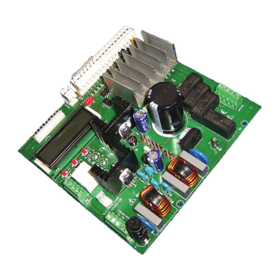
Summary of Contents for Allmatic CT INVERTER AM
- Page 1 CT INVERTER AM CONTROL UNIT Programmable control board for sliding gates with inverter technology Manual for installation...
- Page 2 1. Introduction The Single-phase control unit CT INVERTER AM is a device suitable for operating and controlling the sliding gate in a way easy and complete; it is designed in order to satisfy all possible needs. The inverter on board allows to set the maximum torque limits along with the possibility to modify the frequency (the speed of the motor).
- Page 3 2. Collegamenti ANTENNA INPUT Connect the signal cable of the antenna to the The presence of the metallic parts or humidity in the clamp 1 of the terminal board. walls could have negative influences on the range Connect the ground of the antenna to the clamp of the system.
- Page 4 PHOTOCELLS POWER SUPPLY Connect the clamp 16 of the control unit to the The photocells test test is activated by the MENU A. clamp + of the power supply of the photocells ATTENTION: the control unit gives a voltage of 24 receiver.
-
Page 5: Language Setting
3.1 Activation and selection of the programming menu The control unit CT INVERTER AM is equipped with THREE user menus (MENU A, MENU B, MENU C), by which it is possible to regulate, program and modify all functional parameters. Follow the indications on the display during the programming phases. - Page 6 3.2 Programming menu A (key P1)- List of parameters The following table lists the entries of menu A and reports a short description of the parameters that can be adjusted; refer to paragraph ADVANCED FUNCTIONS for more details Timed closure of the gate (only from total or partial opening) Auto OFF: disabled MENU A...
- Page 7 3.3 Programming menu B (key P2) - List of parameters The following table lists the entries of menu A and reports a short description of the parameters that can be adjusted; refer to paragraphs dedicated to each function for more information Allows to move the gate at low speed by using the keys located on the control board.
-
Page 8: Preliminary Checks
4. Preliminary checks The preliminary checks must be carried out only by professionals and by paying maximum attention. The correct wiring of the motor and the limit switches is very important for the correct functioning of the automation. Unlock the motor and supply the system with power only Check the status of the LEDs input by considering that all after controlling the wiring connections and checking the normally closed (NC) inputs must have their corresponding... -
Page 9: Advanced Functions
6.2 Learning the partial run (Menu B – Ped. Position) Learning the partial run allows to define the position of partial opening that allows the pedestrians accessing (PED command) Check that the adjustment of the torque and the speed of the gate are set before carrying out the learning phase. Check that the gate is closed before starting the learning phase. - Page 10 11 Housing for radio receiver The unit disposes of a molex connector to house an ALLMATIC radio receiver. The first channel of the receiver is associated to the wired com- mand S.S., whereas the second radio-channel (if it is present) is associated to wired command PED.
- Page 11 9 Tips for a successful installation 9.1 High speed movements PROBLEM SOLUTION Raise the torque supplied to the motor until problem is solved The motor stops for the effort during the movements High Torque OP, High Torque OP ...
- Page 12 For connecting the card and the motors we recommend to use cables with double isolation as in compliance to the laws in force; the minimum cross section of the single conductor must not be less than 1,5 mm² and not more than 2.5mm². TECHNICAL FEATURES - CT INVERTER AM Power supply 230 Vac +15%, -15% ;...


Need help?
Do you have a question about the CT INVERTER AM and is the answer not in the manual?
Questions and answers