Table of Contents
Advertisement
Quick Links
P470 Electronic Pressure Control with Display
Product/Technical Bulletin
The P470 Electronic Pressure Control with Display is a
single-stage, on and off, electronic pressure control
with a single-pole, double-throw (SPDT) output relay.
You can field-set the P470 control to operate in one of
the following three pressure ranges, as either an open-
high or open-low control: 0 psi to 100 psi, 0 psi to 500
psi, or 50 psi to 750 psi.
The P470 control has a large LCD that displays the
sensed pressure, other system-status indicators, and
adjustable setpoints in the programming mode. The
P470 control has a lockable, three-button touchpad for
adjusting setpoints, and a front-panel LED that
indicates the output relay status.
The P470 control uses a P499 or P599 Series
Electronic Pressure Transducer and a WHA-PDK3
wiring harness to sense system pressure. This
arrangement eliminates almost all refrigerant leaks
because there are no capillaries or bellows to break or
fail. See Ordering information for information about
specified pressure transducers.
Features and benefits
•
Easy to read LCD—Clearly displays the sensed pressure and other control information. In many situations,
pressure may be monitored without applying gauges to the controlled equipment.
•
Three field-selectable pressure ranges between 0 psi and 750 psi—Flexibly covers most HVACR pressure
applications with three field-selectable pressure ranges: 0 psi to100 psi with 5 psi minimum differential, and 0
psi to 500 psi or 50 psi to 750 psi with 20 psi minimum differential.
•
24 VAC and 120 VAC or 208/240 VAC models—Increases application options, with two controls that cover
most common voltages.
•
Lockable, three-button, front-panel touchpad—Deters tampering and over-adjustment of control settings by
unauthorized personnel.
•
Built-in, adjustable, anti-short cycle delay—Reduces compressor short cycling and nuisance lockouts that
can extend compressor life.
•
Uses an economical and versatile transducer and wiring harness—Eliminates many of the constraints of
capillary control applications and supports up to a 100 ft (30.5 m) cable between a control and transducer.
P470 Electronic Pressure Control with Display Product/Technical Bulletin
Part No. 24-7664-2004, Rev. C
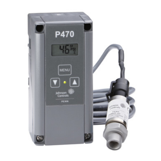
Figure 1: P470 Electronic Pressure Control with
transducer and wiring harness
1
Code No. LIT-125528
Issued October 2018
t.
Advertisement
Table of Contents

Related Manuals for Penn P470


Summary of Contents for Penn P470
- Page 1 (SPDT) output relay. You can field-set the P470 control to operate in one of the following three pressure ranges, as either an open- high or open-low control: 0 psi to 100 psi, 0 psi to 500 psi, or 50 psi to 750 psi.
-
Page 2: Operation Overview
You can use a maximum of four P470 controls wired to or protect against failure or malfunction of the P470 a single P499 or P599 transducer. For example, high- control. - Page 3 The open-high icon is shown here in gray to illustrate its position on the LCD.) You can use the P470 control to establish a variety of control settings, position jumpers inside the control and Touchpad adjustable setpoints use the three-button touchpad to change setpoint values.
- Page 4 Johnson Controls® and PENN® controls. terminals, SP2 and COM, on the upper terminal block You can mount the P470 control on a 35 mm DIN rail. (TB3). When the secondary setpoints activate, S2 See Dimensions for more information. The P470...
- Page 5 Wiring The P470 control uses a P499 or P599 transducer to generate the 0.5 VDC to 4.5 VDC input signal. The WARNING: Risk of Electric Shock. transducer is wired to the control at the terminal block, Disconnect the power supply before making TB3, on the upper-left of the circuit board.
- Page 6 Figure 5: Typical wiring for 120 VAC Figure 7: Wire multiple P470 controls in parallel applications of the P470EB-1 Pressure Control with a single transducer Figure 6: Typical wiring for 208/240VAC Adjustments applications of the P470EB-1 Pressure Control This section provides instructions for setting up and adjusting the P470 control using the internal jumpers and front panel touchpad.
- Page 7 Figure 8 and Figure 9 as guides. Figure 9: Jumper positions for locking touchpad and establishing the P470 control’s 1. Disconnect all power sources to the P470 control. operating pressure range 2. To remove the control’s cover, loosen the four captive cover screws.
- Page 8 Note: If you do not press Menu within 30 seconds after you change a setpoint or time-interval value, delay time-interval the control returns to the previously programmed To change the P470 control setpoint values and anti- setpoint or time interval value. short cycle delay time-interval, complete the following steps:...
-
Page 9: Troubleshooting
P470 control. procedures. 1. Check for proper supply voltage to the control. a. Before powering control and equipment, check that all of the wiring is correct and all of the connections are tight. P470 Electronic Pressure Control with Display Product/Technical Bulletin... - Page 10 See Figure 14 and Figure 15. = Supply voltage to the transducer, which is a. Set the P470 control’s anti-short cycle delay to measured in Step 2a. zero, and make sure that the control operates = Transducer pressure range maximum on the primary setpoints, S1.
- Page 11 Disconnect the wires from the P470 control’s output relay, and make sure the control is Figure 14: LED status for open-high controls powered. d. The pressure displayed on the control should equal the pressure measured at the transducer with a pressure gauge. If the two pressure values differ greatly, check the gauge for accuracy.
- Page 12 If the LED does not respond as indicated, replace the control. IMPORTANT: The P470 control is not repairable. Do not attempt to repair the control if it is defective or functioning improperly. Contact a Johnson Controls and PENN sales representative to order a new control. See Ordering information.
-
Page 13: Display Explanation
The Err display code does not flash. Repair information The P470 Electronic Pressure Control and P499 or P599 Series Electronic Pressure Transducers are not field repairable. To determine the problem, perform the troubleshooting procedures in sequence. If the problem is with the control or transducer, contact a Johnson Controls or PENN sales representative for a replacement. -
Page 14: Ordering Information
Ordering information Note: P470 controls do not include a transducer or wiring harness. A P499 or P599 transducer and a wiring harness must be purchased separately. Match the transducer to the selected pressure range. See Table 1. Table 3: Ordering table for P470 controls, transducers, and wiring harnesses... -
Page 15: Technical Specifications
Cet appareil numérique de la Classe (A) respecte toutes les exigences du Règlement sur le matériel brouilleur du Canada. www.penncontrols.com ® Johnson Controls and PENN are registered trademarks of Johnson Controls in the United States of America and/or other countries. All other trademarks used herein are the property of their respective owners.
Need help?
Do you have a question about the P470 and is the answer not in the manual?
Questions and answers