Table of Contents
Advertisement
Quick Links
Advertisement
Table of Contents

Related Manuals for Lenze C25BAYCB


Summary of Contents for Lenze C25BAYCB
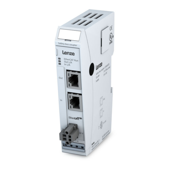
- Page 1 C25BAYCB Translation Operating Instructions c250−S Safety bus coupler...
-
Page 3: Table Of Contents
Hazard and other Warnings ..............6 1.3.2 Other Notices ..................7 Introduction ......................10 EtherCAT® — Ethernet Control Automation Technology ........10 Lenze Safety System ..................10 System Description ....................11 General conditions of use .................. 11 Dimensions ......................11 Mechanical Design ..................... 11 3.3.1... -
Page 4: Preface
This Operating Instructions contains general Information for parameterization, configuration and diagnosis of the Lenze Safety System. Target Group This Operating Instructions is directed to Persons, who project and setup the Lenze Safety System with the Engineering Tool Information Information and Tools about the Lenze Products can be found in the Internet http://www.lenze.com ►... -
Page 5: Reliability, Safety
Scope For reasons of personal safety and to avoid material damages when working with or handling this Lenze product, you are advised to take heed of the notes and information contained in this instruction manual. Target Group of Operating Instructions This instruction manual contains all information necessary for the use of the described product (control device, control terminal, software, etc.) according to instructions. -
Page 6: Hazard And Other Warnings
Preface 1.3.1 Hazard and other Warnings Despite the actions described in section 1.3, the occurrence of faults or errors in electronic control units - even if most highly improbable - must be taken into consideration. Please pay particular attention to the additional notices which we have marked by symbols throughout this instruction manual. -
Page 7: Other Notices
Preface 1.3.2 Other Notices Informations This symbol draws your attention to additional information concerning the use of the described product. This may include cross references to information found elsewhere (e.g. in other manuals). Safety Our products normally become part of larger systems or installations. The information below is intended to help you integrate the product into its environment without dangers to humans or material/equipment. - Page 8 • Repairs may only be carried out by qualified Lenze personnel. Otherwiese warranty is lost. • Spare parts: Only use parts approved of by Lenze. Only genuine Lenze modules must be used in modular controllers. • Modular systems: always plug or unplug modules in a power-down state. You may otherwise damage the modules or (possibly not immediately recognizably!) inhibit their functionality.
- Page 9 Preface Electrical Immission Safeguard To eliminate electromagnetic interference, connect the control system to the protective earth conductor. Practice best cable routing. Cable Routing and Wiring Keep power circuits separate from control circuits: • DC voltages 60 V ... 400 V •...
-
Page 10: Introduction
Lenze Safety System The Lenze Safety System is a system of I/O modules for connecting the process signals to an EtherCAT network. The Lenze Safety System consists of the Safety bus coupler and a range of other modules. -
Page 11: System Description
System Description System Description General conditions of use This section describes the general characteristics of Safety modules which are important for the installation, wiring and troubleshooting. You can find an overview of the system properties in section 5.1.1 System features on page 21. Dimensions Mechanical Design The Safety bus coupler and the Safety I/O-modules differ in their connectors and indicators,... -
Page 12: Earth
System Description 3.3.1 Earth Connect the Safety modules to earth by attaching the metal housing to operative earth. Since the operative earth connector dissipates HF currents, it is of utmost importance for the module's noise immunity. HF interference is dissipated from the electronics board to the metal housing. The metal housing therefore needs to be suitably connected to an operative earth connector. -
Page 13: Installation
System Description 3.3.2 Installation The modules of the Lenze Safety System are intended for mounting rail installation (DIN EN 50022, 35 x 7.5 mm). Installation position The mounting rail is placed horizontally and the female connector strip of the modules face forward. - Page 14 System Description To snap on a single module 1. Push up the module against the mounting rail from below, allowing the metal spring to snap in between mounting rail and mounting area as illustrated. 2. Push the module against the mounting wall until is snaps in. Figure 4: Rail mounting of module To interconnect two modules 1.
- Page 15 System Description To take down a single module 1. Push the module up and against the metal spring located on the underside of the rail guide. 2. Tip the module away from the rail as shown in the illustration. 3. Pull the module down and out of the mounting rail. Unlock button Figure 5: Uninstall a module EDBC250SBC |1.1...
-
Page 16: System Power Supply
The power supply lines may not be connected by one supply terminal of the Lenze Safety Module to the next. In order to ensure trouble-free operation, the supply lines must be routed in star formation with the shortest possible lines from a central supply terminal to Lenze Safety Module. -
Page 17: Safety Bus Coupler
System Description 3.4.2 Safety Bus coupler A 2-pin plug-in terminal block with screw flange is used to connect the system supply to the bus coupler. Since the bus coupler supplies power to both the E-bus and the logic circuits of the Safety controller c250-S and the Safety I/O-modules, its power consumption depends on the Safety controller c250-S and the number of Safety I/O-modules connected. -
Page 18: Led "Io
System Description 3.5.3 LED "IO" Every I/O module has an LED labeled "IO". It indicates the state of the module's I/Os. Refer to the I/O module sections in this manual to know which states of a module are monitored and indicated. -
Page 19: Module
LVDS (E-bus) and gene rates the system Voltages required by the LVDS modules. The standard 100 Base Tx lines used for office communications network connect to the one side, the Lenze Safety modules for the process signals connect to the other. This is how the Ethernet EtherCAT protocol is retained right through to the load I / O modules. -
Page 20: Status Leds
Data type Explanation Undervoltage BOOL Low voltage (supplied power < 19,2V) Technical data General device date Function Connects a 100 Base-TX EtherCAT with the Lenze Safety modules. Generates the LVDS system voltages. Controller ASIC ET1100 Baud rate 100 Mbit/s Cable... -
Page 21: Appendix
Appendix Appendix Technical data (Overview) 5.1.1 System features General device date Fieldbus EtherCAT 100 Mbit/s Dimensions 25 mm x 120 mm x 90 mm (B x H x T) Housing mount aluminium Shield connected straight to module housing Installation 35mm DIN rail (top-hat rail) IO connection spring-assisted combi plug with mechanical ejector, 4 …... - Page 22 © 08/2017 | EDBC250SBC | .URj | 1.1 | TD15 Lenze Automation GmbH Postfach 10 13 52, 31763 Hameln Hans−Lenze−Str. 1, 31855 Aerzen GERMANY HR Hannover B 205381 Ü +49 5154 82−0 Ø +49 5154 82−2800 Ù lenze@lenze.com Ú www.lenze.com Û...
Need help?
Do you have a question about the C25BAYCB and is the answer not in the manual?
Questions and answers