Linx 5900 Manual
Hide thumbs
Also See for 5900:
- Quick start manual (81 pages) ,
- Manual (39 pages) ,
- How to use manual (34 pages)
Table of Contents
Advertisement
Advertisement
Chapters
Table of Contents

Related Manuals for Linx 5900


Summary of Contents for Linx 5900
- Page 1 An Introduction to the Operating Instructions for the Linx 5900 & 7900 Printers...
-
Page 2: Content Of Quick Start And 'How To
1.2 About the Quick Start and ‘How To...’ guides ................. 2 2 Content of Quick Start and ‘How To...’ guides................3 2.1 Linx 5900 & 7900 Quick Start Guide ..................4 2.2 ‘How To...’ guides ........................4 Page 1 of 7 FA69379–2 English... - Page 3 Operating Instructions for the Linx 5900 & 7900 Printers 1 Introduction This document provides an introduction to the Linx 5900 & 7900 Quick Start Guide and ‘How To...’ guides and the information they contain. 1.1 Health and Safety Make sure that you read and understand the Health and Safety information in the ‘Safety’...
-
Page 4: Table Of Contents
The following Quick Start and ‘How To...’ guides are available: • Linx 5900 & 7900 Quick Start Guide • How To Install and Set Up the 5900 & 7900 Printer (‘How To...’ guide 01) • How To Change the Print Settings (‘How To...’ guide 02) •... -
Page 5: Linx 5900 & 7900 Quick Start Guide
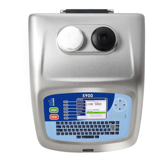
2.1 Linx 5900 & 7900 Quick Start Guide The Linx 5900 & 7900 Quick Start Guide helps you do the most common jobs on the 5900 and 7900 printers. The guide describes the layout of the printers, the controls, and the displays. - Page 6 (‘pixels’). You can use the Logo Editor to set each pixel to make a complete image. You can import logos to the 5900 printer via a USB memory stick.
- Page 7 13 How To Create a Remote Field This document describes how to create a remote field for the 5900 and 7900 printers. A remote field in a message reserves an area that you can use for data downloaded from a remote computer or other equipment.
- Page 8 MidiEC printhead. 21 How to Use the USB Connection This document describes how to use the USB connection of the 5900 and 7900 printers to save messages from the printer to a USB memory stick and transfer messages and logos to the printer from a memory stick.
-
Page 9: How To Install And Set Up The 5900 & 7900 Printer ('How To
How To Install and Set Up the 5900 & 7900 Printer... - Page 10 How To Install and Set Up the 5900 & 7900 Printer Contents 1 Installation............................. 2 1.1 Introduction ..........................2 1.2 Health and Safety ........................2 1.3 Equipment information......................2 1.4 Tools required......................... 2 1.5 Where to install the printer...................... 2 1.6 Connect to a power source.....................
- Page 11 7900 Printer 1 Installation 1.1 Introduction This document describes how to install and set up the 5900 and 7900 printers. You can use these instructions to move the printer to a new location or make changes to the production line setup.
- Page 12 How To Install and Set Up the 5900 & 7900 Printer Figure 1 shows the layout of the rear panel of the Linx 5900 and 7900 printers. 73017 Figure 1. Linx 5900/7900 printer rear panel Figure 1 shows the following items:...
- Page 13 PERSONNEL OR DAMAGE TO MACHINERY CAUSED BY INCORRECT OR FAULTY WIRING. 1.7 Fit the printhead to the production line You can set the printhead at any angle. Use a Linx printhead bracket to hold the printhead correctly and prevent vibration—a number of bracket types are available.
- Page 14 • Make sure that the conduit does not touch any sharp edges. • For dynamic applications (traversing), Linx recommends that you use a 4-metre conduit. Leave a loop in the conduit to absorb the movement as shown below. 69344 Figure 4. Printhead conduit with loop Page 5 of 25 FA69372–2 English...
- Page 15 7900 Printer 2 Product sensor setup The Linx 5900 and 7900 printers can use a product sensor to detect the presence of the product. Normally, the message is printed when the printer receives a trigger signal from the product sensor.
- Page 16 To maintain the IP65 rating of the 7900 printer, the connector of the product sensor must have an IP65 rating. Linx product sensors have a D-type connector that has an IP67 rating. CAUTION: Use only Linx-approved accessories. The EMC performance of the printer can change if you use other product sensors and cables.
- Page 17 7900 Printer 3 Line speed detection setup Linx recommends that you use a shaft encoder or dual trigger to detect the line speed on production lines where the speed can change. If your system has a fixed line speed, you can go to the next section.
- Page 18 To maintain the IP65 rating of the 7900 printer, the connector of the shaft encoder must have an IP65 rating. Linx shaft encoders have a D-type connector that has an IP67 rating. CAUTION: Use only Linx-approved accessories. The EMC performance of the printer can change if you use other shaft encoders and cables.
- Page 19 If the raster pitch in your application does not equal the Ideal Raster Pitch, you can adjust the Print Height setting to make the aspect ratio 1:1. NOTE: Not all message types listed in the Ideal Raster Pitch tables are available on the 5900 printer.
- Page 20 This value must be as close as possible to the required raster pitch. The table below gives the encoder pitch for standard Linx encoders and wheels. To calculate the encoder pitch for other gearing or drives, use the...
- Page 21 0.020 0.005 Figure 9. Encoder Pitch for standard Linx encoders and wheels The encoder pitch is multiplied by a whole number (or pitch factor) to give the actual raster pitch. Select an encoder and gearing to make the actual raster pitch close to the required raster pitch.
- Page 22 How To Install and Set Up the 5900 & 7900 Printer In this example, the required raster pitch is 0.378 mm. You can use a standard Linx encoder and wheel to try to match this value. &#"! Encoder/Gearing Encoder Pitch...
- Page 23 How To Install and Set Up the 5900 & 7900 Printer The following table shows the maximum encoder speeds for standard Linx encoders and wheels. 68546 Maximum Encoder Speeds (m/s) Encoder 333 mm 500 mm 200 mm 50 mm 304.8 mm p.p.r.
- Page 24 The Pulses/mm value is the number of pulses of the encoder output signal for every millimetre of the product movement. The following table shows the pulses per mm values for the combinations of Linx standard encoders and encoder wheels. 68550...
- Page 25 How To Install and Set Up the 5900 & 7900 Printer The value required for this example is as follows: 0.040 x (9 + 0.5) = 0.38 The printer changes the value to 0.36 when you press the OK key.
- Page 26 Maximum Print Speed = Actual Raster Pitch x Raster Rate Calculate: Maximum Encoder Speed = Encoder Pitch x Maximum Encoder Frequency (Maximum Encoder Frequency is 80 kHz for Linx standard encoders.) Make sure that the Maximum Line Speed (step 7) is less than the Maximum Encoder Speed (step 8).
- Page 27 How To Install and Set Up the 5900 & 7900 Printer 3.2 Ideal Raster Pitch tables NOTE: The rasters available depend upon the printer type (5900 or 7900) and the software configuration. 3.2.1 Midi and MidiEC printheads 69493 MIDI PRINTHEAD...
- Page 28 How To Install and Set Up the 5900 & 7900 Printer NOTE: The MidiEC printhead can print a maximum of three lines of text or graphics. The four line options shown in Figure 15 are not available. Page 19 of 25 FA69372–2 English...
- Page 29 How To Install and Set Up the 5900 & 7900 Printer 3.2.2 Ultima printhead 69494 ULTIMA PRINTHEAD Message Type Character matrices Ideal raster Maximum Maximum line pitch raster rate speed at ideal (no. of lines x H x W) raster pitch...
- Page 30 How To Install and Set Up the 5900 & 7900 Printer 3.2.3 Midi plus printhead 68589 MIDI PRINTHEAD Message Type Character matrices Ideal raster Maximum Maximum line pitch raster rate speed at ideal (no. of lines x H x W)
- Page 31 How To Install and Set Up the 5900 & 7900 Printer 3.2.4 Ultima plus printhead 68590 ULTIMA PRINTHEAD Message Type Character matrices Ideal raster Maximum Maximum line pitch raster rate speed at ideal (no. of lines x H x W)
- Page 32 How To Install and Set Up the 5900 & 7900 Printer 3.2.5 Mini printhead MINI PRINTHEAD Message Type Character matrices Ideal raster Maximum Maximum (no. of lines x H x W) pitch raster rate line speed at (mm) (kHz) ideal raster...
- Page 33 How To Install and Set Up the 5900 & 7900 Printer MINI PRINTHEAD Message Type Character matrices Ideal raster Maximum Maximum (no. of lines x H x W) pitch raster rate line speed at (mm) (kHz) ideal raster pitch (m/s) 8T 1x 5 Quality 1.82 m/s...
- Page 34 How To Install and Set Up the 5900 & 7900 Printer 3.2.6 Micro printhead (7900 only) MK 7 MICRO PRINTHEAD Message Type Character matrices Ideal raster Maximum Maximum line pitch raster rate speed at ideal (no. of lines x H x W)
-
Page 35: How To Change The Print Settings ('How To
How To Change the Print Settings... - Page 36 How To Change the Print Settings Contents 1 Introduction........................... 2 1.1 Health and Safety ........................2 2 The Print Settings page........................ 3 2.1 Print Settings options......................3 2.1.1 Print Delay ........................3 2.1.2 Print Width ........................3 2.1.3 Print Height........................5 2.1.4 Lock Aspect Ratio......................
- Page 37 How To Change the Print Settings 1 Introduction This document describes how you can change the Print Settings on the 5900 and 7900 printers. The Print Settings page contains the following options: • Print Delay • Print Width • Print Height •...
- Page 38 You can change the Print Delay setting to make sure that the printed message appears in the right position on the product. For more information, refer to the Linx 5900 & 7900 Quick Start Guide. 2.1.2 Print Width The Print Width setting is the horizontal distance between the drops in the message characters (Actual Raster Pitch).
- Page 39 How To Change the Print Settings To change the Print Width At the Print Monitor page, press the Print Settings key to display the Print Settings page. Then select the Print Width option to display the Print Width page: 69113 Figure 2.
- Page 40 How To Change the Print Settings 2.1.3 Print Height You can make small adjustments to the height of the printed message. The adjustment range depends on the message type. Normally the aspect ratio of the message changes when you change the height because the width does not change.
- Page 41 You can use this option to change the Print Count for the current message. You can use any value from 0 to 4,294,967,295. For more information, refer to the Linx 5900 & 7900 Quick Start Guide. Page 6 of 9 FA69335–3 English...
- Page 42 Message Editor page. This allows you to change the raster for a message more quickly to optimize the appearance of the printed message. For more information, refer to the Linx 5900 & 7900 Quick Start Guide.
- Page 43 How To Change the Print Settings At the Print Monitor page, press the Print Settings key to display the Print Settings page. Then select the Message Orientation option to display the Message Orientation page. 69116 Figure 5. Message Orientation page Use the Up arrow key or the Down arrow key to highlight the required orientation.
- Page 44 How To Change the Print Settings The printer resets all the sequences then displays the following confirmation page. 69146 Figure 6. Reset All Message Sequences: confirmation page 2.1.10 Total Print Count The Total Print Count option displays the total number of prints made by the printer. This value is the total of the Print Count values for all messages.
-
Page 45: How To Change The System Setup ('How To
How To Change the System Setup... - Page 46 How To Change the System Setup Contents 1 Introduction........................... 2 1.1 Health and Safety ........................2 2 Line setup............................3 2.1 Trigger ............................ 3 2.1.1 Print Trigger........................3 2.1.2 Trigger to Printhead Distance..................5 2.1.3 Inter-Print Distance......................6 2.2 Speed ............................. 6 2.2.1 Speed Selection ......................
- Page 47 You need a User Level C password to change some parameters. For information about the serial communications interface and the Parallel IO interface, refer to the Linx Remote Communications Interface Reference Manual and How To Use the Parallel I/O Option.
- Page 48 How To Change the System Setup 2 Line setup This section describes how to use the Line Setup page to configure the following: • Trigger setup • Line Speed setup • Alarm setup 2.1 Trigger Use this option to set up the following parameters: •...
- Page 49 How To Change the System Setup The following trigger types are available: End of Print The trigger for the next printed message is generated after the last raster of the previous message. High Level Primary Trigger or High Level Secondary Trigger The printer continuously prints or updates the message while the product sensor detects the presence of a product (the signal is active).
- Page 50 (E) is not at the edge of the product. The distance between the sensor position and the print position (E) is the Print Delay (D). This distance depends on the product. The Print Delay parameter is described in the Linx 5900 & 7900 Quick Start Guide. Page 5 of 19 FA69342–2 English...
- Page 51 How To Change the System Setup 2.1.3 Inter-Print Distance The Inter-Print Distance is the distance between the end of one message and the end of the next message—the dimension ‘A’ in Figure 4. 69147 ABC ABC Figure 4. Inter-Print Distance The Inter-Print Distance is used only for continuous printing.
- Page 52 How To Change the System Setup 2.2.1 Speed Selection Use the Speed Selection page to select the measurement method. 69140 Figure 6. Speed Selection page You can use any of the following settings: Fixed Speed You tell the printer the line speed, and the printer prints at the correct rate. Shaft Encoder Use a shaft encoder to make sure that the print speed matches the line speed.
- Page 53 How To Change the System Setup 2.2.3 Calculate Line Speed This option is not displayed unless you set the Speed Selection option to ‘Fixed Speed’. If you do not know the line speed, you can use this option to calculate the line speed. To calculate the line speed, the printer measures the time that is needed for the test item to pass the product sensor as shown below: 69198...
- Page 54 How To Change the System Setup 1st Trigger Use this option to define the trigger signal for the leading edge of the test item. 2nd Trigger Use this option to define the trigger signal for the trailing edge of the test item. You can use the same sensor device for the 1st Trigger and the 2nd Trigger, as shown in Figure 7 and Figure 8.
- Page 55 To configure the printer correctly for a shaft encoder and an encoder wheel, refer to How to Install and Set Up the 5900 & 7900 Printer. 2.2.5 Dual Trigger Use this setting if the printer uses two trigger devices. The printer uses the information from the two triggers to calculate the line speed.
- Page 56 The 24 V connector controls the default Alarm and the VFC connector controls the optional Alarm2. NOTE: You must enter a configuration code to use the Alarm2 option on the 5900 and 7900 printer.
- Page 57 How To Change the System Setup Select the Alarm Setup or Alarm 2 Setup option to display the Alarm Setup or Alarm 2 Setup page. 69145 Figure 13. Alarm Setup page These pages both display a list of all the conditions and events that can generate an alarm. To configure the alarms, use the Up arrow and Down arrow keys to highlight an item in the list, then press one of the following keys: No Alarm...
- Page 58 How To Change the System Setup 3 Setup parameters This section describes how to change the general Setup parameters for the printer. These settings include the time, the printhead height, and the system locale. To access the Setup parameters from the Print Monitor page, select Menu > Setup. The printer displays the Setup page.
- Page 59 How To Change the System Setup 3.1.1 Date and Time To change the system time, first make sure that the printer is not in the ‘PRINTING’ state. At the Print Monitor page, select Menu > Setup > Installation > Date & Time > Current Time.
- Page 60 How To Change the System Setup To set the printhead height, first make sure that the printer is in the ‘IDLE’ state. At the Print Monitor page, select Menu > Setup > Installation > Printhead > Printhead Height to display the Printhead Height page. 69203 Figure 17.
- Page 61 How To Change the System Setup Use Language Defaults The Use Language Defaults option changes the method that you use to set the following three options (which are described below): • Units • Calendar • Keyboard If you set the Use Language Defaults option to Yes, the printer automatically uses default settings for these three options.
- Page 62 How To Change the System Setup If you select the Keyboard option the printer displays a list of keyboard types (countries). 69205 Figure 19. Keyboard page To change the setting, highlight an item in the list then press the OK key to return to the Locale page.
- Page 63 How To Change the System Setup 3.2.3 Change Password You can use this option to change your password or the password for any User Level that is lower than your level. For example at User Level C you can change the Level A, Level B and Level C passwords.
- Page 64 Press the Exit key four times to return to the Print Monitor page. 3.2.4 Allow Print Delay Access 5900 only. This option allows you to control access to the Print Delay option on the Print Settings page for User Level A users who do not normally have access to this option.
-
Page 65: How To Create Date And Time Formats ('How To
How To Create Date and Time Formats... - Page 66 How To Create Date and Time Formats Contents 1 Introduction........................... 2 1.1 Health and Safety ........................2 2 Date and Time store ........................3 2.1 Create a new format ....................... 4 2.1.1 Elements and separators....................4 2.1.2 Example.......................... 6 2.1.3 Edit key........................... 9 2.1.4 Manage Dates &...
- Page 67 This document shows how you can create a new Date and Time field format for the 7900 printer. It also includes details of available time formats for the 5900 and 7900 printers. NOTE: You cannot create new Date and Time formats on the 5900 printer.
- Page 68 2 Date and Time store In the Linx 5900 & 7900 Quick Start Guide you learnt how use the Message Editor to add a Date and Time field to your message. You can select any of the default formats to display the date or time in a different style, as follows.
- Page 69 If you need a special format that is not in this list, follow the steps in this document to build a customized format. NOTE: You cannot create new Date and Time formats on the 5900 printer. 2.1 Create a new format This section shows you how you build a new Date and Time format.
- Page 70 How To Create Date and Time Formats You can use any of the following elements to create a format. TIME AND DATE FORMAT ELEMENTS Element type Element name Default style Range Day of Week day (Day of Week) MON, TUE, WED... MON through SUN d (Day of Week) 1, 2, 3...
- Page 71 NOTE: The Edit key and the Manage Dates & Times key are described later. The Change Language key in the Date & Time Store page changes the default formats that are available. For more information, see the Linx 5900 & 7900 Quick Start Guide.
- Page 72 How To Create Date and Time Formats The page title displays the word “New” when you create a new format, as shown. To insert the first element of your format, press the Insert Element key. The printer displays a list of the available elements. 69186 Figure 6.
- Page 73 How To Create Date and Time Formats The next item that you need is a separator. Use the Down arrow key to move the highlight to the next row (which is empty) then press the Insert Separator key. The printer displays the Insert Separator page. 69211 Figure 8.
- Page 74 How To Create Date and Time Formats Repeat steps 4 to 6 to add the second element, the second separator, and the third element. The completed format is shown below. 69195 Figure 10. Complete format You can see an example of the complete format next to the word “Example” on the Date & Time Editor page.
- Page 75 The Copy option, the Rename option, and the Delete option are not described in this document. These options are like the options in the Message Store > Manage Messages page, which is described in the Linx 5900 & 7900 Quick Start Guide.
- Page 76 How To Create Date and Time Formats Julian Date formats The European version of the Julian Date and the American version are different, as shown in Figure 13. The default Julian Date format that is used depends on the Installation setup (see How To Change the System Setup).
- Page 77 How To Create Date and Time Formats Press the Edit String key to display the selected string (“MON” in this example). Enter the new text “AAA” to overwrite the old text as shown below. 69189 Figure 15. Edit a string Press the OK key to return to the Edit Strings page, which now shows that the first day of the week is “AAA”.
- Page 78 How To Create Date and Time Formats The Edit Strings page shows that all of the text descriptions are clear. 69190 Figure 17. Edit Strings page You can enter new text for each string as shown in Figure 15 on page 12. Default Values To reset all the strings to their default values, press the Default Values key.
- Page 79 How To Create Date and Time Formats To use the Fill In key, first enter a string into the first row of the data. 69214 Figure 18. Edit String page Press the OK key to return to the previous page, then press the Fill In key. The printer copies the capitalization of the first string, as shown in the following example.
- Page 80 How To Create Date and Time Formats To change the language of the string, press the Change Language key and select the required language from the list. Press the OK key to return to the Edit Strings page, which shows the language change. 69191 Figure 20.
- Page 81 How To Create Date and Time Formats 3 Macro 3.1 Introduction A Macro element is part of a Date and Time format. You use a Macro element to generate a customized Date and Time format that does not use the standard date or time elements. To create a Macro element you must write a simple program which controls the text that is printed.
- Page 82 How To Create Date and Time Formats 3.2 Macro structure A Macro program must contain a minimum of two lines and a maximum of 100 lines. Every Macro program must contain the following lines: • A Length command • A Use command The Length command must be the first line of your Macro program.
- Page 83 How To Create Date and Time Formats The following table shows the format symbols that you can use. The table shows an example for each format that shows how the format changes a 5-character string. Format symbols Description Example Left aligned (default) “25 “...
- Page 84 How To Create Date and Time Formats The following table describes the time values that are available. Time Description value Second of Hour. The number of seconds that have passed after the start of the hour. The value is in the range 0 to 3599. Second of Day.
- Page 85 How To Create Date and Time Formats 3.2.4 If You can use this keyword to compare two values, and make a decision that depends on the comparison. The following examples show how you use this keyword. Example 1 if (moh = 59) use “AAA” In example 1, if the time value ‘minute of hour’...
- Page 86 How To Create Date and Time Formats Example 2 if ((moh = 59) & (dow = 7)) use “AAA” The program in this example has a different layout—see ‘Blocks’. In example 2, the printer uses the text string “AAA” if: •...
- Page 87 How To Create Date and Time Formats If you put a number of lines in a block, the printer processes all the lines together. In this example: • If the time value ‘hour of day’ is less than 12, the logical expression “(hod < 12)” is ‘true’. The printer processes all three lines in the block that follows.
- Page 88 How To Create Date and Time Formats 3.3 Macro examples 3.3.1 Example 1 length = 3 use “ABC” This simple example shows you the smallest structure for a Macro element. The example generates a string that does not change. (Normally you do not use a Macro element for this purpose).
- Page 89 How To Create Date and Time Formats 3.3.5 Example 5 Length = 1 if (mod < 06:00) use “A” if (mod < 14:00) use “B” if (mod < 22:00) use “C” use “A” This example generates a shift code. The printer changes each of the times (06:00, 14:00, and 22:00) to a numeric value (number of minutes).
- Page 90 How To Create Date and Time Formats 3.4 Create a Macro element The following example shows how you use a Macro element in a Date and Time format. In this example, the Date and Time format has the following elements: •...
- Page 91 How To Create Date and Time Formats At the Date & Time Editor page, move the highlight to the empty position, as shown in Figure 28 on page 25, then press the Insert Element key. At the Insert Element page, use the Down arrow key to highlight the ‘(Macro)’ element.
- Page 92 How To Create Date and Time Formats Press the Edit key to display the Edit Strings page. 69378 Figure 31. Edit Strings page The Edit Strings page shows you all the lines of the Macro program. (All the lines in Figure 31 are empty.) If the Macro is long, you can use the Down arrow key or the [page down] key to see the other lines.
- Page 93 How To Create Date and Time Formats Press the OK key to return to the Edit Strings page. 69380 Figure 33. Edit Strings page with first string If you make an error, you can use the Edit String key to change the contents of the string.
- Page 94 How To Create Date and Time Formats Press the Exit key to return to the Edit Strings page. 69382 Figure 35. Edit Strings page with two strings The Macro element is complete. Press the Exit key. If there are no errors in your Macro element the printer displays the Date &...
- Page 95 How To Create Date and Time Formats If you entered a line that contains an error, the printer displays an information page like the one shown below. 69398 Figure 37. Syntax Error page The Syntax Error page tells you which line contains the error. Press the OK key to return to the Edit Strings page, then correct the problem and try again.
- Page 96 Time elements. The adjustments that you can perform with the Round element are not available if you use only the Date Offset or Time Offset options. (These options are described in the Linx 5900 & 7900 Quick Start Guide.) For example, the printer can print the same date on every day of the week and change the date each week, as shown below.
- Page 97 How To Create Date and Time Formats 4.2 Command parameters You must use a ‘command parameter’ with each Round element, and each command parameter has a number, for example: “NEXTMOH,30” (Note that there is no space between the comma and the number in a command parameter.) The command parameter tells the printer how to adjust the date and time.
- Page 98 How To Create Date and Time Formats Command Description BAKMOH,n Like PREVMOH except that if the current minute is equal to n, the time is not changed. BAKHOD,n Like PREVHOD except that if the current hour is equal to n, the time is not changed. BAKDOW,n Like PREVDOW except that if the current day of week is equal to n, the date is not changed.
- Page 99 How To Create Date and Time Formats 4.3 Insert a Round element The following example shows how you use a Round element in a Date and Time format. The command parameter is “BAKDOW,1”. This parameter makes sure that the printed date is always a Monday, like the example on page 31.
- Page 100 How To Create Date and Time Formats Press the Edit key then the Edit String key. 69369 Figure 41. Edit String page Enter the required parameter. For this example, enter “BAKDOW,1” then press the OK key to return to the Edit Strings page. 69370 Figure 42.
- Page 101 How To Create Date and Time Formats Press the Exit key to return to the Date & Time Editor page. 69371 Figure 43. Date & Time Editor with Round element The Round element is complete. The next items in the Date and Time format are the date elements and the separator.
- Page 102 How To Create Date and Time Formats 4.4 Command parameter examples The following table contains some examples to show how each command parameter changes the printed date or time. In each example, the current time and date is 12:22pm on Friday, 7-April.
- Page 103 How To Create Date and Time Formats COMMAND PARAMETER EXAMPLES Command Example Printed time: Printed date: Parameter PREVHOD PREVHOD,15 15:22 6-April PREVHOD,12 12:22 (not changed) 6-April PREVHOD,10 10:22 7-April (not changed) PREVDOW PREVDOW,7 12:22 (not changed) 2-April PREVDOW,5 12:22 (not changed) 31-March PREVDOW,1 12:22 (not changed)
-
Page 104: How To Create Text And Orientation Sequences ('How To
How To Create Text and Orientation Sequences... - Page 105 How To Create Text and Orientation Sequences Contents 1 Introduction........................... 2 1.1 Health and Safety ........................2 2 Sequences............................. 3 2.1 Text sequence ........................3 2.2 Orientation sequence......................3 2.3 Create a sequence ......................... 4 2.3.1 Manage Sequences......................5 2.3.2 Example sequences ....................... 6 2.3.3 Edit an item in a sequence ...................
- Page 106 This document describes the Text and Orientation sequences in the 7900 printer and shows how you create new Text and Orientation sequences. NOTE: You cannot create or edit text or orientation sequences for the 5900 printer, but the four standard orientations (Horizontal + Vertical Flip, Horizontal Flip, Normal, and Vertical Flip) are available in the Orientation Sequence Store (see ‘Orientation...
- Page 107 How To Create Text and Orientation Sequences 2 Sequences Two types of sequence are described in this document: • Text sequence • Orientation sequence You use the same procedure to create and customize each type of sequence. Most of the pages and options are the same but the page names are different.
- Page 108 Normally the printer updates the counter when it prints a message. You can use an external trigger signal to update the counter. NOTE: For details of how to use these orientations in traversing applications for the 5900 Dairy Coder printer, refer to How To Use Dynamic Message Orientation.
- Page 109 The Copy option, the Rename option, and the Delete option are not described in this document. These options are like the options in the Message Store > Manage Messages page, which is described in the Linx 5900 & 7900 Quick Start Guide. Page 5 of 23 FA69362–2 English...
- Page 110 How To Create Text and Orientation Sequences 2.3.2 Example sequences The following example shows how you create both types of sequence. Many of the next steps are the same for both types of sequence. The figures show the pages that are displayed for both types of sequence.
- Page 111 How To Create Text and Orientation Sequences To insert an item in a sequence, perform one of the following steps. For a Text sequence: Select the Text option to display the Text page. 69217 Figure 7. Edit Sequence: Text page Use this page to enter the text for the first item.
- Page 112 How To Create Text and Orientation Sequences Press the OK key to return to the Insert Item page. The Insert Item page shows the first item in the sequence. 69219 69222 Figure 9. Insert Item pages: first item Press the Exit key to display the sequence. This page is like Figure 5 on page 6 but now the sequence contains one item.
- Page 113 How To Create Text and Orientation Sequences Repeat steps 2 to 6 to add two more items to each sequence, as follows: • In the Text sequence, add the text strings “BBB” and “CCC”. • In the Orientation sequence add the orientations “Vertical Flip” and “Normal”. For this example, the completed sequences are like Figure 12.
- Page 114 How To Create Text and Orientation Sequences If you press the Save key, the printer displays the store page and displays your completed sequence in the list of sequence names. The upper part of the screen displays the contents of the sequence.
- Page 115 How To Create Text and Orientation Sequences To edit an item, highlight the required item, as shown in Figure 15 on page 10, and press the Edit key again. The printer displays the Edit Item page. 69237 69238 Figure 16. Edit Item pages The Edit Item page is like the Insert Item page, and the options are the same.
- Page 116 How To Create Text and Orientation Sequences If you change the setting to “3” for the text item “AAA” in the example Text Sequence, the item moves to the end of the sequence. 69383 Figure 18. Text sequence with order changed You can also drag the item to a new position.
- Page 117 How To Create Text and Orientation Sequences The complete sequence is shown below. 69243 Figure 20. Text sequence: batch code example 2.3.6 Next Trigger Use this option to define the trigger signal that the printer uses to count the occurrences of each item.
- Page 118 How To Create Text and Orientation Sequences Select the Trigger Type option to display a list of the trigger types that are available. 69235 Figure 22. Trigger Type page The trigger type that you use controls the printer operation as follows: Product Sensor If the Repeat option is set to 5, the printer prints the message “AAA”...
- Page 119 How To Create Text and Orientation Sequences Product Sensor Use the Product Sensor option to select the product sensor setup that you use. 69642 Figure 24. Trigger Editor: Product Sensor page Leading Edge Primary The printer updates the message when the primary product sensor detects the leading edge of a product.
- Page 120 How To Create Text and Orientation Sequences The printer checks the state of the Secondary Trigger input at the start of every message. The printer does not update the sequence for the next message unless the Secondary Trigger input is in the correct state. 6121 Print Go Aux Input...
- Page 121 How To Create Text and Orientation Sequences Weekly The sequence changes on the same day of every week, and at the same time of day. If the Repeat option is set to 5, the printer uses the same sequence item for five weeks, then changes to item 2. Monthly The sequence changes on the same day of every month, and at the same time of day.
- Page 122 How To Create Text and Orientation Sequences You can set any Start Time between 00:00:00 and 23:59:00. You can set any Time Interval from 00:01:00 until 23:59:00. If you set a Time Interval of 00:00:00, the printer uses 00:01:00 for the Time Interval. NOTE: When a sequence finishes, the printer starts the sequence again.
- Page 123 How To Create Text and Orientation Sequences 2.4 Edit a sequence NOTE: If the printer status is ‘PRINTING’, you cannot edit an orientation sequence that is used in the Current Message. To make changes to a sequence, highlight the sequence in the store page, as shown in Figure 14 on page 10.
- Page 124 How To Create Text and Orientation Sequences Select the Trigger Type option to display a list of the trigger signals that are available. 69235 Figure 28. Trigger Type page You can use any of the following trigger types: Product Sensor The printer resets the sequence when a signal is received from the product sensor.
- Page 125 How To Create Text and Orientation Sequences Product Sensor Use the Product Sensor option to select the product sensor setup that you use. 69643 Figure 30. Product Sensor page Leading Edge Primary The printer resets the sequence when the primary product sensor detects the leading edge of a product.
- Page 126 How To Create Text and Orientation Sequences Timed Trigger The printer resets the sequence at the same time every day, every week, every month, or every year. If you use this type of trigger, the printer displays an additional option: Timed Trigger You can set this option to Daily, Weekly, Monthly, or Yearly.
- Page 127 How To Create Text and Orientation Sequences 2.4.4 Status Select this option to display the Status page. 69241 69242 Figure 31. Sequence: Status pages This page contains the following options: Current Position This option displays the item number of the current item in the sequence. You can change the value to make the printer change to a different item in the sequence.
-
Page 128: How To Configure The Message Editor And Logo Editor ('How To
How To Configure the Message Editor and Logo Editor... - Page 129 How To Configure the Message Editor and Logo Editor Contents 1 Introduction........................... 2 1.1 Health and Safety ........................2 2 Editor Defaults ..........................3 2.1 Message Editor Defaults......................3 2.1.1 Message Type ........................ 4 2.1.2 Maximum Line Speed..................... 5 2.1.3 Recommended Print Width..................... 5 2.1.4 Message Length ......................
- Page 130 User Level D password. 1.1 Health and Safety Make sure that you read and understand the Health and Safety information in the ‘Safety’ section of the Linx 5900 & 7900 Quick Start Guide. Page 2 of 12 FA69348–2 English Jun 2013...
- Page 131 69130 Figure 1. Editor Defaults page NOTE: The Logo Editor Defaults option is not available on the 5900 printer. You can now select either the Message Editor Defaults page described below, or the Logo Editor Defaults page. See ‘Logo Editor Defaults’ on page 12 for information about the Logo Defaults page.
- Page 132 The height of the message (number of drops) can be from 5 drops to 34 drops for the 7900 printer and up to 25 drops for the 5900 printer. The name of the message type tells you the total height of the message. For example, the total height of the 21 Linear Quality message is 21 ink drops.
- Page 133 How To Configure the Message Editor and Logo Editor Figure 3 (b) shows a 2×8 Stitched message type. The order of the drops is different, as shown. The stitched message type is faster than the linear type because each pair of drops is separated, so that no time delay is needed.
- Page 134 Configure the Message Editor and Logo Editor For more information about Ideal Raster Pitch, refer to How To Install and Set Up the 5900 & 7900 Printer. The Recommended Print Width option displays the Ideal Raster Pitch for the message type that you selected and you cannot change the value.
- Page 135 69207 Figure 5. Font Style page NOTE: Not all font styles shown in Figure 5 are available on the 5900 printer. Highlight a font style then press the OK key. If you change the default font style, you must also select the default font size. The printer automatically displays the Font Size page (see ‘Font Size’...
- Page 136 69208 Figure 7. Font Size page NOTE: Not all font sizes shown in Figure 7 are available on the 5900 printer. Highlight the font size you require then press the OK key. NOTE: If you set a font size that is more than the height allowed by the message type, parts of the message will not print.
- Page 137 How To Configure the Message Editor and Logo Editor 2.1.7 Allow Save in Message When you create a message you can insert a date & time format, a shift code sequence, a logo, or a text sequence (7900 only) in the message. The printer must save this additional information.
- Page 138 How To Configure the Message Editor and Logo Editor The orientation options are as follows: • Horizontal + Vertical Flip—the field orientation is turned horizontally and vertically as shown below. 6113 • Horizontal Flip—the field orientation is turned horizontally as shown below. 6110 •...
- Page 139 How To Configure the Message Editor and Logo Editor If this option is set to Yes, your supervisor can set the type of offset units used (for example days only). They can set an upper and lower limit for each date offset unit (days or weeks or months or years) or for all four units.
- Page 140 How To Configure the Message Editor and Logo Editor 2.2 Logo Editor Defaults The options in this section are accessed from the Logo Editor Defaults page. These options are only available on the 7900 printer. To access the Logo Editor Defaults page from the Print Monitor page, select Menu > Setup >...
-
Page 141: How To Diagnose Problems ('How To
How To Diagnose Problems... - Page 142 How To Diagnose Problems Contents 1 Introduction........................... 2 1.1 Health and Safety ........................2 2 Test message ..........................3 2.1 Create a test message......................3 3 Event Log ............................5 3.1 Use the Event Log ........................5 3.1.1 Event History ........................6 4 Monitor Jet ............................
- Page 143 This document describes how you check the condition of the 5900 and 7900 printers and find the cause of any problems. The System Events (warnings and faults) are described in the Linx 5900 & 7900 Quick Start Guide and are not described in this document.
- Page 144 How To Diagnose Problems 2 Test message The printer can generate a test message automatically. You can use a test message to make sure that the printer operates correctly and to check the print quality. The test message contains a number of shapes and fields. For example, the message displays the current date and time, and a counter field.
- Page 145 How To Diagnose Problems Normally, to test the complete raster you select the largest message type that is available for your printhead (34 Linear Quality for example). When you select the message type, the printer creates the test message and displays the following page. 69254 Figure 3.
- Page 146 How To Diagnose Problems 3 Event Log The printer maintains a list of events that occur during the operation of the printer. The list can include all these events, or you can apply a filter, so that some events are not included in the list.
- Page 147 How To Diagnose Problems 3.1.1 Event History Press the Show Event History key to display the Event History page. This page contains a list of all failures and warnings that occurred. The newest events are shown at the top of the list.
- Page 148 How To Diagnose Problems Event Filtering If there is a large number of items in the list and the length of the list causes a problem, you can hide some items. The items remain in the list but are not shown. To hide some events, press the Event Filtering key.
- Page 149 If you report a problem, this information can enable Linx Technical Support to find the cause. For some faults Linx Technical Support can help you to correct the cause, so that the service technician does not need to go to your site.
- Page 150 How To Diagnose Problems Figure 8 shows how a phase value is defined. 69257 A B C 4 5 6 7 8 9 10 11 12 13 14 15 0 1 2 3 4 5 6 7 8 9 10 11 12 13 14 15 Figure 8.
- Page 151 How To Diagnose Problems 4.2 Monitor Jet page To understand the parameters displayed on the Monitor Jet page, make sure you read the previous section (‘Technical description’ on page 8). To access the Monitor Jet page from the Print Monitor page, press the Menu key to display the Menu page.
- Page 152 How To Diagnose Problems This value is the calculated ink pressure that is required to make sure that the drop speed is correct. The printer monitors the TOF value and updates the SET value continuously. This pressure value is a fixed number that depends on the printhead type and the ink type. The printer uses this value in the calculation for the SOLV Pressure.
- Page 153 How To Diagnose Problems The printer does not monitor TOF or Phase. The printer is in this mode while the jet does not run (the printer is in the “IDLE” state). TOF (REF) The box in the REF column shows the reference value for the TOF measurement. The measurement units are microseconds.
- Page 154 How To Diagnose Problems 5 Maintenance Times The printer maintains a record of the times during which the printer is used or turned on. This record allows the printer to calculate the date of the next Scheduled Maintenance, for example. The Maintenance Times page shows you the information in the record. 69646 Figure 10.
- Page 155 How To Diagnose Problems 5.1.6 Maintenance Due By This item shows you the date of the next Scheduled Maintenance. Page 14 of 20 FA69365–3 English Sep 2014...
- Page 156 How To Diagnose Problems 6 System Information page The System Information page gives you access to four pages of information about the configuration of your printer. To access this page from the Print Monitor page, press the Menu key then the [end] key to highlight the System Information option. Press the Select key to display the System Information page.
- Page 157 How To Diagnose Problems The Options page shows you which optional features are installed in the printer. 69401 Figure 13. Options page The Software Information page shows additional information about the printer software and the storage capacity for messages and other data. The service technician can use this page to check the status of the data storage capacity of the printer.
- Page 158 How To Diagnose Problems The Print History page (7900 only) displays details of the recent history of print sessions on the printer. The page is visible at all user levels. 79101 Figure 15. Print History page A print session is any period of continuous printing. A session begins when the printer enters the ‘Printing’...
- Page 159 How To Diagnose Problems 7 Print and Consumables pages There are two pages of information that help you manage the ink and solvent use. 7.1 Print and Consumables History To access this page from the Print Monitor page, press the Menu key. Then select Maintenance >...
- Page 160 How To Diagnose Problems 7.1.3 Ink Bottles This item shows the total number of ink bottles that the printer has used from the time that the printer was installed. 7.1.4 Solvent Bottles This item shows the total number of solvent bottles that the printer has used from the time that the printer was installed.
- Page 161 How To Diagnose Problems 7.2 Print and Consumables Data To access this page from the Print Monitor page, press the Menu key. Then select System Information > Print and Consumables Data. 79030 Figure 17. Print and Consumables Data page The Print and Consumables Data page tells you the average number of hours of use for each bottle of ink or solvent.
-
Page 162: How To Create A Shift Code ('How To
How To Create a Shift Code... - Page 163 How To Create a Shift Code Contents 1 Introduction........................... 2 1.1 Health and Safety ........................2 2 Shift codes ............................ 3 2.1 Examples ..........................3 2.1.1 Example 1: Daily shift code .................... 3 2.1.2 Example 2: Weekly shift code ..................3 3 Shift Code Editor ..........................
- Page 164 How To Create a Shift Code 1 Introduction This document describes how to set up shift codes for the 5900 and 7900 printers. You need a User Level C password to perform all the tasks that are described in this document.
- Page 165 A shift code records the time or the day of the week during which a message was printed. You can use the shift code to help you identify each batch of products. The 5900 and 7900 printers can generate two types of shift code field—Daily or Weekly. These types are described below.
- Page 166 How To Create a Shift Code 3 Shift Code Editor You use the Shift Code Editor to create a shift code. To access the Shift Code Editor from the Print Monitor page, press the Menu key. Then select Stores > Shift Code Store to display the Shift Code Store page.
- Page 167 How To Create a Shift Code Press the Shift Cycle key to display the Shift Cycle page. 69281 Figure 5. Shift Cycle page Highlight the required type then press the OK key to return to the Shift Code Editor page. To insert the first item, press the Add key.
- Page 168 How To Create a Shift Code If you selected a Weekly shift code, the option is available, as shown below. 69284 Figure 7. Add page: Weekly shift code For a Weekly shift code, select the Start Day option to display the Start Day page. 69293 Figure 8.
- Page 169 How To Create a Shift Code To set the time at which the shift begins, select the Start Time option to display the Setup page. 69285 Figure 9. Setup page: time For the “Daily” example on page 3, the first Start Time is “06:00”. For the “Weekly” example, the Start Time for each day is “00:00”.
- Page 170 How To Create a Shift Code The Add page shows you the information that you entered for the first item. The page for the Daily shift code is as follows. 69287 Figure 11. Add page: Daily shift code The page for the Weekly shift code is as follows. 69294 Figure 12.
- Page 171 To save the shift code, press the Exit key. The printer displays the Save As page. 69290 Figure 15. Save As page The Linx 5900 & 7900 Quick Start Guide describes how you use the Save As page. Page 9 of 12 FA69353–2 English...
- Page 172 How To Create a Shift Code 3.2 Edit a shift code To edit an existing shift code, do the following. At the Print Monitor page, press the Menu key. Then select Stores > Shift Code Store. The printer displays the Shift Code Store page. 69291 Figure 16.
- Page 173 How To Create a Shift Code To make other changes, move the cursor to highlight an item. The Edit key and the Delete key become available. 69296 Figure 18. Shift Code Editor page: ShiftCode1 Press the Delete key to delete the highlighted item. The printer displays a confirmation page.
- Page 174 The Copy option, the Rename option, and the Delete option are not described in this document. These options are like the options in the Message Store > Manage Messages page, which is described in the Linx 5900 & 7900 Quick Start Guide. Page 12 of 12 FA69353–2 English...
-
Page 175: How To Create A Sequential Number ('How To
How To Create a Sequential Number... - Page 176 How To Create a Sequential Number Contents 1 Introduction........................... 2 1.1 Health and Safety ........................2 2 About Sequential Numbers......................3 2.1 Ranges ........................... 3 2.2 Format characters........................3 2.3 Multiple ranges ........................3 3 Create a Sequential Number......................4 3.1 Edit the Sequential Number....................
- Page 177 You need a User Level C password to perform all the tasks that are described in this document. 1.1 Health and Safety Make sure that you read and understand the Health and Safety information in the ‘Safety’ section of the Linx 5900 & 7900 Quick Start Guide. Page 2 of 18 FA69352–2 English Jun 2013...
- Page 178 0#01, 0#02,..9#98, 9#99 2.3 Multiple ranges NOTE: You cannot create multiple sequential number ranges on the 5900 printer. You can create Sequential Numbers that contain more than one range. If you do this, the printer prints the first range of the sequence, then the following ranges. For example, if you...
- Page 179 How To Create a Sequential Number 3 Create a Sequential Number This example shows how to create a Sequential Number field that contains the range 001 to 999. To create the field, perform the following steps: At the Print Monitor page, select Message Store > New to display the Message Editor page with a new, blank message.
- Page 180 NOTE: The range is complete. If you want to add a range to the Sequential Number, use the Down arrow key to highlight the Add More Ranges option (7900 printer only—the Add More Ranges option is not available on the 5900 printer). Then press the Insert key and repeat steps 3 to 4 to add a range.
- Page 181 Figure 6. Message Editor page and Sequential Number field Now you can exit from the Message Editor page and save your message, as shown in the Linx 5900 & 7900 Quick Start Guide. Change the Start or End numbers When you enter the Start number, the printer calculates the End number, as shown on page 5.
- Page 182 How To Create a Sequential Number Press the OK key to display the End page. The printer shows you the new value that it calculated. 69324 Figure 8. End page Press the OK key to accept the new value. The printer also displays an information page if you change the End number and the Start number becomes invalid.
- Page 183 Figure 10. Edit Sequential Number page The options are described in ‘Configuration options’ on page 11. NOTE: If you select this option on the 5900 printer, the Edit Ranges option is not available. 3.1.2 Delete Select this option to delete the Sequential Number field.
- Page 184 How To Create a Sequential Number 3.1.3 Status 69335 Figure 11. Sequential Number Status page You can use this page to change the current status of the sequential number. Reset If you select this option, the printer immediately resets the sequence to the first number in the first range of the sequence.
- Page 185 Create a Sequential Number Current Range NOTE: You cannot select this option on the 5900 printer. The option shows the current single range saved in the printer. Use this option to change the current range of the sequence. The printer displays the ranges in the sequence.
- Page 186 These pages contain the following options. 4.1.1 Edit Ranges NOTE: This option is not available on the 5900 printer. This option is in the Insert Sequential Number page and in the Edit Sequential Number page. Select this option to display the Ranges page.
- Page 187 How To Create a Sequential Number 4.1.2 Start This option is in the Insert Sequential Number page. Use this option to enter the first item in the range. The format of the Start number controls the format of the End number. NOTE: You can enter a maximum of 15 characters in the Start number and the End number fields.
- Page 188 ‘Trigger types’ on page 14. 4.1.9 Add More Ranges NOTE: This option is not available on the 5900 printer. Select this option to add another range to the Sequential Number. The existing ranges and the new range must use the same settings—only the Start and End numbers are different.
- Page 189 How To Create a Sequential Number The available conversion options are shown in Figure 15. 69633 Figure 15. Conversion page 4.2 Trigger types You can define the trigger event that tells the printer to update the sequential number (Next Trigger) or reset the sequence to the start (Reset Trigger). The trigger setup is the same for both the Next Trigger option and the Reset Trigger option.
- Page 190 How To Create a Sequential Number Select the Trigger Type option to display a list of the trigger types that are available. 69235 Figure 17. Trigger Type page The trigger types that are available are as follows. Product Sensor The printer updates or resets the number when a signal is received from the product sensor. (For some applications the Product Sensor trigger and the Every Print trigger give the same result.) If you use this type of trigger, the printer displays an additional option: Product Sensor.
- Page 191 How To Create a Sequential Number Use the Product Sensor option to define the trigger signal that you use. 69642 Figure 19. Trigger Editor: Product Sensor page The trigger signal can be any of the following. Leading Edge Primary The rising edge of the signal from the Primary sensor. Trailing Edge Primary The falling edge of the signal from the Primary sensor.
- Page 192 How To Create a Sequential Number If you select this option, the printer displays an information page. 69337 Figure 20. Gated triggers information page NOTE: You cannot use the ‘gated’ trigger types unless the trigger type for the Reset Trigger option is ‘No Trigger’. In this mode, the field is updated at each print unless the secondary trigger device is in the high-level state.
- Page 193 How To Create a Sequential Number Day of Month If you set the Timed Trigger option to “Monthly”, use this option to set the day of the month for the trigger. The range of allowed values is 1 to 31, or “EndofMonth” (the last day of the month).
-
Page 194: How To Create A Remote Field ('How To
How To Create a Remote Field... - Page 195 How To Create a Remote Field Contents 1 Introduction........................... 2 1.1 Health and Safety ........................2 2 About remote fields ........................3 2.1 Data transmission ........................3 2.2 Create a remote field ......................3 2.3 Edit the field ..........................6 2.3.1 Field Name ........................
- Page 196 How To Create a Remote Field 1 Introduction This document describes the remote fields in the 5900 and 7900 printers. You need a User Level C password to perform all the tasks that are described in this document. 1.1 Health and Safety Make sure that you read and understand the Health and Safety information in the ‘Safety’...
- Page 197 QuickSwitch is a standard feature on the 7900 printer and an option on the 5900 printer (that is, you need a configuration code). NOTE: If you use both the Linx 6200 printer and the Linx 5900 or 7900 printer, remember that the remote fields in these printers are different. The buffered remote fields in the 5900 and 7900 printers are like the remote fields in the 6200 printer.
- Page 198 Press the Other Fields key to display the Insert Other Fields page. 69339 Figure 2. Insert Other Fields page NOTE: Not all the fields shown in Figure 2 are available on the 5900 printer. Select the Remote Field option to display the Insert Remote Field page. 79032 Figure 3.
- Page 199 How To Create a Remote Field Press the Exit key to accept the default settings and return to the Message Editor page. 69341 Figure 4. Message Editor page with remote field NOTE: The Message Editor page shows a grey box to indicate the size of the field. The field is blank in the printed message and in the Print Monitor page unless the field contains some data.
- Page 200 How To Create a Remote Field 2.3 Edit the field You use the same method to edit a remote field or a buffered remote field, but some page titles are different. At the Message Editor page, select the field to see the edit options. 69343 Figure 5.
- Page 201 Select this option to display the Options page for the remote field. 69032 Figure 7. Options page This page is like the Options page for other field types. The Options page is described in the Linx 5900 & 7900 Quick Start Guide. Page 7 of 12 FA69351–2 English Jun 2013...
- Page 202 How To Create a Remote Field 3 Remote Fields Editor The Remote Fields Editor allows you to use the keyboard to edit the contents of any remote fields in the current message. (You cannot use this feature with a buffered remote field.) This feature is an additional option in the Print Settings page.
- Page 203 How To Create a Remote Field 3.1.1 Edit the field Highlight a field and press the Edit key to edit the field contents. The printer displays the Remote Field Edit page with the name of the field at the top. 69407 Figure 10.
- Page 204 How To Create a Remote Field Press the OK key to return to the Remote Fields Editor page. The Remote Fields Editor page shows the new data, but the field is not updated at this time. 69409 Figure 12. Remote Fields Editor page with new data Do one of the following: •...
- Page 205 How To Create a Remote Field At the Print Settings page, press the Exit key to return to the Print Monitor page. The page shows the updated field data. 69024 Figure 14. Print Monitor page 3.1.2 Default key If the current message contains one remote field, you can use a keyboard shortcut to edit this field at the Print Monitor page.
- Page 206 How To Create a Remote Field If the current message contains more than one remote field, you must tell the printer which field is edited when you use the keyboard shortcut. To set the required field, highlight the field in the Remote Fields Editor page and press the Default key. The printer puts an asterisk before the field name as shown below.
-
Page 207: How To Use The Parallel I/O Option ('How To
How To Use the Parallel I/O Option... - Page 208 How To Use the Parallel I/O Option Contents 1 Introduction........................... 2 1.1 Health and Safety ........................2 2 About the Parallel I/O option ....................... 3 2.1 Applications ..........................3 2.2 Components ........................... 3 2.2.1 PCB layout........................4 2.3 Optional accessories ......................5 2.3.1 Keypad option.........................
- Page 209 1.1 Health and Safety Make sure that you read and understand the Health and Safety information in the ‘Safety’ section of the Linx 5900 & 7900 Quick Start Guide. Page 2 of 33 FA69388–2 English...
- Page 210 How To Use the Parallel I/O Option 2 About the Parallel I/O option The Parallel I/O (Parallel Input/Output) option allows a remote host device (PLC or computer) to control the printer or to monitor the printer status. The Parallel I/O unit has eight inputs and eight outputs.
- Page 211 How To Use the Parallel I/O Option 2.2.1 PCB layout CAUTION: Static-Sensitive Devices. The PCB contains static-sensitive devices. Take the following antistatic precautions when PCBs are touched. Wear an antistatic wrist strap and connect the lead to a good electrical earth. Always hold PCBs by their edges and do not touch the components, printed circuit tracks or connector pins.
- Page 212 2.3.2 Multi-stage alarm option The standard 5900 and 7900 printers have one alarm output. The Parallel I/O option allows the printer to generate four separate alarm outputs. If the multi-stage alarm option is fitted, you can use the four outputs to indicate four different alarm conditions. The alarm outputs are connected to a special socket at the rear of the printer cabinet.
- Page 213 How To Use the Parallel I/O Option 2.4.1 Configure a keypad You can use the PIO option to connect a keypad. The keypad uses some or all of the inputs and outputs. The following example shows a keypad that is connected to some inputs (A) and some outputs (B).
- Page 214 How To Use the Parallel I/O Option To configure the software, perform the following steps: Select the Keypads option to display the Edit Keypads page. 69424 Figure 5. Edit Keypads page Press the New key and enter the keypad name “LKP07070”, as shown in the example in Figure 6.
- Page 215 How To Use the Parallel I/O Option Press the OK key to return to the Edit Keypads page. The page displays the keypad name that you entered. 69427 Figure 7. Edit Keypads page You can use the New key to add an additional keypad if some inputs and outputs are available.
- Page 216 How To Use the Parallel I/O Option To change the setting, highlight the required button, and then press the Edit key to display the Edit Action page. 69428 Figure 9. Edit Action page Press the Select key to display the list of actions. 69429 Figure 10.
- Page 217 How To Use the Parallel I/O Option Highlight the required action, and then press the OK key to assign that action to the keypad button. If you use the ‘Select Message’ action, the printer displays an additional page, as shown below. 69430 Figure 11.
- Page 218 How To Use the Parallel I/O Option There is an equivalent page for the ‘Set Remote Field’ action. 69432 Figure 13. Edit Action page: Select Remote Field Use this page to set the Remote Field Name option to the name of the remote field that you created in the message.
- Page 219 How To Use the Parallel I/O Option 2.4.2 Configure the inputs Set the links LK2 to LK5 to the default position (A), so that the printer provides the 0 V and 24 V connections. Refer to ‘Input connections’ on page 29 for information about the input wiring.
- Page 220 How To Use the Parallel I/O Option Select the First Input option to display the First Input page. Highlight the number ‘6’ as shown below. 69436 Figure 17. First Input page Press the OK key to return to the New Input page. The First Input option is changed to 6.
- Page 221 How To Use the Parallel I/O Option Press the OK key to return to the New Input page. The Last Input option is changed to 4. 69439 Figure 20. New Input page Press the Exit key to return to the Edit Inputs page. The page shows you the range of inputs that you assigned.
- Page 222 How To Use the Parallel I/O Option To configure another input or another range of inputs, press the New key, and then repeat steps 2 to 7. If you configure more inputs, the inputs that you assigned earlier (6 to 4) are not available in the First Input or Last Input pages. 69441 Figure 22.
- Page 223 How To Use the Parallel I/O Option To configure the inputs, perform the following steps. At the Edit Inputs page (see Figure 21 on page 14), press the Edit Action key to display the following page. 69442 Figure 23. Edit Inputs page: input actions The number of items in this list depends on the number of inputs that you assigned to this range.
- Page 224 How To Use the Parallel I/O Option Select the required action (see steps 5 to 10 on page 9 to page 11). 69444 Figure 25. Edit Inputs page: select action Do one of the following: • Select another combination of input states from the list. •...
- Page 225 How To Use the Parallel I/O Option Press the Select key to display the Detection page. 69446 Figure 27. Detection page The following table shows the detection options that are available. The table also shows the event that makes the printer detect a change in the state of the input line. Detection option Detection event Latch on Board One...
- Page 226 How To Use the Parallel I/O Option If you use the After Inputs are Steady option, the Edit Detection page has an additional option. 69461 Figure 28. Edit Detection page Set the Steady Time option as required to define the minimum period. You can set the value to 10, 50, or 100 milliseconds.
- Page 227 How To Use the Parallel I/O Option Press the Exit key to return to the Edit Inputs page. 69459 Figure 30. Edit Inputs page The page shows the range of inputs that you use for the numeric remote field. Press the Edit Action key to display the Numeric Remote Field page. 69460 Figure 31.
- Page 228 How To Use the Parallel I/O Option 2.4.3 Configure the outputs You can use any output to indicate an event that you define (if the output is not assigned to a keypad). The outputs are used separately, and are not assigned to any range. Event At the Parallel I/O page, select the Outputs option to display the Edit Outputs page.
- Page 229 How To Use the Parallel I/O Option Highlight one of the events in the list, and then press the OK key to select that event and return to the Event page. 69449 Figure 34. Edit Outputs: Outputs page In Figure 34, Output 1 is activated if the printer status is “IDLE”. Duration The output signal can be a single pulse, a series of pulses, or a continuous level.
- Page 230 How To Use the Parallel I/O Option Highlight the required type, and then press the OK key to return to the Duration page. If you selected the Pulsed option, the page shows two more options— Duration and Pulse Count. 69451 Figure 36.
- Page 231 How To Use the Parallel I/O Option 2.4.4 Configure the multi-stage alarm (Refer to the Linx 7900 Maintenance Manual for information about the hardware connections.) Perform the following steps to configure the multi-stage alarm. At the Parallel I/O page, select the Alarm Outputs option to display the following page.
- Page 232 How To Use the Parallel I/O Option To change a setting, highlight one of the items in the list and press the Yes key: 69454 Figure 39. Alarm Outputs page The key label changes to ‘No’. If you press the key again, the setting changes to ‘No’ and the key label changes to ‘Yes’.
- Page 233 How To Use the Parallel I/O Option 2.4.5 Parallel I/O Runs This option on the Parallel I/O page tells the printer when to enable, or to disable, the Parallel I/O unit. Select the Parallel I/O Runs option to display the following page. 69455 Figure 40.
- Page 234 How To Use the Parallel I/O Option 2.4.6 Hardware Use the Hardware page to configure the inputs and outputs to match the electrical characteristics of the external signals. 69456 Figure 41. Hardware page Input Inversion Select the Input Inversion option to configure the inputs to match the polarity of the input signals.
- Page 235 How To Use the Parallel I/O Option Input Sink You can connect two types of input signal: Sink Use this setting for an active low input. Source Use this setting for an active high input. Refer to ‘Input connections’ on page 29 for more information. To configure the Input Sink options, perform the following steps.
- Page 236 How To Use the Parallel I/O Option 3 Links and Connections 3.1 Link positions The following illustration shows the positions of the links on the PIO option PCB. 73058 Figure 44. Link Positions Link LK1 is not described in this document. Make sure that this link is in position 0 before the PCB is fitted into the printer.
- Page 237 How To Use the Parallel I/O Option If the ‘Source’ option is selected, connect any inputs that are not active to the 0 V line. To connect an active input, use a pull-down resistor on the input (A) as shown in Figure 46 (a), or use a relay (b).
- Page 238 How To Use the Parallel I/O Option 3.4 Parallel I/O connector The Parallel I/O connector is a 25-way D-type connector on the rear panel of the printer (see Figure 48 on page 32). 3.4.1 Pin numbers The function of each connector pin is shown in the following table. PARALLEL I/O CONNECTIONS Pin no.
- Page 239 How To Use the Parallel I/O Option Figure 48 shows the pin numbers for the connector. 69463 Figure 48. 25-way Parallel I/O connector Page 32 of 33 FA69388–2 English Jun 2013...
- Page 240 How To Use the Parallel I/O Option 3.5 Multi-stage alarm connectors The multi-stage alarm can use either a six-pin volt-free contact (VFC) connector or seven-pin 24 V connector for outputs. The function of the connector pins for each connector is shown in the following diagrams. 69391 MULTI-STAGE ALARM (VFC) CONNECTOR Signal...
-
Page 241: How To Use The Communications Options ('How To
How To Use the Communications Options... - Page 242 2.1.2 Configure the Ethernet Protocol ..................5 2.1.3 Configure RCI Setup ...................... 6 2.1.4 Configure the QuickSwitch setup ................. 10 2.2 Configure the RS232 setup ....................16 2.3 Configure the Ethernet setup....................17 2.4 Linx Insight ........................... 18 Page 1 of 19 FA69386–2 English Jun 2013...
- Page 243 This document describes how to set up the 5900 and 7900 printers for remote communications. NOTE: Ethernet and Linx Insight® are configurable options on the 5900 printer and are not fitted as standard. You need a User Level C password to perform all the tasks that are described in this document.
- Page 244 You can configure remote communication in a network with the RCI protocol through an Ethernet connection. NOTE: You cannot download messages that contain unsupported field types to the 5900 printer. Refer to the Linx 5900 & 7900 Quick Start Guide for more information about unsupported field types. 2.1 Select communications protocol The Communications page allows you to select available protocols, and configure the RS232 and Ethernet parameters.
- Page 245 How To Use the Communications Options See page 16 for a description of the RS232 Setup option and page 17 for a description of the Ethernet Setup option. Select the Protocol option to display the Protocol page. 73046 Figure 2. Protocol page 2.1.1 Configure the RS232 Protocol The RS232 Protocol option allows you to select the following protocols.
- Page 246 How To Use the Communications Options 2.1.2 Configure the Ethernet Protocol NOTE: To use the Ethernet Protocol option, the RS232 Protocol option must be set to ‘RPC’. Only the RCI protocol is available through an Ethernet connection. To use the Ethernet protocol for remote network communications: Select the Ethernet Protocol option on the Protocol page to display the Ethernet Protocol page.
- Page 247 How To Use the Communications Options 2.1.3 Configure RCI Setup To configure Remote Communication Interface parameters for remote communications that use buffered remote fields: Select the RCI Setup option on the Protocol page to display the RCI Setup page. The RCI Setup page contains the following options. 69473 Figure 5.
- Page 248 How To Use the Communications Options Mode Select either ‘Single’ or ‘Continuous’: • Continuous—printing occurs if any remote data is received or if no remote data is received. If a set of remote data is received, this data is printed until another set of remote data is received.
- Page 249 Reported Machine Type For printer emulation, this option tells the RCI Request System Configuration command (Command 51) which type of printer is in use. Refer to the Linx Remote Communications Interface Reference Manual (MP65969) for more information about Command 51 settings.
- Page 250 False, Trailing Edge Secondary, High Level Secondary Trigger, and Low Level Secondary Trigger) Code Page The 5900 and 7900 printers use the Unicode character set, but the RCI protocol uses ASCII. The Code Page option controls how the printer performs the ASCII to Unicode translation. The available options are: •...
- Page 251 Press the Exit key to return to the Protocol page. 2.1.4 Configure the QuickSwitch setup The 5900 and 7900 printers use QuickSwitch for message selection or remote field selection. NOTE: To use the Message Saver program, set the RS232 Protocol option (see page 3) to ‘RPC’...
- Page 252 How To Use the Communications Options Remote Fields option To configure the remote fields to which data is downloaded, select the Remote Fields option on the QuickSwitch Setup page to display the Remote Fields page. NOTE: QuickSwitch does not allow you to use buffered remote fields. To use buffered remote fields use the RCI protocol (see ‘Configure RCI Setup’...
- Page 253 How To Use the Communications Options Repeat steps 4 to 6 on page 11 to enter the information about all required remote fields and press the Exit key to return to the Remote Fields page. 69484 Figure 12. Remote Fields page: populated The following options become available on the Remote Fields page.
- Page 254 Options Preamble and Postamble The Preamble and Postamble options configure the format of incoming data that the 5900 and 7900 printers receive from different remote devices. The format of the incoming data is shown below: Data Figure 14. Incoming packet data format...
- Page 255 How To Use the Communications Options To configure the preamble settings, select the Preamble option to display the Preamble page. 69486 Figure 17. Preamble page Highlight ‘1st Byte’ or ‘2nd Byte’ and press the Select key to see the list of available preamble byte characters.
- Page 256 How To Use the Communications Options Select the Responses option to display the Responses page. 69487 Figure 18. Responses page The following options are available. Select the required option to see the list of available values: • Message Received—this allows you to select the character that is used to acknowledge that a message is received.
- Page 257 To set the transmission speed of the data, highlight the Baud Rate option and press the Select key: The 5900 and 7900 printers allow data transmission at baud rates of 4800, 9600, 19200, 38400, 57600, or 115200 baud. Highlight the required baud rate and press the OK key to return to the RS232 Setup page.
- Page 258 NOTE: The ‘DHCP’ option for IP Address Assignment and the Renew IP Address options are not in use on the 5900 and 7900 printers. Host Name You can assign an optional name to the printer. Enter the name in the field.
- Page 259 29043. 2.4 Linx Insight Linx Insight® is a remote web interface for message download and control that uses the Ethernet connection of the printer. It is a standard feature on the 7900 printer and a configurable option on the 5900 printer.
- Page 260 Follow the on-screen instructions to allow you to remotely view status information about the printer. 1.Linx and Linx Insight are registered trademarks of Linx Printing Technologies Ltd. iPhone is a registered trademark of Apple Inc. Android is a trademark of Google Inc.
-
Page 261: How To Use Keyboard Shortcuts ('How To
How To Use Keyboard Shortcuts... - Page 262 How To Use Keyboard Shortcuts Contents 1 Introduction........................... 2 1.1 Health and Safety ........................2 2 Keyboard shortcuts........................3 2.1 Shortcuts from any printer page ..................... 3 2.2 Other shortcuts ........................3 2.2.1 Shortcuts from the Print Monitor page................4 2.2.2 Shortcuts from the Message Editor page ...............
- Page 263 How To Use Keyboard Shortcuts 1 Introduction This document describes how to use the keyboard shortcuts on the 5900 and 7900 printers. You need a User Level C password to perform most of the tasks that are described in this document.
- Page 264 Use Keyboard Shortcuts 2 Keyboard shortcuts The 5900 and 7900 printers can use keyboard shortcuts to access printer pages or common functions. These functions are accessed through the keyboard with a combination of the [alt] or [shift] or [ctrl] keys, plus an alphanumeric or arrow key.
- Page 265 How To Use Keyboard Shortcuts 2.2.1 Shortcuts from the Print Monitor page At the Print Monitor page you can access the following keyboard shortcuts: • [alt] + [R]—allows you to edit the default remote field of the current message. The shortcut opens the Remote Field Edit page as shown below.
- Page 266 How To Use Keyboard Shortcuts 2.2.2 Shortcuts from the Message Editor page At the Message Editor page you can access the following keyboard shortcuts: • [alt] + [Up arrow]—allows you to increase the magnification of the message preview. You can set this magnification to 25%, 50%, 100%, 200%, or 400%. The default magnification is 200%.
- Page 267 • [alt] + [X]—opens the character selector. This page allows you to access additional characters that are not on the standard 5900 and 7900 keyboard. Refer to How To Use a Different Keyboard for more information about the extended character sets on the keyboard and the character selector.
-
Page 268: How To Use Advanced Editing ('How To
How To Use Advanced Editing... - Page 269 How To Use Advanced Editing Contents 1 Introduction........................... 2 1.1 Health and Safety ........................2 2 Advanced Editing ......................... 3 2.1 Select multiple fields ....................... 3 2.2 Change the options for multiple fields..................3 2.3 Orientation ..........................4 2.3.1 New text field ........................4 2.3.2 Saved text field .......................
- Page 270 You need a User Level B password to perform all the tasks that are described in this document. 1.1 Health and Safety Make sure that you read and understand the Health and Safety information in the ‘Safety’ section of the Linx 5900 & 7900 Quick Start Guide. Page 2 of 7 FA69384–2 English Jun 2013...
- Page 271 How To Use Advanced Editing 2 Advanced Editing The 5900 and 7900 printers allow you to use additional options to edit messages. For example: • You can select different fields in a message and change options for them • You can set the position of a message field or characters in the message field.
- Page 272 How To Use Advanced Editing 2.3 Orientation You can set the orientation of fields within a message. The printer allows you to print a message field in a different direction with a horizontal or vertical flip. You can rotate the field or rotate the characters within the field in steps of 90 degrees.
- Page 273 How To Use Advanced Editing To set the orientation for the text that you entered, select Options to display the Options page. 69032 Figure 3. Options page Select Orientation to display the Orientation page. 69496 Figure 4. Orientation page Page 5 of 7 FA69384–2 English Jun 2013...
- Page 274 How To Use Advanced Editing The orientation options are as follows: • Horizontal Flip (Reverse)—select either ‘Yes’ or ‘No’. If set to ‘Yes’ the field orientation is turned horizontally (reversed) as shown below. 6110 • Vertical Flip—select either ‘Yes’ or No’. If set to ‘Yes’ the field orientation is turned vertically as shown below.
- Page 275 How To Use Advanced Editing Set the required options, then press the Exit key three times to return to the Message Editor page. The text field appears with the selected orientation options applied. Press the Exit key to display the Save As page. You can enter a name for your message and save the changes or discard the changes.
-
Page 276: How To Use A Different Keyboard ('How To
How To Use a Different Keyboard... - Page 277 How To Use a Different Keyboard Contents 1 Introduction........................... 2 1.1 Health and Safety ........................2 2 Use a different keyboard......................3 2.1 Language and keyboard options .................... 3 2.1.1 Language........................4 2.1.2 Use Language Defaults ....................4 2.1.3 Keyboard ........................4 2.1.4 Secondary Keyboard ......................
- Page 278 Korean character selector. You need a User Level C password to perform all the tasks described in this document. NOTE: There are variations in the colours of the keys and characters on the 5900 and 7900 keyboards, but their layouts are identical.
- Page 279 Use a Different Keyboard 2 Use a different keyboard The keyboard that is fitted to the 5900 and 7900 printers depends on the country where the printer is used. The 5900 and 7900 printers allow you to use the following keyboards: •...
- Page 280 How To Use a Different Keyboard • Additional character set—The European keyboard option includes a software function that allows you to generate additional characters that are not on the keyboard. See ‘Additional character sets’ on page 9 for more information about how to access these characters.
- Page 281 How To Use a Different Keyboard To change the keyboard that the software uses, select the keyboard from the list. Press the OK key to return to the Locale page. 69205 Figure 2. Keyboard page 2.1.4 Secondary Keyboard To set a secondary keyboard that is different from the primary keyboard, select the secondary keyboard from the list and press the OK key to return to the Locale page.
- Page 282 Use a Different Keyboard 3 Extended keyboard character sets The 5900 and 7900 printers allow you to select characters from extended character sets from the available keyboards. There are a maximum of four characters assigned to a key. Red letters or characters show the extended character keys on a keyboard. The following examples shows how you can access these characters.
- Page 283 How To Use a Different Keyboard 3.1 How to access different characters on a key To access the characters on a key, refer to the following table. Character position Mode Action A: Bottom left Default Press the key to select the character at the bottom left. B: Top left Shift Hold down the [shift] key and press the key to select the character at...
- Page 284 How To Use a Different Keyboard 69492 Figure 10. Keyboard status indicator: Control NOTE: When you press the [insert] key to set the printer display to overwrite mode, the background colour of the keyboard status indicator is white, not blue. If the Japanese keyboard is selected, the keyboard status indicator appears as shown in the following figures: 69504...
- Page 285 How To Use a Different Keyboard 4 Additional character sets 4.1 Character selector The character selector for the European keyboard allows you to access an additional character set that is not on the keyboard. This character set is shown in the table below Figure 15.
- Page 286 How To Use a Different Keyboard You can use the [alt] + [x] keyboard shortcut from most text entry edit boxes to open the character selector. 69501 Figure 16. Text page: character selector NOTE: Any text that you entered at the previous text entry edit box appears in the text box of the character selector.
- Page 287 How To Use a Different Keyboard To finish with the standard and additional characters, press the OK key. The text that you entered is displayed in the text box. 69503 Figure 18. Text page Press the OK key, then the Exit key to return to the Message Editor page. 4.2 Pinyin system The Pinyin system for Simplified and Traditional Chinese allows you to enter combinations of Latin characters that match sounds in the Chinese language.
- Page 288 How To Use a Different Keyboard The Pinyin system page opens in ‘Pinyin Input’ mode (see Figure 19 (a) on page 11). Press the Edit Text key to change to ‘Edit Text’ mode (see Figure 19 (b) on page 11). Press the key again to return to ‘Pinyin Input’ mode. The active text box has a yellow highlight.
- Page 289 How To Use a Different Keyboard You can continue to use ‘Pinyin Input’ mode to build characters, or press the Edit Text key to change to ‘Edit Text’ mode. This option allows you to enter characters direct from the keyboard. To finish with the Pinyin system page, press the OK key.
- Page 290 How To Use a Different Keyboard • Pinyin Input—This option allows you to enter Latin characters in the lower text box. When you enter each character in the box, the Traditional Chinese characters that match the entered text are displayed in the grid below. 69554 Figure 23.
- Page 291 How To Use a Different Keyboard To finish with the Pinyin system page, press the OK key. The text that you entered is displayed in the text box. 69556 Figure 25. Text page with Traditional Chinese character Press the OK key, then the Exit key to return to the Message Editor page. 4.3 Korean character selector The Korean character selector allows you to create messages in Korean through Hangul syllables, built from characters known as Jamo.
- Page 292 How To Use a Different Keyboard To use the Korean character selector: From a text edit entry box use the [alt] + [k] keyboard shortcut to change to the Korean secondary keyboard. Enter any valid Jamo character in the text edit entry box.
- Page 293 How To Use a Different Keyboard Enter another valid Jamo character in the lower text box. When each Jamo character is entered in the box, valid future combinations of Jamo characters that form Hangul syllables are displayed in the grid below. You can select any one of these syllables as shown in step 3 of ‘Simplified Chinese Pinyin’...
- Page 294 How To Use a Different Keyboard To finish with the Korean character selector, press the OK key. The text that you entered is displayed in the text box. 69551 Figure 30. Text page with Korean Hangul syllable Press the OK, then the Exit key to return to the Message Editor page. Page 18 of 32 FA69381–2 English Jun 2013...
- Page 295 For example, lower case and upper case ASCII characters are shown, but only upper case ASCII characters appear on the keyboard. 5.1 European keyboard layout The layout of the 5900/7900 European keyboard is shown in figure 31 73001 " £...
- Page 296 How To Use a Different Keyboard 5.3 Japanese keyboard layout The layout of the 5900/7900 Japanese keyboard is shown in Figure 33. 73002 " & page page down lock enter home ctrl < > shift insert space Figure 33. Japanese keyboard layout 5.4 Japanese keyboard character set...
- Page 297 How To Use a Different Keyboard 5.5 Greek keyboard layout The layout of the 5900/7900 Greek keyboard is shown in Figure 35. 73006 " £ & page page lock down ctrl enter home ¦ < > shift insert space Figure 35. Greek keyboard layout 5.6 Greek keyboard character set...
- Page 298 How To Use a Different Keyboard 5.7 Russian keyboard layout The layout of the 5900/7900 Russian keyboard is shown in Figure 37. 73008 " £ & page page lock down ctrl enter home ¦ < > shift insert space Figure 37. Russian keyboard layout 5.8 Russian keyboard character set...
- Page 299 How To Use a Different Keyboard 5.9 Simplified Chinese keyboard layout The layout of the 5900/7900 Simplified Chinese keyboard is shown in Figure 39. 73003 " € & page page lock down enter home ctrl shift insert space Figure 39. Simplified Chinese keyboard layout 5.10 Simplified Chinese keyboard character set...
- Page 300 How To Use a Different Keyboard 5.11 Traditional Chinese keyboard layout The layout of the 5900/7900 Traditional Chinese keyboard is shown in Figure 41. 73004 " € & page page lock down enter home ctrl shift insert space Figure 41. Traditional Chinese keyboard layout 5.12 Traditional Chinese keyboard character set...
- Page 301 How To Use a Different Keyboard 5.13 Korean keyboard layout The layout of the 5900/7900 Korean keyboard is shown in Figure 43. 73005 ® ™ " € ¢ & page page lock down ctrl enter home ¦ < > shift...
- Page 302 How To Use a Different Keyboard 5.15 Hebrew keyboard layout The layout of the 5900/7900 Hebrew keyboard is shown in Figure 45. 73007 " £ & page page lock down ctrl enter home ¦ < > shift insert space Figure 45. Hebrew keyboard layout 5.16 Hebrew keyboard character set...
- Page 303 How To Use a Different Keyboard 5.17 Arabic keyboard layout The layout of the 5900/7900 Arabic keyboard is shown in Figure 47. 73009 " £ & page page lock down ctrl enter home ¦ < > shift insert space Figure 47. Arabic keyboard layout 5.18 Arabic keyboard character set...
- Page 304 How To Use a Different Keyboard 5.19 Farsi keyboard layout The layout of the 5900/7900 Farsi keyboard is shown in Figure 51. 73010 " £ & page page lock down ctrl enter home ¦ < > shift insert space Figure 49. Farsi keyboard layout 5.20 Farsi keyboard character set...
- Page 305 How To Use a Different Keyboard 5.21 Vietnamese keyboard layout The layout of the 5900/7900 Vietnamese keyboard is shown in Figure 51. 73011 & page page lock down ctrl enter home < > ? " shift insert space Figure 51. Vietnamese keyboard layout 5.22 Vietnamese keyboard character set...
- Page 306 How To Use a Different Keyboard Valid combinations of characters and diacritic marks are shown in the following table: Figure 53. Vietnamese diacritic marks Page 30 of 32 FA69381–2 English Jun 2013...
- Page 307 How To Use a Different Keyboard 5.23 Thai keyboard layout The layout of the 5900/7900 Thai keyboard is shown in Figure 54. 73012 " € & page page lock down ctrl enter home shift insert space Figure 54. Thai keyboard layout 5.24 Thai keyboard character set...
- Page 308 How To Use a Different Keyboard 5.25 Bulgarian keyboard layout The layout of the 5900/7900 Bulgarian keyboard is shown in Figure 54. 73013 " £ & page page lock down ctrl enter home ¦ < > shift insert space Figure 56. Bulgarian keyboard layout 5.26 Bulgarian keyboard character set...
-
Page 309: How To Use The Usb Connection ('How To
How To Use the USB Connection... - Page 310 How To Use the USB Connection Contents 1 Introduction........................... 2 1.1 Health and Safety ........................2 2 Copy messages ..........................3 2.1 Copy messages to a memory stick..................4 2.2 Copy messages from a memory stick..................6 3 Copy logos ............................ 9 3.1 Copy logos from a memory stick ....................
- Page 311 USB memory stick and transfer messages to the printer from a memory stick. It also describes how to copy logos from a USB memory stick to the 5900 printer (this option is not available on the 7900 printer as the printer has logo creation functionality as standard).
- Page 312 How To Use the USB Connection 2 Copy messages IMPORTANT: Make sure that you read and understand the information on page 2 before you copy messages. To copy messages from the printer to a memory stick and from a memory stick to the printer: At the Print Monitor page, press the Menu key to display the Menu page.
- Page 313 How To Use the USB Connection 2.1 Copy messages to a memory stick To copy messages from the printer to a memory stick: Insert a memory stick into the USB connector at the front of the printer (see note on page 2).
- Page 314 How To Use the USB Connection To select all messages, press the Select All key. Check marks appear in all the boxes to the left of all the message names. To deselect all messages, press the Deselect All key. The check marks in all the boxes to the left of the message names are removed. The Copy key is enabled when any message is selected.
- Page 315 Press the Exit key to return to the USB page. 2.2 Copy messages from a memory stick NOTE: 5900 only. Messages copied to the printer that contain an unsupported field type (for example, barcode, data matrix, sequential text, or sequential number with multiple ranges in messages copied from a 7900 printer) are invalid.
- Page 316 Select All, Deselect and Deselect All options are not available. You can also display the contents of folders on the memory stick that contain messages created on the Linx 5900 and 7300 printers, and then copy messages from them to the printer.
- Page 317 59005 Figure 10. Change Directory page Select the printer that you require (for example, the 5900) and press the OK key to return to the Copy Messages from USB page. The printer displays a list of messages created on the 5900 printer.
- Page 318 3.1 Copy logos from a memory stick NOTE: 5900 only. You can copy logos in bitmap (.bmp) file format from a USB memory stick to the printer. Logos created on, for example, a PC should be saved to a folder named ‘LINX\5900\LOGOS’...
- Page 319 How To Use the USB Connection Select the required logos, as described in ‘Copy messages to a memory stick’ on page 4. Press the Copy key to copy the selected logos to the printer. If the printer contains a file that has the same name, you can do one of the following: •...
- Page 320 How To Use the USB Connection 4 Back up and restore printer settings IMPORTANT: Make sure that you read and understand the information on page 2 before you back up or restore printer settings. NOTE: You need a User Level C password to back up and restore printer settings. You can use a memory stick to make a back-up of the printer settings.
- Page 321 How To Use the USB Connection • Communication (RS232 and Ethernet) and protocol settings See ‘Restore a printer from a memory stick’ on page 14 for more information. To back up and restore printer settings with a memory stick: At the Print Monitor page, press the Menu key to display the Menu page (see Figure 1 on page 3).
- Page 322 How To Use the USB Connection If necessary, you can press the Stop key to cancel the back-up operation. An information page confirms that the operation has failed. 73036 Figure 14. Printer backup failed message Press the Exit key to return to the USB page. When the back-up operation is complete, a confirmation page is displayed.
- Page 323 How To Use the USB Connection 4.2 Restore a printer from a memory stick See page 11 for more information about which printer settings you can restore from back-ups. To restore printer settings from a memory stick to a printer: NOTE: The printer automatically restarts after a restore operation to apply any changes.
- Page 324 How To Use the USB Connection Press the This Printer key to return to the the list of back-ups from the current printer. Use the Up and Down arrow keys to highlight the name of the required back-up, and then press the Restore Printer from USB key. You are asked to confirm that you want to restore the printer.
- Page 325 How To Use a Prompted Field...
- Page 326 How To Use a Prompted Field Contents 1 Introduction........................... 2 1.1 Health and Safety ........................2 2 About prompted fields ......................... 3 3 Create a prompted field........................ 4 3.1 User Prompt..........................4 3.2 Prompt List..........................8 4 Edit a prompted field ........................13 4.1 Field Name ...........................
- Page 327 Use a Prompted Field 1 Introduction This document describes how to create and use a prompted field for the Linx 5900 and 7900 printers. You need a User Level C password to perform all the tasks that are described in this document.
- Page 328 To follow an example sequence, see page 16. The 5900 and 7900 printers have two types of prompts—User Prompt and Prompt List. The type that you use controls how you input the text for the field when the message is selected.
- Page 329 How To Use a Prompted Field 3 Create a prompted field This section shows you how to create a prompted field. The following examples describe the two types of prompts. 3.1 User Prompt This example shows you how to create a prompted field with a User Prompt. The example uses the default values for the field, and the prompt text is “ENTER FLAVOUR”.
- Page 330 How To Use a Prompted Field Press the Down arrow key until the Prompted Field option is highlighted. 79001 Figure 3. Insert Other Fields page: Prompted Field option Select the Prompted Field option to display the Insert Prompted Field page. 79002 Figure 4.
- Page 331 How To Use a Prompted Field Select the Prompt Text option and enter the prompt text “ENTER FLAVOUR”, as shown in Figure 5. 79003 Figure 5. Prompt Text page When you select a message, the printer displays the text that you enter here as a prompt ‘reminder’.
- Page 332 The size of the grey box in Figure 7 depends on the value that you entered in the Maximum Number of Characters option. Now you can exit from the Message Editor page and save your message, as shown in the Linx 5900 & 7900 Quick Start Guide. Page 7 of 21 FA69402–2 English...
- Page 333 How To Use a Prompted Field 3.2 Prompt List This example shows how to create a prompted field with a Prompt List prompt type. The field has a prompt list that contain three items. To create a prompted field with a Prompt List, perform the following steps: Refer to page 4 and perform steps 2, 3, and 4 to display the Insert Prompted Field page.
- Page 334 How To Use a Prompted Field Press the OK key to return to the Insert Prompted Field page. 79008 Figure 10. Insert Prompted Field page The Field Name option displays the name that you entered. Select the Prompt Type option to display the Prompt Type page, and then highlight the Prompt List type, as shown in Figure 9.
- Page 335 How To Use a Prompted Field Create a prompt list, as follows: (a) Press the Add key and enter the item name “6 X PACK”, as shown in Figure 13. 79011 Figure 13. Prompt List page (b) Press the OK key. (c) Repeat steps 6 (a) and (b) twice, to add the items “12 X PACK”...
- Page 336 How To Use a Prompted Field Press the OK key to save the prompt list and return to the Insert Prompted Field page. 79013 Figure 15. Insert Prompted Field page The Prompt Type option displays the prompt type that you selected, and the Edit Prompt List option is now displayed.
- Page 337 The size of the grey box in Figure 18 depends on the number of characters in the longest prompt list item that you created. Now you can exit from the Message Editor page and save your message, as shown in the Linx 5900 & 7900 Quick Start Guide. Page 12 of 21 FA69402–2 English...
- Page 338 How To Use a Prompted Field 4 Edit a prompted field To edit a prompted field, perform the following steps: At the Message Store page, highlight the required message in the list, and then press the Edit key. Move the cursor over the prompted field, and then press the [enter] key. The field that you select becomes highlighted, and you can see the edit options (as shown in Figure 19).
- Page 339 How To Use a Prompted Field 4.1 Field Name Use this option to set the name of the field. You can enter a maximum of 28 characters. 4.2 Maximum Number of Characters The printer uses the Maximum Number of Characters value to calculate the space that is needed in the message.
- Page 340 Select this option to display the Options page for the prompted field. 69032 Figure 22. Options page This page is like the Options page for other field types. The Options page is described in the Linx 5900 & 7900 Quick Start Guide. Page 15 of 21 FA69402–2 English Jun 2013...
- Page 341 When you have created a message that contains one or more prompted fields, you can select that message for printing, as described in the Linx 5900 & 7900 Quick Start Guide. When you select the message for printing, the printer displays a sequence of one or more prompt pages.
- Page 342 How To Use a Prompted Field Press the Select key. The printer displays the Prompted Field Edit page for the User Prompt field. The title bar shows the field name (“Prompt1”) and the prompt description (“ENTER FLAVOUR”) is shown above the text entry box. 79018 Figure 24.
- Page 343 How To Use a Prompted Field If any text was previously entered for the prompted field, the printer displays the most recent entry as the default text, as shown in Figure 26. 79023 Figure 26. Prompted Field Edit page: default text You can do one of the following: •...
- Page 344 How To Use a Prompted Field Use the Down arrow key to highlight the item “24 X PACK” as shown in Figure 28. 79021 Figure 28. Prompted Field Edit page: highlight list item If an item was previously entered for the prompted field, the printer displays the most recent selection as the default item, as shown in Figure 28.
- Page 345 How To Use a Prompted Field 5.2 Update a prompted field If the current message contains a prompted field, or a message that contains a prompted field is printing, you can update the prompted field. To update the prompted field, at the Print Monitor page, do one of the following: •...
- Page 346 How To Use a Prompted Field To change how the prompted fields operate, perform the following steps: At the Print Monitor page, select Menu > Setup. 79033 Figure 31. Setup page Select the Prompted Fields option to display the Prompted Fields page, as shown in Figure 32.
- Page 347 You can now view status information about the printer. * Linx Insight® is not included as standard on the Linx 5900 printer but is available as a configuration option. Contact your local Linx Distributor for more information. Supported web browsers: Internet Explorer® 8 and 9. Firefox® FF8 and FF9. Chrome™ 14 and 15. Safari® 5.
- Page 348 Quick Start Guide...
- Page 349 Linx reserves the right to make changes without notice to both this publication and to the products described herein. All possible care has been taken in the preparation of this guide, and information of a technical nature and particulars of the product and its use are given by Linx in good faith.
- Page 350 Copyright and Disclaimer This page left blank intentionally Linx 5900 & 7900 Quick Start Guide (ii) FA69315–5 English...
- Page 351 2.5.2 To turn off .....................27 3 Edit a message....................29 3.1 Add a new field .....................29 3.2 Edit a field .....................32 3.2.1 Options page ..................34 3.2.2 Save or discard your changes ..............35 FA69315–5 English (iii) Linx 5900 & 7900 Quick Start Guide...
- Page 352 6.2 Refill the ink or solvent..................49 6.3 Clean or replace the air filter.................54 6.4 Flush the nozzle....................56 6.5 Clear the nozzle ....................58 Appendix A: If the printer complains ..............61 Appendix B: Training.....................67 Appendix C: Glossary...................69 Linx 5900 & 7900 Quick Start Guide (iv) FA69315–5 English...
- Page 353 This section gives essential information about the safe use and handling of the printer, inks and solvents. First Aid information is also included. For optimum safety the printer should be operated with Linx approved spares and consumables at all times. It is strongly recommend that any...
- Page 354 It is essential that operators do not try to open the printer cover, for any reason. Not only is there a danger of serious or fatal injury, but it may also void your Linx warranty. It is strongly recommended that the printer cover is opened only by Linx maintenance technicians or Linx-trained personnel.
- Page 355 Safety Operating the printer Linx ink jet printers have been designed to be as safe and easy to use as possible. However, you could cause harm to yourself or damage to the printer if you do not use it correctly.
- Page 356 • If the Material Safety Data Sheets have not been supplied or are not available, please contact your local Linx distributor. ALWAYS refer to the Material Safety Data Sheets before working with inks and solvents.
- Page 357 Inhalation of solvent fumes Remove the affected person to fresh air immediately. If breathing stops, administer artificial respiration and obtain immediate medical attention. Keep the affected person warm and at rest. FA69315–5 English (ix) Linx 5900 & 7900 Quick Start Guide...
- Page 358 The noise emission level from this printer does not exceed 70 dBA. This means that there is no hazard to hearing from long-term exposure to noise from the printer, and therefore no requirement for ear protection to be worn. Linx 5900 & 7900 Quick Start Guide FA69315–5 English...
- Page 359 This guide is intended to help you operate the Linx 5900 or 7900 Ink Jet Printers safely and effectively. The information contained in this edition of the Linx 5900 & 7900 Quick Start Guide is applicable to Version 1.0 System Software or later (5900...
- Page 360 About This Guide This page left blank intentionally Linx 5900 & 7900 Quick Start Guide (xii) FA69315–5 English...
- Page 361 1 Before you start NOTE: Unless otherwise stated, all the information in this guide applies to both the 5900 and 7900 printers. The 5900 printer includes a sub-set of the features of the 7900. For example, some field types are only available on the 7900—these are noted in this guide.
- Page 362 Orientation sequences (7900 only), Production Schedules (7900 only), Bar Codes (7900 only). • Create a Date format or a Time format (7900 only). • Use the Food Grade printer (7900 only). Linx 5900 & 7900 Quick Start Guide FA69315–5 English...
- Page 363 User Level C password. If you do not have a password to use with the printer, ask your supervisor or line manager to provide one. FA69315–5 English Linx 5900 & 7900 Quick Start Guide...
- Page 364 The printer changes the label when the function changes. The names of these keys are shown in bold characters in this guide. For example: ❐ The Select key ❐ The Cancel key Linx 5900 & 7900 Quick Start Guide FA69315–5 English...
- Page 365 The jet runs and the printer is ready to print. The LED is turned off when printing stops, but the jet may continue to run. Power Green The printer is turned on. Figure 1-3. LED indicators FA69315–5 English Linx 5900 & 7900 Quick Start Guide...
- Page 366 Figure 1-4. The display depends on your User Level. There are four basic types of page on the printer user interface: • Menu pages • Operator-entry pages • Task pages • Information pages Linx 5900 & 7900 Quick Start Guide FA69315–5 English...
- Page 367 Press the Up arrow key or the Down arrow key until the item is highlighted—the text is white and the background is blue. For example, in Figure 1-5 the Print Delay option is highlighted. FA69315–5 English Linx 5900 & 7900 Quick Start Guide...
- Page 368 To change the information that is highlighted in black, use the keyboard keys to enter the new information. The highlighted text is overwritten when you begin to enter the new information. Linx 5900 & 7900 Quick Start Guide FA69315–5 English...
- Page 369 For example, the name of the OK soft key in Figure 1-9 is dimmed to show that the key is not available: 69014 Figure 1-9. Incorrect value entered FA69315–5 English Linx 5900 & 7900 Quick Start Guide...
- Page 370 Warning, or a System Failure, or a Print Failure, or an Information event. These events are described in the How To guides for the printers. To close an information page, press the OK key. Linx 5900 & 7900 Quick Start Guide FA69315–5 English...
- Page 371 Message store • Date and Time store • Shift Code store • Logo store • Text Sequence store (7900 only) • Orientation Sequence store (7900 only) • Production Schedule store (7900 only) FA69315–5 English Linx 5900 & 7900 Quick Start Guide...
- Page 372 When you do not need the message, you can delete the message from the store (if you use the correct User Level for these tasks). Linx 5900 & 7900 Quick Start Guide FA69315–5 English...
- Page 373 The printer system should already be unpacked, installed and set up by a Linx approved Service Engineer. The mains power supply should already be connected. WARNING: IF THE PRINTER IS NOT ALREADY CONNECTED AND...
- Page 374 When the printer completes the power-up sequence, the Print Monitor page is displayed, as shown in Figure 2-2. NOTE: If you have a Linx 7900 Spectrum printer, the printer starts a mixing sequence. The printer mixes the ink to make sure that the pigment does not remain at the bottom of the ink tank.
- Page 375 • Logo—used to print an image or pattern. NOTE: 5900 only. You cannot create logo images on the printer, but you can copy logo images in bitmap (.bmp) file format to the printer from a USB memory stick (see How To Use the USB Connection for more information).
- Page 376 Make sure that the cursor is outside the boundaries of other fields that exist in the message. NOTE: To move the cursor in small steps, hold the [ctrl] key down, then press the arrow keys. Linx 5900 & 7900 Quick Start Guide FA69315–5 English...
- Page 377 To keep the old message and save the edited message under a different name, enter the new name. Then press the Save Changes key to return to the Message Store page. FA69315–5 English Linx 5900 & 7900 Quick Start Guide...
- Page 378 When the message is first saved, the printer automatically selects the raster that gives the best print quality, based on the message height calculated from the optmization process. Linx 5900 & 7900 Quick Start Guide FA69315–5 English...
- Page 379 (the coordinates of the field on the left become (1, 1). The message is transformed into one of 9 drops in height and 125 rasters in length. 79096 Figure 2-7. Message Editor page: message optimized FA69315–5 English Linx 5900 & 7900 Quick Start Guide...
- Page 380 The name of the key changes to Show Less. Press the key again to display the short list of rasters. 79099 Figure 2-9. Message Type page: Message Type (full raster list) Linx 5900 & 7900 Quick Start Guide FA69315–5 English...
- Page 381 Press the Show All key to expand the list. Highlight the required raster, press the Select key, and then the Exit key to return to the Print Monitor page. NOTE: This option is not available in the ‘Printing’ state. FA69315–5 English Linx 5900 & 7900 Quick Start Guide...
- Page 382 In its default configuration the printer waits for a trigger signal before each message is printed. NOTE: If you have a Linx 7900 Spectrum printer, you must wait until any mixing sequence is complete before you print a message. To see if the printer is performing a mixing sequence, look at the Printer Status area on the Print Monitor page.
- Page 383 “JET STARTING”. The jet does not start immediately. When the jet startup is complete and a trigger signal is received, the printer starts printing the message. The Printer Status area displays the message “PRINTING”. FA69315–5 English Linx 5900 & 7900 Quick Start Guide...
- Page 384 (E) is not at the edge of the product. The distance between the sensor position and the print position (E) is the Print Delay (D). 69038 XYZ123 Figure 2-15. Print position Linx 5900 & 7900 Quick Start Guide FA69315–5 English...
- Page 385 Use the keyboard or the arrow keys to enter a new value, then press the OK key. At the Print Settings page, press the Exit key to return to the Print Monitor page. FA69315–5 English Linx 5900 & 7900 Quick Start Guide...
- Page 386 Press the OK key to store the new value and return to the Print Settings page. To return to the Print Monitor page, press the Exit key. Linx 5900 & 7900 Quick Start Guide FA69315–5 English...
- Page 387 If the jet is stopped (idle): Press the red [stop] key. The printer displays a prompt message: 69048 Figure 2-19. Power-Down prompt screen Press the Yes key to turn off the printer. FA69315–5 English Linx 5900 & 7900 Quick Start Guide...
- Page 388 NOTE: You can leave the mains power supply switch at the rear of the printer in the on (I) position. Linx 5900 & 7900 Quick Start Guide FA69315–5 English...
- Page 389 Figure 3-1. Cursor Shown in the Message Editor Use the keyboard to enter the characters for the new Text field. The printer displays the characters in the message as you enter the text. FA69315–5 English Linx 5900 & 7900 Quick Start Guide...
- Page 390 The grey area (A) is outside the boundary: 69050 Figure 3-3. Message boundary If a part of the field is outside the message boundary, that part of the field is not printed. Linx 5900 & 7900 Quick Start Guide FA69315–5 English...
- Page 391 When your changes are completed, press the Exit key at the Message Editor page. Now you can save your message or discard the changes (see ‘Save your message’ on page 17). To return to the Print Monitor page, press the Exit key. FA69315–5 English Linx 5900 & 7900 Quick Start Guide...
- Page 392 Use the keyboard to insert a character, or press the backspace key to delete a character: NOTE: The backspace key deletes a character, the Delete key deletes the whole field. To complete your changes, press the [enter] key. The field highlight is removed. Linx 5900 & 7900 Quick Start Guide FA69315–5 English...
- Page 393 Date field or a Time field, the printer displays the Edit Date & Time page: 69047 Figure 3-6. Edit Date & Time page To learn about the Edit Date & Time page see Chapter 4, ‘Insert a Date or Time’. FA69315–5 English Linx 5900 & 7900 Quick Start Guide...
- Page 394 Select key to display the bar code Encoding page. You can use this option to encode the field into a bar code. Refer to the How To guides for the printers for information about this option. Linx 5900 & 7900 Quick Start Guide FA69315–5 English...
- Page 395 Press the Exit key. Now you can save your message or discard the changes (see ‘Save your message’ on page 17). To return to the Print Monitor page, press the Exit key. FA69315–5 English Linx 5900 & 7900 Quick Start Guide...
-
Page 396: Overlapping Fields
Press the [enter] key again so that the field is not selected. Then move the cursor outside the field boundaries. When you press the [enter] key, the field is not highlighted: 1111111111 Figure 3-11. Cursor outside a field Linx 5900 & 7900 Quick Start Guide FA69315–5 English... -
Page 397: Move A Field
To delete the field, press the Yes key. To cancel the operation and keep the field, press the No key. Save your message or discard the changes (see ‘Save your message’ on page 17). FA69315–5 English Linx 5900 & 7900 Quick Start Guide... - Page 398 Chapter 3: Edit a message This page left blank intentionally Linx 5900 & 7900 Quick Start Guide FA69315–5 English...
-
Page 399: Insert A Date Or Time
Use the arrow keys to move the cursor to the position where you wish to insert the field. Make sure that the cursor is beyond the boundaries of any existing field: 69025 Figure 4-1. Message Editor and Cursor FA69315–5 English Linx 5900 & 7900 Quick Start Guide... -
Page 400: Select A Format
Date formats and Time formats: 69045 Figure 4-3. Date and Time formats Use the arrow keys to highlight the required format, then press the Select key to return to the Insert Date & Time page. Linx 5900 & 7900 Quick Start Guide FA69315–5 English... -
Page 401: Set The Date Offset
To set the time difference, select Time Offset, then press the Select key to display the Time Offset page. Use the keyboard to enter the required value, then press the OK key to return to the Insert Date & Time page. FA69315–5 English Linx 5900 & 7900 Quick Start Guide... -
Page 402: Set The Print Style Of The Field
To leave the Message Editor page, press the Exit key to display the Save As page. Then save your message or discard the changes (see ‘Save your message’ on page 17). Linx 5900 & 7900 Quick Start Guide FA69315–5 English... -
Page 403: Manage Your Messages
You cannot use the name of an existing message or the name of a different type of field that exists in the printer. For example, the name of an existing logo or a sequential number. FA69315–5 English Linx 5900 & 7900 Quick Start Guide... -
Page 404: Delete A Message
To confirm and delete the message, press the Yes key. • To cancel the operation, press the No key. The printer returns you to the Manage Messages page. To return to the Print Monitor page, press the Exit key twice. Linx 5900 & 7900 Quick Start Guide FA69315–5 English... -
Page 405: Look After Your Printer
Weekly for build-up of The filter cannot be As necessary. dust or debris, but daily in cleaned, it must be dusty or contaminated replaced when necessary. conditions. Figure 6-1. Printer Maintenance FA69315–5 English Linx 5900 & 7900 Quick Start Guide... -
Page 406: Clean The Printer
Use the minimum of solvent. Observe the safety precautions when you handle the solvent. Do not use abrasive materials, which damage the equipment. Use a lint-free cloth to prevent any contamination of the printhead. Linx 5900 & 7900 Quick Start Guide FA69315–5 English... -
Page 407: Printhead
Figure 6-2. Pause after every rinse to allow the ink to dissolve. Collect the solvent in the container. Dispose of the used solvent, according to local regulations. FA69315–5 English Linx 5900 & 7900 Quick Start Guide... - Page 408 You must make sure that the space between the nozzle and the charge electrode is free of solvent. Refit the printhead into the cover tube and tighten the securing screw. Linx 5900 & 7900 Quick Start Guide FA69315–5 English...
-
Page 409: Refill The Ink Or Solvent
DO NOT add more than one bottle of ink or solvent. If you add more than one bottle of ink or solvent, you can damage the printer. If the ink is a pigmented ink, shake the bottle before use. Use the Linx Ink Shaker for Brilliant White inks 1305 and 1306 and High-opacity Grey inks 1310 and 1311 (these inks are for 7900 Spectrum printers only). - Page 410 Figure 6-5. Print Monitor page: Ink Low To now refill the ink or solvent, press the SureFill key to display the SureFill page and continue to step 2 on page 51. Linx 5900 & 7900 Quick Start Guide FA69315–5 English...
- Page 411 The black filler cap, marked with an ink-drop icon, for ink. Remove the cap from the bottle and then invert the bottle into the correct filler point, as shown in Figure 6-7. 73043 Figure 6-7. Refill with ink and solvent FA69315–5 English Linx 5900 & 7900 Quick Start Guide...
- Page 412 SureFill® code messages. Press the OK key to return to the SureFill page. The SureFill page confirms that there are no current refill events. 73023 Figure 6-9. SureFill page (No SureFill code required) Linx 5900 & 7900 Quick Start Guide FA69315–5 English...
- Page 413 If you enter a SureFill® code that is not correct for the ink or solvent types that the printer uses. • If you enter a SureFill® code that was used previously. Follow the instructions on the screen to continue to refill the ink or solvent. FA69315–5 English Linx 5900 & 7900 Quick Start Guide...
-
Page 414: Clean Or Replace The Air Filter
NOTE: The 7900 (IP65 version) includes the 7900 Spectrum printer. Make sure that you use the correct replacement filter: • For the 5900 and 7900, the filter part number is FA13178. • For the 7900 IP65 version, the filter part number is FA13179. - Page 415 Chapter 6: Look after your printer 7900 (IP65 version) printer The air filters in the 7900 (IP65 version) and the 5900/7900 are in the same position. The 7900 (IP65 version) has an access panel to make it resistant to water and dust.
-
Page 416: Flush The Nozzle
Select Nozzle Flush to display the Nozzle Flush page: 69012 Figure 6-12. Nozzle Flush page NOTE: The Nozzle Flush option is not available unless the jet is stopped. Press the red [stop] key to stop the jet. Linx 5900 & 7900 Quick Start Guide FA69315–5 English... - Page 417 To return to the Print Monitor page, press the Exit key twice. NOTE: The Nozzle Flush sequence can correct an incorrect nozzle alignment. If the procedure is not successful, use the Nozzle Clear option to correct the problem. FA69315–5 English Linx 5900 & 7900 Quick Start Guide...
-
Page 418: Clear The Nozzle
Select Nozzle Clear to display the Nozzle Clear page: 69017 Figure 6-14. Nozzle Clear page NOTE: The Nozzle Clear option is not available unless the jet is stopped. Press the red [stop] key to stop the jet. Linx 5900 & 7900 Quick Start Guide FA69315–5 English... - Page 419 (see Figure 6-16). The solvent enters the nozzle: 68056 Take care to build up a good coating of solvent on the nozzle face, as shown here Figure 6-16. Apply the solvent to the nozzle FA69315–5 English Linx 5900 & 7900 Quick Start Guide...
- Page 420 NOTE: To make sure that the nozzle is clear, start the jet. Make sure that the jet flows from the nozzle into the gutter. If the jet is not aligned correctly, contact your local Linx distributor. Linx 5900 & 7900 Quick Start Guide FA69315–5 English...
-
Page 421: Appendix A: If The Printer Complains
Refer to the How To guides for the printers for more information on System Event messages. If the printer displays an event message that is not described in this appendix, you should inform your supervisor or contact your local Linx distributor. FA69315–5 English... - Page 422 2.01 EHT Trip Make sure that the distance between the printhead and the substrate is 12 mm. If the failure persists, contact your local Linx distributor. Clean the printhead. Perform a Nozzle Flush and/or Nozzle Clear. If 2.02 Phase Failure the failure persists, contact your local Linx distributor.
- Page 423 Contact your local Linx distributor. Speed) 3.11 Printer Requires The printer is due for a service. Contact your local Linx distributor to Scheduled Maintenance arrange for a scheduled maintenance visit. Refit the cover tube correctly. If the failure persists, contact your local 3.12 Printhead Cover Off...
- Page 424 This will be accompanied by another event message, describing the 3.22 Fault Prevented Mix fault. If the fault is listed in this section, perform the necessary action. If the fault is not listed here, consult your supervisor or local Linx distributor. 7900 Spectrum printers only.
-
Page 425: Appendix B: Training
Use the Stop soft key and the red [stop] key, (to stop print, stop the jet, and power down) What happens during the power-down sequence Use the power switch to power down (only in an emergency) FA69315–5 English Linx 5900 & 7900 Quick Start Guide... - Page 426 Save and print a new message Print position Routine maintenance How and when to clean the printhead How and when to clean or replace the air filter Use the Nozzle Flush and Nozzle Clear functions Linx 5900 & 7900 Quick Start Guide FA69315–5 English...
-
Page 427: Appendix C: Glossary
The code confirms that the ink or solvent has not expired and is the correct type for the printer. Text box A box that accepts text that you enter from the keyboard. FA69315–5 English Linx 5900 & 7900 Quick Start Guide... - Page 428 Appendix C: Glossary This page left blank intentionally Linx 5900 & 7900 Quick Start Guide FA69315–5 English...
- Page 429 10, 11, 12, 16, 22, 29 Message store Encoding 14, 22, 52 External alarm Move a field Eye contact Eye protection Eyeglasses Negative Image Noise emission 56, 59 Nozzle Fail LED 57, 58 Nozzle Clear FA69315–5 English Linx 5900 & 7900 Quick Start Guide...
- Page 430 22, 24, 69 Sensor Sequential field Sequential Number field Shift Code field Shift Code store Shift key Shutdown Skin contact Soft key xi, 6 Software version 47, 49, 56, 59 Solvent level Linx 5900 & 7900 Quick Start Guide FA69315–5 English...
- Page 431 Online documentation For documentation about automatic and manual raster selection, and QuickSwitch Plus product selection for the Linx 7900 printer, refer to the Linx Global website at:...
- Page 432 Index Linx 5900 & 7900 Quick Start Guide FA69315–5 English...
-
Page 433: How To Use Dynamic Message Orientation ('How To
How To Use Dynamic Message Orientation... - Page 434 How To Use Dynamic Message Orientation Contents 1 Introduction........................... 2 1.1 Health and Safety ........................2 2 About traversing applications ..................... 3 2.1 Application design........................3 2.1.1 Physical layout........................ 3 2.1.2 Software configuration....................4 2.1.3 Software requirements ....................4 2.1.4 Inputs..........................4 2.2 Installation ..........................
-
Page 435: Introduction
Orientation 1 Introduction This document describes how to configure dynamic message orientation for the 5900 Dairy Coder printer for a traversing application. Dynamic orientation means that the orientation of the message changes automatically in response to a trigger event. The following topics are included: •... -
Page 436: About Traversing Applications
How To Use Dynamic Message Orientation 2 About traversing applications In a traversing application, the printhead makes repeated movements across the substrate. Normally, the printer marks the product during these printhead movements. In some applications, the printhead prints in both directions (that is, from left to right, and from right to left). -
Page 437: Software Configuration
2.1.3 Software requirements The 5900 Dairy Coder printer has a Variable Message Orientation option on the Print Settings page which allows you to configure dynamic message orientation for traversing applications (see ‘Set up dynamic message orientation’ on page 10.) 2.1.4 Inputs... -
Page 438: Installation
2.2.2 Printhead mounting A printhead mounting that is not planned carefully can cause a failure of the conduit. Printhead type Two versions of the Linx Mk7 Printhead are available: straight and right-angled. Page 5 of 12 TP1B001–1 English Jun 2013... -
Page 439: Conduit Routing
How To Use Dynamic Message Orientation Select the printhead type that minimizes the tension in the conduit. For example, the right angle printhead in Figure 4 (a) creates a tension in the conduit when the printer moves to the left side. The straight connector in Figure 4 (b) prevents this problem. AS172a Figure 4. - Page 440 How To Use Dynamic Message Orientation The following diagrams show some suggestions to improve the layout: • To decrease the strain when the conduit bends as shown in Figure 5 (a), make a loop in the conduit as shown in Figure 5 (b). Consider the use of a 4-metre conduit to make a wider loop if the traversing arm is long.
-
Page 441: Printhead Vibration
How To Use Dynamic Message Orientation • Make sure that the printhead movement does not apply a rotation force (torsion) to the conduit clamp at the printhead end of the conduit. Figure 7 (a) shows an incorrect design that causes this problem. The rotation force is reversed when the printhead direction is reversed. -
Page 442: Example
How To Use Dynamic Message Orientation 3 Example The printer in this example is on a production line that has three lanes (Figure 8). The printhead is on a traversing arm, and moves across the three lanes to mark the products. 69422 Figure 8. -
Page 443: Set Up Dynamic Message Orientation
59007 Figure 10. Message Orientation Mode page You can set the message orientation mode to either Fixed or Variable. Variable mode enables you to configure the 5900 Dairy Coder printer software for traversing operations. Page 10 of 12 TP1B001–1 English... - Page 444 Use Dynamic Message Orientation If you select Fixed mode, the four standard 5900 message orientations (Horizontal + Vertical Flip, Horizontal Flip, Vertical Flip, and Normal) are available on the Message Orientation page, as shown in Figure 11. Refer to How To Change Print Settings for more information.
- Page 445 How To Use Dynamic Message Orientation The following options are available: • High Level Secondary Trigger—this option sets the message orientation when a High Level trigger signal is received (that is, when the trigger is in the inactive state). You can select one of the four standard message orientations (Horizontal + Vertical Flip, Horizontal Flip, Vertical Flip, and Normal).
- Page 446 How To Create a Logo...
- Page 447 How To Create a Logo Contents 1 Introduction........................... 2 1.1 Health and Safety ........................2 2 About the Logo Editor........................3 2.1 Create a new logo........................3 2.2 Logo Editor page ........................4 2.2.1 Magnification ........................4 2.2.2 Scroll bars........................5 2.2.3 Preview box ........................
-
Page 448: Introduction
You need a User Level C password to perform all the tasks that are described in this document. 1.1 Health and Safety Make sure that you read and understand the Health and Safety information in the ‘Safety’ section of the Linx 5900 & 7900 Quick Start Guide. Page 2 of 13 FA69349–2 English Jun 2013... -
Page 449: About The Logo Editor
How To Create a Logo 2 About the Logo Editor A logo is an image that is made from a grid of square picture elements (‘pixels’). You can use the Logo Editor to set each pixel colour to make a complete image, as shown in the following example. -
Page 450: Logo Editor Page
How To Create a Logo 2.2 Logo Editor page When you create a new logo, the Logo Editor page displays a blank grid of squares. The default grid has 32 squares on each side. You can change the default size of the grid. See How To Configure the Message Editor and Logo Editor. -
Page 451: Scroll Bars
How To Create a Logo The result is shown below. 69276 Figure 4. Magnification In Figure 4 (a) you can see 10 rows and 10 columns. In Figure 4 (b) the magnification was decreased in 16 steps, so that 26 rows and columns are visible. The Logo Editor page has scroll bars and a preview box, (described below), that show you which part of the logo you can see. -
Page 452: Logo Editor Keys
How To Create a Logo Figure 6 shows a logo that contains a circle at the top of the logo. The scroll bars and the red box indicate that you can see the bottom corner of the logo. The circle is not visible because the cursor is moved to row 32 and column 32, but you can see the circle in the preview box. -
Page 453: Pen Size
How To Create a Logo 2.3.2 Pen Size Press this key to change the size of the pen (cursor). The number that is next to this key shows the size of the pen. Figure 8 (a) shows how you draw a narrow line with the pen size set to 1. -
Page 454: Options
Press this key to see more menu options (see ‘Options page’ on page 9). 2.3.6 Exit Press this key to leave the Logo Editor page and display the Save As page. (The Linx 5900 & 7900 Quick Start Guide describes how you use the Save As page.) Page 8 of 13 FA69349–2 English... -
Page 455: Options Page
How To Create a Logo 2.4 Options page When you press the Options key in the Logo Editor page, the printer displays the following page. 69269 Figure 11. Options page The keys in this page are as follows: 2.4.1 Transformations Press this key to see more menu options (see ‘Transformation options’... -
Page 456: Resize
How To Create a Logo 2.4.5 Resize Press this key to see more menu options (see ‘Resize options’ on page 12). 2.4.6 Exit Press the Exit key to leave the Options page and return to the Logo Editor page. 2.5 Transformation options When you press the Transformations key, the printer displays a new set of options: 69270 Figure 13. -
Page 457: Flip Y
How To Create a Logo 2.5.3 Flip X Press this key to reverse the logo along the X-axis horizontally (see Figure 15). 2.5.4 Flip Y Press this key to reverse the logo along the Y-axis vertically. Figure 15 shows the operation of the Flip X key and the Flip Y key. The logo (A) is reversed horizontally (B) if you press the Flip X key. -
Page 458: Resize Options
How To Create a Logo 2.6 Resize options You can change the height and width of your logo. The maximum height is 34 and the maximum width is 256. The minimum height or width is 1. To change the logo dimensions, press the Resize key to display the following page. -
Page 459: Cancel
The Copy option, the Rename option, and the Delete option are not described in this document. These options are like the options in the Message Store > Manage Messages page, which is described in the Linx 5900 & 7900 Quick Start Guide. - Page 460 How To Create Bar Codes...
- Page 461 How To Create Bar Codes Contents 1 Introduction........................... 2 1.1 Health and Safety ........................2 2 Create a bar code.......................... 3 2.1 Encode an existing field......................3 2.2 Encode several fields......................5 2.3 Encoding Setup page ......................11 2.3.1 Height ........................... 12 2.3.2 Display Integrated Text....................
-
Page 462: Introduction
You need a User Level C password to perform all the tasks described in this document. 1.1 Health and Safety Make sure that you read and understand the Health and Safety information in the ‘Safety’ section of the Linx 5900 & 7900 Quick Start Guide. Page 2 of 24 FA69354–2 English... -
Page 463: Create A Bar Code
69025 Figure 2. Example message The Linx 5900 & 7900 Quick Start Guide describes how you create a message like Figure 2, then select and edit a field. Perform the following steps to create the bar code for this field. - Page 464 How To Create Bar Codes At the Message Editor page (Figure 2 on page 3), select the text field “ABC”. Then select Edit > Options to display the Options page for this field. 69032 Figure 3. Options page Select the Encoding option. The printer displays the Encoding page. 69298 Figure 4.
-
Page 465: Encode Several Fields
How To Create Bar Codes Use the Down arrow key to highlight the required format (for this example, select the Code 39 format). Press the OK key to return to the Encoding page. 69302 Figure 6. Encoding page The other items in this page (Source Fields, Setup, and Options) are described in the next sections. - Page 466 How To Create Bar Codes Create a new message in the Message Editor, or edit an existing message and put the cursor in an empty space. Make sure that no fields are selected. At the Message Editor page, press the Other Fields key to display the Insert Other Fields page.
- Page 467 How To Create Bar Codes Select the Encoding option to display the Encoding page. 69308 Figure 10. Encoding page: no format selected This page is like Figure 6 on page 5, but only the Format and Source Fields options are available. Select the Format option to display the format list.
- Page 468 How To Create Bar Codes For descriptions of the other items in the Encoding page (Setup and Options), see ‘Encoding Setup page’ on page 11 and ‘Encoding Options page’ on page 15. Select the Source Fields option to display the Source Fields page. 69309 Figure 13.
- Page 469 How To Create Bar Codes For example, if you select the Date & Time field type from the list, the printer displays the Insert Date & Time page. 69311 Figure 15. Insert Date & Time page NOTE: There is no Options item on this page. You use the page that is shown in Figure 15 to add a Date &...
- Page 470 How To Create Bar Codes Press the Insert key to insert another field if necessary. For example in Figure 17 the encoded field has three source fields. 69313 Figure 17. Source Fields page: three fields Press the Edit key to change the highlighted field, or press the Delete key to delete the field.
-
Page 471: Encoding Setup Page
How To Create Bar Codes 2.3 Encoding Setup page At the Encoding page, highlight Setup and press the Select key to display the Encoding Setup page. 69300 Figure 19. Encoding Setup page (bar code) The options that are displayed depend on the bar code format that you selected. The Code 128 version is as shown below. -
Page 472: Height
How To Create Bar Codes The Code 128 Data option displays a page that allows you to define the type of data that is encoded, as shown below. 69404 Figure 21. Code 128 Data page Select the data type that is correct for your data. The printer uses this information to calculate the length of the bar code symbol. -
Page 473: Checksum
How To Create Bar Codes If you set this option to Yes, the printer displays the bar code text with the bars. Figure 23 (a) shows a bar code with the option set to No. Figure 23 (b) shows the same bar code with the option set to Yes. -
Page 474: Aspect Ratio
How To Create Bar Codes 2.3.6 Aspect Ratio When you select the Code 39 or ITF bar code formats, the Aspect Ratio option becomes available. 69561 Figure 24. Encoding Setup page (Aspect Ratio option) This option defines the difference in size between the narrow and wide lines of the bar code. The values are the ratio of vertical lines (rasters) that make up the narrow and wide lines in the bar code. -
Page 475: Encoding Options Page
How To Create Bar Codes 2.4 Encoding Options page At the Encoding page, highlight Options and press the Select key to display the Encoding Options page. 69301 Figure 25. Encoding Options page: Code 25 The options that are displayed depend on the bar code format that you selected. 2.4.1 Display All Source Fields If you set this option to Yes, all of the source fields are displayed in the message. - Page 476 How To Create Bar Codes Figure 26 shows an EAN-13 bar code with the following options set to Yes: • Display Integrated Text • Display All Source Fields • Display As Text • Display Checksum 69397 123456789012 2 3 4 5 6 7 8 9 0 1 2 8 1234567890128 Figure 26.
- Page 477 How To Create Bar Codes The following table shows the options that are available for each type of bar code (N/A indicates that the option is not available). 7900 BAR CODE FORMATS AND PARAMETERS Format Code Code Code UPCA Data Code Pharma- Matrix...
-
Page 478: About Data Matrix
How To Create Bar Codes 3 Data Matrix 3.1 About Data Matrix A Data Matrix code operates like a normal bar code but the information is contained in a pattern of dots in a square or rectangle. 69315 Figure 28. Data Matrix example The size and shape of the Data Matrix code depends on the selected format. - Page 479 How To Create Bar Codes 3.2 Data Matrix fields You use the same method to create a bar code field or a Data Matrix field, but some of the menu options are different. 3.2.1 Source data You can use one Data Matrix field to encode any number of text items. The text items can be any of the following field types: •...
- Page 480 How To Create Bar Codes 3.2.3 Encoding capacity The capacity of the Data Matrix field depends on the size, as shown in Figure 30. If the amount of encoded data is greater than the capacity, the printer displays an empty box instead of the field.
- Page 481 How To Create Bar Codes 3.3 Data Matrix (GS1-128) The 7900 printer can create a Data Matrix in GS1-128 format, a standard code used to identify animal health products. This format uses a 14-digit number to identify products at different levels of packaging. See Figure 31 for an example of a Data Matrix (GS1-128) code generated from the data shown in Figure 33 on page 22.
- Page 482 How To Create Bar Codes Press the OK key to display the Data Matrix (GS1-128): Source Fields page where you enter the information required to create the Data Matrix. 69022 Figure 33. Data Matrix (GS1-128): Source Fields page The options are as follows: •...
- Page 483 How To Create Bar Codes Select the required date format (for example dd/mm/yy) and press the OK key. The Data Matrix (GS1-128): Expiry Date page is displayed. 69029 Figure 35. Data Matrix (GS1-128): Expiry Date page The Expiry Date page options are as follows: •...
- Page 484 How To Create Bar Codes Enter the required information for each option and press the Exit key to return to the Data Matrix (GS1-128): Source Fields page. • Batch Number—the batch number of an item in alphanumeric format. The batch number can be 1 to 20 characters in length. Enter the required information for the above options and press the Exit key to return to the Encoding page.
- Page 485 How To Use the Spectrum Printer...
- Page 486 How To Use the Spectrum Printer Contents 1 Introduction........................... 2 1.1 Health and Safety ........................2 2 About the 7900 Spectrum printer ....................3 2.1 Mix sequence.......................... 3 2.2 System events ........................5 2.3 Maintenance ........................... 6 Page 1 of 6 FA69391–2 English Jun 2013...
-
Page 487: Introduction
You need a User Level C password to perform all the tasks that are described in this document. 1.1 Health and Safety Make sure that you read and understand the Health and Safety information in the ‘Safety’ section of the Linx 5900 & 7900 Quick Start Guide. Page 2 of 6 FA69391–2 English Jun 2013... -
Page 488: About The 7900 Spectrum Printer
How To Use the Spectrum Printer 2 About the 7900 Spectrum printer The 7900 Spectrum printer uses inks that contain a pigment. If the printer is idle, the pigment can become separated. This separation can cause internal problems in the printer. 2.1 Mix sequence To maintain the print quality and prevent any problems, the printer can perform a mix sequence, which mixes the ink automatically. - Page 489 How To Use the Spectrum Printer Identify a Mix Sequence While the printer performs a mix sequence, the printer status area of the Print Monitor page displays the status message “MIX”. 69338 Figure 2. Print Monitor page (status: “MIX”) While the printer status is “MIX”, you cannot use the printer. The [start] and [stop] keys do not operate during a mix sequence.
-
Page 490: System Events
During the mix sequence, the printer status is “MIX”. When the sequence is complete, the status changes to “IDLE”. 3.27 Mix Disabled Description: The mix sequence is disabled in the setup pages. Solution: Contact your local Linx distributor. Page 5 of 6 FA69391–2 English Jun 2013... -
Page 491: Maintenance
Shake the bottle manually or use the Linx Ink Shaker. Figure 3. Ink shaking method for pigmented inks CAUTION: Do not use the Linx Ink Shaker for ink types 1009, 1039, or 1059. If you use the Linx Ink Shaker for these ink types, the ink separates. - Page 492 How To Create a Production Schedule...
- Page 493 How To Create a Production Schedule Contents 1 Introduction........................... 2 1.1 Health and Safety ........................2 2 About production schedules ....................... 3 3 Create a production schedule ..................... 4 3.1 Edit the production schedule ....................8 3.1.1 Production Schedule Store page..................8 3.1.2 Production Schedule Editor page ...................
-
Page 494: Introduction
You need a User Level C password to perform all the tasks that are described in this document. 1.1 Health and Safety Make sure that you read and understand the Health and Safety information in the ’Safety’ section of the Linx 5900 & 7900 Quick Start Guide. Page 2 of 23 FA69350–2 English Jun 2013... -
Page 495: About Production Schedules
How To Create a Production Schedule 2 About production schedules A production schedule allows you to print a sequence of messages automatically. You can set the number of repeats for each message, or use a trigger signal to change to the next message. -
Page 496: Create A Production Schedule
“CCC” Before you begin, create and store these three messages in the message store, as shown in the Linx 5900 & 7900 Quick Start Guide. To create the production schedule, do the following: At the Print Monitor page, press the Menu key then select the Stores option. - Page 497 How To Create a Production Schedule Press the New key to display the following page. 69412 Figure 2. Production Schedule Editor page Press the Insert key to display the Insert Item page. 69413 Figure 3. Insert Item page Select the Message option to display a list of the messages that are stored in the printer.
- Page 498 How To Create a Production Schedule Highlight the required message then press the OK key to return to the Insert Item page. 69415 Figure 5. Insert Item page: first item The Message option on the Insert Item page shows the name of the selected message.
- Page 499 How To Create a Production Schedule Repeat steps 4 to 8 to add the second message, then the third message. The completed production schedule is shown below. 69417 Figure 7. Production Schedule Editor page: complete schedule Press the Exit key to display the Save As page. 69418 Figure 8.
-
Page 500: Edit The Production Schedule
The Copy option, the Rename option, and the Delete option are not described in this document. These options are like the options in the Message Store > Manage Messages page, which is described in the Linx 5900 & 7900 Quick Start Guide. Page 8 of 23 FA69350–2 English... -
Page 501: Production Schedule Editor Page
How To Create a Production Schedule 3.1.2 Production Schedule Editor page 69417 Figure 10. Production Schedule Editor page This page contains the following options. Edit Use this option to display the Edit Item page for the highlighted item (see page 10). Insert Use this option to insert another item at the position indicated by the cursor. -
Page 502: Edit Item Page
Figure 11. Edit Item page Orientation Use this option to define the orientation of this item. (Orientation is described in the Linx 5900 & 7900 Quick Start Guide.) This option is not present unless the Dictate Orientations option in the Status page is set to Yes (see page 11). -
Page 503: Status Page
How To Create a Production Schedule 3.1.4 Status page The Status page allows you to inspect and change the current state of the sequence. 69421 Figure 12. Status page The options on this page are as follows. Current Position Use this option to set the schedule to a different position in the sequence of messages (for example, change from item 1 to item 3). - Page 504 How To Create a Production Schedule If the schedule contains an odd number of messages, the printer adds another message when you save the schedule. The additional message is a copy of the last message that has an even number, as shown in the following example. The production schedule shown below contains an odd number of messages.
-
Page 505: Multiprint
How To Create a Production Schedule 3.2 Multiprint The Multiprint option allows you to create an entire production schedule that you can print from a single trigger. To use the Multiprint option with a production schedule: Create a production schedule or edit an existing schedule, as described in ‘Create a production schedule’... - Page 506 How To Create a Production Schedule To print multiple prints from a single trigger, select the Production Schedule you require from the Message Store. The Inter-Print Distance page is displayed. 69616 Figure 16. Inter-Print Distance page You must enter an inter-print distance for the messages in the schedule. This value is the distance between the start of one message and the start of the next message.
-
Page 507: Trigger Setup
How To Create a Production Schedule 3.3 Trigger setup 3.3.1 Next Trigger 69235 Figure 17. Trigger Type page This option defines the signal that tells the printer to update the counter that controls the schedule position. The trigger type that you use controls the production schedule as follows: Product Sensor If the Repeat option is set to 5, the printer prints the message “AAA”... - Page 508 How To Create a Production Schedule Product Sensor Use the Product Sensor option to select the product sensor setup that you use. 69642 Figure 19. Trigger Editor: Product Sensor page Leading Edge Primary The printer updates the production schedule counter when the primary product sensor detects the leading edge of a product.
- Page 509 How To Create a Production Schedule The printer checks the state of the Secondary Trigger input (‘Aux’ input) at the start of every message. The printer does not update the production schedule counter unless the Secondary Trigger input is in the correct state. 6121 Print Go Aux Input...
- Page 510 How To Create a Production Schedule Monthly The sequence changes on the same day of every month, and at the same time of day. If the Repeat option is set to 5, the printer prints the same message for five months, then changes to the next message. Yearly The sequence changes on the same day of every year, and at the same time of day.
-
Page 511: Reset Trigger
How To Create a Production Schedule You can set any Start Time between 00:00:00 and 23:59:00. You can set any Time Interval from 00:01:00 until 23:59:00. If you set a Time Interval of 00:00:00, the printer uses 00:01:00 for the Time Interval. NOTE: If you start the print before or after the Start Time, the printer adjusts the schedule position for the Current Message. - Page 512 How To Create a Production Schedule Product Sensor The printer resets the schedule when a signal is received from the product sensor. If you use this type of trigger, the printer displays an additional option. 69240 Figure 23. Trigger Editor page: Product Sensor Product Sensor Use the Product Sensor option to select the product sensor setup that you use.
- Page 513 How To Create a Production Schedule Trailing Edge Secondary The printer resets the schedule when the secondary product sensor detects the trailing edge of the product. Keyboard Trigger The printer resets the schedule when you generate a keyboard trigger. (To generate a keyboard trigger signal, press the [alt] key and the [T] key together.) Timed Trigger You can set this option to Daily, Weekly, Monthly, or Yearly.
-
Page 514: Applications
How To Create a Production Schedule 4 Applications The following example shows how you can use a production schedule with a secondary trigger device to find a solution for a problem. The information in this section is not detailed—refer to the other ‘How To...’ guides if necessary. 4.1 Application example 69422 A —>... - Page 515 How To Create a Production Schedule Message setup Create two messages M1 and M2. • Message M1 contains the text sequence S1. • Message M2 contains the text sequence S2. For both messages, set the options in the Line Setup and Print Settings pages as required. Make sure that the printer prints the messages correctly.
- Page 516 How To Use the 7900 Food Grade Printer...
- Page 517 How To Use the 7900 Food Grade Printer Contents 1 Introduction........................... 2 1.1 Health and Safety ........................2 2 About the 7900 Food Grade printer .................... 3 2.1 Power-up sequence........................ 3 2.2 EHT flash test ......................... 3 2.3 Start print ..........................4 2.3.1 Delayed start ........................
-
Page 518: Introduction
You need a User Level C password to perform all the tasks that are described in this document. 1.1 Health and Safety Make sure that you read and understand the Health and Safety information in the ‘Safety’ section of the Linx 5900 & 7900 Quick Start Guide. Page 2 of 11 FA69387–2 English Jun 2013... -
Page 519: About The 7900 Food Grade Printer
Use the 7900 Food Grade Printer 2 About the 7900 Food Grade printer The 7900 Food Grade printer is a special version of the Linx 7900 printer with the following differences to enable reliable operation when you use Linx food grade inks: •... -
Page 520: Start Print
7. When the printhead is clean, perform a Nozzle Flush, as shown in the Linx 5900 & 7900 Quick Start Guide. 2.3 Start print Select the required message (refer to the Linx 5900 & 7900 Quick Start Guide for more information) and press the [start] key. 2.3.1 Delayed start NOTE: This option requires a configuration code that is set at the factory. -
Page 521: Minimum Run Time And Delayed Shutdown
How To Use the 7900 Food Grade Printer To begin the shutdown procedure, press the [stop] key. 2.4.1 Minimum run time and delayed shutdown The 7900 Food Grade printer must be run continuously for a minimum period of several hours in some environments. This period depends on the ambient temperature where the printer is installed. -
Page 522: To Cancel The Delayed Shutdown
NOTE: You can leave the mains power supply switch at the rear of the printer in the On (I) position. Refer to the Linx 5900 & 7900 Quick Start Guide for more information about how to stop and turn off the printer. -
Page 523: Clean The Printhead
NOTE: To clean the MidiEC printhead you must use a special procedure. The cleaning procedure described is for the Linx 7900 Food Grade printer only. The cleaning procedure for the standard 7900 printer is described in the Linx 5900 & 7900 Quick Start Guide. -
Page 524: To Clean The Printhead
• If ink causes a blockage in the nozzle, use the Nozzle Clear sequence or Nozzle Flush sequence, as shown in the Linx 5900 & 7900 Quick Start Guide. The printhead must be completely dry before the printer is started. - Page 525 Use the 7900 Food Grade Printer Carefully apply Linx food grade solvent 6600 to the printhead area shown in Figure 4 to remove the dried ink. Allow the solvent to dissolve after each application. Repeat until most of the ink is removed.
- Page 526 How To Use the 7900 Food Grade Printer Apply more solvent to the area shown with a circle in Figure 4 on page 8. Before the solvent dries, use a foam swab to carefully remove any ink deposits from the components identified in Figure 5 on page 9, as shown in Figure 6.
-
Page 527: Event Messages
Remove any ink from the inside of the printhead cover tube with Linx food grade solvent 6600, as shown in Figure 7, and allow to dry. - Page 528 How To Use QuickSwitch Plus Product Selection...
- Page 529 How To Use QuickSwitch Plus Product Selection Contents 1 Introduction........................... 2 1.1 Health and safety........................2 2 Product selection.......................... 3 2.1 How to use product selection....................3 2.1.1 Message selection......................3 2.1.2 Single message for multiple similar products ..............4 2.1.3 Multiple different products ....................
-
Page 530: Introduction
Users at all levels can use the functionality after it is configured. 1.1 Health and safety Make sure that you read and understand the Health and Safety information in the ‘Safety’ chapter of the Linx 5900 & 7900 Quick Start Guide. Page 2 of 29 TP1B013–1 English... -
Page 531: Product Selection
How To Use QuickSwitch Plus Product Selection 2 Product selection Message data for a product selection is read from a barcode on a product or worksheet. The barcode scanner uses QuickSwitch® to send the data to the printer. This data is used as a product key to load a particular product selection. -
Page 532: Single Message For Multiple Similar Products
How To Use QuickSwitch Plus Product Selection 2.1.2 Single message for multiple similar products As well as being able to use a barcode to select a message, product selection can also populate remote fields with data and apply an offset to a date or time field in a message. If there are a large number of messages for many different products, you can use product selection to reduce the number of messages that you need to cover all products. - Page 533 How To Use QuickSwitch Plus Product Selection To configure QuickSwitch® to work with product selection, navigate to the Mode page (Menu > Setup > Communications > Protocol > QuickSwitch Setup > Mode) and select the Product Selection option. 79102 Figure 2. Mode page: Product Selection option Press OK to return to the QuickSwitch Setup page.
- Page 534 How To Use QuickSwitch Plus Product Selection Select the Setup option to display the Setup page. Scroll down to see all the available options. 79104 Figure 4. Setup page For the Preamble and Postamble options, which allow you to set control characters for data transmission, you can create strings of undefined length.
- Page 535 How To Use QuickSwitch Plus Product Selection The Start Position option allows you to specify the first character to use from the input data (for example, for the data ‘ABCDEF’, the character ‘B’ is the used as the first character of the input data if the start position number is set to ‘2’). Select the required start position number.
-
Page 536: Key Length Examples
How To Use QuickSwitch Plus Product Selection 2.2.1 Key length examples Example 1—Variable option The input data from a scanned barcode is as follows: Input data: A12004170214. If the Start Position option is set to ‘2’ and the Key Length option is Variable, the product key is ‘12004170214’... - Page 537 How To Use QuickSwitch Plus Product Selection If the Warn and Ignore option is selected, the printer reports the ‘3.36 Invalid Product Key’ system warning, but continues to print the currently selected message. You can use this option if there are problems with the barcodes, or if a product contains other barcodes that need to be ignored.
- Page 538 How To Use QuickSwitch Plus Product Selection When you select a new product, the Print Monitor page displays the title ‘Current Product’ with the product selection name below, instead of the normal title (‘Current Message’). This is to avoid confusion, because a product name does not have to be the same as that of the message associated with it and a single message can be used for multiple products.
-
Page 539: Create A Product Selection
How To Use QuickSwitch Plus Product Selection 3 Create a product selection IMPORTANT: Before you start, you must first create any messages that will be associated with product selections, and then configure the parameters in those messages (for example, Print Delay and Print Width). For the best results, configure the message that is associated with each product selection and test that message on a production line to make sure it is configured correctly. - Page 540 How To Use QuickSwitch Plus Product Selection Press New to display the Confirm Input Data page, where you can enter the input data, for example from a barcode scanner. 79110 Figure 12. Confirm Input Data page The Confirm Input Data page is displayed with scanned barcode data displayed in the Input 1 text box, highlighted in yellow.
- Page 541 How To Use QuickSwitch Plus Product Selection If the scanned data does not contain enough characters to match the product key length parameter (see ‘Configure communication settings’ on page 4), a warning message is displayed. 79133 Figure 14. Confirm Input Data page: insufficient data warning Check the communication settings to resolve any problems.
-
Page 542: Manual Data Entry
How To Use QuickSwitch Plus Product Selection If the data in one of the text boxes does not match the data in the other text box, both boxes are highlighted in red and the OK key is disabled. 79113 Figure 16. Confirm Input Data page: Data does not match To clear data from both boxes, press the Clear key. -
Page 543: Product Setup Page
You can also edit parameters (for example, Print Width or Print Delay) that are used in the message for the product selection, although Linx recommends that this is done before you create your product selections. -
Page 544: Date And Time Offsets
How To Use QuickSwitch Plus Product Selection • Input Data—This option displays the input data. Select this option to change the input data on the Confirm Input Data screen. • Product Key—This option shows which part of the input data is used as the product key (see Product Key Length option on page 6 for more information). -
Page 545: Remote Fields
Product Setup page. If this option is set to Yes, the Date Offset option is enabled (see Figure 21). You can use this option to configure date and time offsets. Refer to the Linx 5900 & 7900 Quick Start Guide.for more information about how to use offsets. 79127 Figure 21. - Page 546 How To Use QuickSwitch Plus Product Selection This page displays all the remote fields in the selected message with their name and current value. To enter data into any of these remote fields, select the required field, and then press Edit to display the Edit Remote Field page.
- Page 547 How To Use QuickSwitch Plus Product Selection • If User Input is selected, you can select the Value option to enter data into a text box (for example, ‘SMALL’). You cannot enter more characters than the remote field can accept. 79120 Figure 25.
- Page 548 How To Use QuickSwitch Plus Product Selection If Input Data is selected, the Edit Remote Field page is displayed with two new options— Start Position and End Position. The Value option shows the scanned input data and you cannot edit it. 79121 Figure 27.
- Page 549 How To Use QuickSwitch Plus Product Selection • End Position—This option sets the end character for the remote field data. You can select the required character from a list. 79128 Figure 29. Source page: End Position When the start position and end position are selected, the Value option shows the input data that is used.
-
Page 550: Edit Product Selection Parameters
How To Use QuickSwitch Plus Product Selection Press Exit to return to return to the Remote Fields Editor page to review the data for the remote fields in the message. 79124 Figure 31. Remote Fields Editor page: field data You can set the Start and End positions to extract other data from barcodes. For example, for the barcode ‘A134QX10009865S’, if the Start Position is ‘7’... -
Page 551: Save The Product Selection
After you create a product selection, you can edit the message associated with it. For example, you can add a Text field, Prompted field, or Remote field, or enter new input data from a barcode. Refer to the Linx 5900 & 7900 Quick Start Guide for information about how to edit messages. -
Page 552: Error Checks
How To Use QuickSwitch Plus Product Selection 4 Error checks When you select a product (for example, with a barcode scan), the printer performs a number of checks to make sure that the selected configuration is correct. For example, if you edit or delete a message on the printer that was previously associated with a product selection, errors can occur. -
Page 553: Configuration Example
How To Use QuickSwitch Plus Product Selection 5 Configuration example The following example describes how you can use product selection in a production environment. 5.1 Scenario A customer has two similar products (‘LARGE BEANS’ and ‘SMALL BEANS’) but each product has a different sell-by date, product name, and batch number, as shown in Figure 35. - Page 554 How To Use QuickSwitch Plus Product Selection After the communication settings are configured, you can create a message (called, for example, ‘BEANS TEMPLATE’) which you can associate with several different products. 79136 Figure 36. Example message template As shown in Figure 36, the example message contains four text fields, a date field, two remote fields, and a prompted field.
-
Page 555: Configure The First Product Selection
How To Use QuickSwitch Plus Product Selection 5.1.2 Configure the first product selection You can now create a new product selection to associate with the ‘BEANS TEMPLATE’ message. Follow the instructions in ‘Create a product selection’ on page 11 to scan a barcode associated with the required product. -
Page 556: Configure The Second Product Selection
IMPORTANT: If you use a barcode reader to scan products on a production line, there can be a delay in the message selection when you change the product selections. If the speed of the message selection is important, Linx recommends that you do not use a barcode reader on a production line. -
Page 557: Product Selection Process
How To Use QuickSwitch Plus Product Selection 5.2 Product selection process Figure 39 shows the workflow for product selection when a product barcode is scanned (or other data is entered) on a printer in the ‘Printing’ state. Steps that are highlighted in blue show where user interaction is required.
Need help?
Do you have a question about the 5900 and is the answer not in the manual?
Questions and answers
Надо распаковать закансераированый линкс 5900