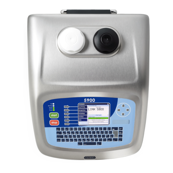
Linx 5900 How To Use Manual
Hide thumbs
Also See for 5900:
- Manual (557 pages) ,
- Quick start manual (81 pages) ,
- How to use manual (13 pages)
Table of Contents
Advertisement
Advertisement
Table of Contents

Subscribe to Our Youtube Channel
Related Manuals for Linx 5900


Summary of Contents for Linx 5900
- Page 1 How To Use the Parallel I/O Option...
-
Page 2: Table Of Contents
How To Use the Parallel I/O Option Contents 1 Introduction........................... 2 1.1 Health and Safety ........................2 2 About the Parallel I/O option ....................... 3 2.1 Applications ..........................3 2.2 Components ........................... 3 2.2.1 PCB layout........................4 2.3 Optional accessories ......................5 2.3.1 Keypad option......................... -
Page 3: Introduction
1.1 Health and Safety Make sure that you read and understand the Health and Safety information in the ‘Safety’ section of the Linx 5900 & 7900 Quick Start Guide. Page 2 of 33 FA69388–2 English... -
Page 4: About The Parallel I/O Option
How To Use the Parallel I/O Option 2 About the Parallel I/O option The Parallel I/O (Parallel Input/Output) option allows a remote host device (PLC or computer) to control the printer or to monitor the printer status. The Parallel I/O unit has eight inputs and eight outputs. -
Page 5: Pcb Layout
How To Use the Parallel I/O Option 2.2.1 PCB layout CAUTION: Static-Sensitive Devices. The PCB contains static-sensitive devices. Take the following antistatic precautions when PCBs are touched. Wear an antistatic wrist strap and connect the lead to a good electrical earth. Always hold PCBs by their edges and do not touch the components, printed circuit tracks or connector pins. -
Page 6: Optional Accessories
2.3.2 Multi-stage alarm option The standard 5900 and 7900 printers have one alarm output. The Parallel I/O option allows the printer to generate four separate alarm outputs. If the multi-stage alarm option is fitted, you can use the four outputs to indicate four different alarm conditions. The alarm outputs are connected to a special socket at the rear of the printer cabinet. -
Page 7: Configure A Keypad
How To Use the Parallel I/O Option 2.4.1 Configure a keypad You can use the PIO option to connect a keypad. The keypad uses some or all of the inputs and outputs. The following example shows a keypad that is connected to some inputs (A) and some outputs (B). - Page 8 How To Use the Parallel I/O Option To configure the software, perform the following steps: Select the Keypads option to display the Edit Keypads page. 69424 Figure 5. Edit Keypads page Press the New key and enter the keypad name “LKP07070”, as shown in the example in Figure 6.
- Page 9 How To Use the Parallel I/O Option Press the OK key to return to the Edit Keypads page. The page displays the keypad name that you entered. 69427 Figure 7. Edit Keypads page You can use the New key to add an additional keypad if some inputs and outputs are available.
- Page 10 How To Use the Parallel I/O Option To change the setting, highlight the required button, and then press the Edit key to display the Edit Action page. 69428 Figure 9. Edit Action page Press the Select key to display the list of actions. 69429 Figure 10.
- Page 11 How To Use the Parallel I/O Option Highlight the required action, and then press the OK key to assign that action to the keypad button. If you use the ‘Select Message’ action, the printer displays an additional page, as shown below. 69430 Figure 11.
- Page 12 How To Use the Parallel I/O Option There is an equivalent page for the ‘Set Remote Field’ action. 69432 Figure 13. Edit Action page: Select Remote Field Use this page to set the Remote Field Name option to the name of the remote field that you created in the message.
-
Page 13: Configure The Inputs
How To Use the Parallel I/O Option 2.4.2 Configure the inputs Set the links LK2 to LK5 to the default position (A), so that the printer provides the 0 V and 24 V connections. Refer to ‘Input connections’ on page 29 for information about the input wiring. - Page 14 How To Use the Parallel I/O Option Select the First Input option to display the First Input page. Highlight the number ‘6’ as shown below. 69436 Figure 17. First Input page Press the OK key to return to the New Input page. The First Input option is changed to 6.
- Page 15 How To Use the Parallel I/O Option Press the OK key to return to the New Input page. The Last Input option is changed to 4. 69439 Figure 20. New Input page Press the Exit key to return to the Edit Inputs page. The page shows you the range of inputs that you assigned.
- Page 16 How To Use the Parallel I/O Option To configure another input or another range of inputs, press the New key, and then repeat steps 2 to 7. If you configure more inputs, the inputs that you assigned earlier (6 to 4) are not available in the First Input or Last Input pages. 69441 Figure 22.
- Page 17 How To Use the Parallel I/O Option To configure the inputs, perform the following steps. At the Edit Inputs page (see Figure 21 on page 14), press the Edit Action key to display the following page. 69442 Figure 23. Edit Inputs page: input actions The number of items in this list depends on the number of inputs that you assigned to this range.
- Page 18 How To Use the Parallel I/O Option Select the required action (see steps 5 to 10 on page 9 to page 11). 69444 Figure 25. Edit Inputs page: select action Do one of the following: • Select another combination of input states from the list. •...
- Page 19 How To Use the Parallel I/O Option Press the Select key to display the Detection page. 69446 Figure 27. Detection page The following table shows the detection options that are available. The table also shows the event that makes the printer detect a change in the state of the input line. Detection option Detection event Latch on Board One...
- Page 20 How To Use the Parallel I/O Option If you use the After Inputs are Steady option, the Edit Detection page has an additional option. 69461 Figure 28. Edit Detection page Set the Steady Time option as required to define the minimum period. You can set the value to 10, 50, or 100 milliseconds.
- Page 21 How To Use the Parallel I/O Option Press the Exit key to return to the Edit Inputs page. 69459 Figure 30. Edit Inputs page The page shows the range of inputs that you use for the numeric remote field. Press the Edit Action key to display the Numeric Remote Field page. 69460 Figure 31.
-
Page 22: Configure The Outputs
How To Use the Parallel I/O Option 2.4.3 Configure the outputs You can use any output to indicate an event that you define (if the output is not assigned to a keypad). The outputs are used separately, and are not assigned to any range. Event At the Parallel I/O page, select the Outputs option to display the Edit Outputs page. - Page 23 How To Use the Parallel I/O Option Highlight one of the events in the list, and then press the OK key to select that event and return to the Event page. 69449 Figure 34. Edit Outputs: Outputs page In Figure 34, Output 1 is activated if the printer status is “IDLE”. Duration The output signal can be a single pulse, a series of pulses, or a continuous level.
- Page 24 How To Use the Parallel I/O Option Highlight the required type, and then press the OK key to return to the Duration page. If you selected the Pulsed option, the page shows two more options— Duration and Pulse Count. 69451 Figure 36.
-
Page 25: Configure The Multi-Stage Alarm
How To Use the Parallel I/O Option 2.4.4 Configure the multi-stage alarm (Refer to the Linx 7900 Maintenance Manual for information about the hardware connections.) Perform the following steps to configure the multi-stage alarm. At the Parallel I/O page, select the Alarm Outputs option to display the following page. - Page 26 How To Use the Parallel I/O Option To change a setting, highlight one of the items in the list and press the Yes key: 69454 Figure 39. Alarm Outputs page The key label changes to ‘No’. If you press the key again, the setting changes to ‘No’ and the key label changes to ‘Yes’.
-
Page 27: Parallel I/O Runs
How To Use the Parallel I/O Option 2.4.5 Parallel I/O Runs This option on the Parallel I/O page tells the printer when to enable, or to disable, the Parallel I/O unit. Select the Parallel I/O Runs option to display the following page. 69455 Figure 40. -
Page 28: Hardware
How To Use the Parallel I/O Option 2.4.6 Hardware Use the Hardware page to configure the inputs and outputs to match the electrical characteristics of the external signals. 69456 Figure 41. Hardware page Input Inversion Select the Input Inversion option to configure the inputs to match the polarity of the input signals. - Page 29 How To Use the Parallel I/O Option Input Sink You can connect two types of input signal: Sink Use this setting for an active low input. Source Use this setting for an active high input. Refer to ‘Input connections’ on page 29 for more information. To configure the Input Sink options, perform the following steps.
-
Page 30: Links And Connections
How To Use the Parallel I/O Option 3 Links and Connections 3.1 Link positions The following illustration shows the positions of the links on the PIO option PCB. 73058 Figure 44. Link Positions Link LK1 is not described in this document. Make sure that this link is in position 0 before the PCB is fitted into the printer. -
Page 31: Output Connections
How To Use the Parallel I/O Option If the ‘Source’ option is selected, connect any inputs that are not active to the 0 V line. To connect an active input, use a pull-down resistor on the input (A) as shown in Figure 46 (a), or use a relay (b). -
Page 32: Parallel I/O Connector
How To Use the Parallel I/O Option 3.4 Parallel I/O connector The Parallel I/O connector is a 25-way D-type connector on the rear panel of the printer (see Figure 48 on page 32). 3.4.1 Pin numbers The function of each connector pin is shown in the following table. PARALLEL I/O CONNECTIONS Pin no. - Page 33 How To Use the Parallel I/O Option Figure 48 shows the pin numbers for the connector. 69463 Figure 48. 25-way Parallel I/O connector Page 32 of 33 FA69388–2 English Jun 2013...
-
Page 34: Multi-Stage Alarm Connectors
How To Use the Parallel I/O Option 3.5 Multi-stage alarm connectors The multi-stage alarm can use either a six-pin volt-free contact (VFC) connector or seven-pin 24 V connector for outputs. The function of the connector pins for each connector is shown in the following diagrams. 69391 MULTI-STAGE ALARM (VFC) CONNECTOR Signal...
Need help?
Do you have a question about the 5900 and is the answer not in the manual?
Questions and answers