Air Lift AirLift 1000 Manual
Hide thumbs
Also See for AirLift 1000:
- Installation manual ,
- Installation instructions manual (10 pages) ,
- Instructions manual (6 pages)
Table of Contents
Advertisement
Quick Links
1989 AND OLDER VEHICLES
Air line must be
routed next to
Rib Bolt
tab to prevent
pinching
Lower Spring
Retainer
FRONT
Figure 1
1990 AND NEWER VEHICLES
Air line must be
Rib Bolt
routed next to
tab to prevent
pinching
Lower Spring Retainer
Isolator Bushing
FRONT
Figure 2
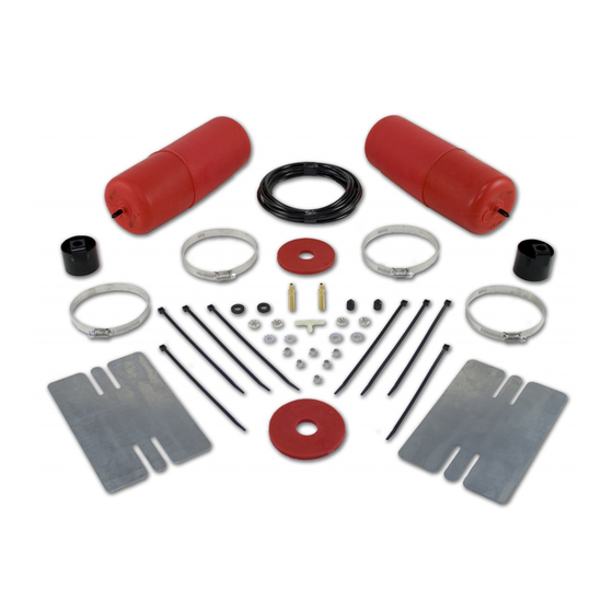
P/N 60738
Air Cylinder
Lower Protector
Tab
Cylinder
Support
FRONT
Cylinder support must be
positioned with tab towards
front of vehicle.
Spring Retainer Nut
Air
Cylinder
Lower Protector
Tab
Cylinder
Support
FRONT
Cylinder support must be
positioned with tab towards
front of vehicle.
"Finger"
Trimmed Off
Spring Retainer Nut
BY
1. Raise vehicle on hoist or jack. Position jack stands
under outside frame rails, one on each side at the
rear of axle. Remove rear tires, lower jack or hoist to
engage frame stands and unload coil spring.
(If necessary, additional clearance between the
spring coils may be obtained by removing the lower
shock absorber attachment).
2. Observe the lower spring retainer orientation so it can
be reinstalled in the same location.
3. Loosen and remove the lower spring retainer nut.
Remove the retainer from the spring.
4. Loosely-assemble the spring retainer nut to the
shoulder bolt. Turn spring retainer upside down, so
that the nut is up, tap the nut with a hammer to
remove the rib bolt. Disassemble nut from rib bolt
(Figure 1 and 2).
5. Position rib bolt through the cylinder support (Figure 1
and 2) and seat bolt shoulder to cylinder support tab
with a hammer and drift pin (If a vise is not available
use a deep well socket).
6. LATE MODELS-Under the lower spring retainer will
be a rubber bushing. It will be necessary to trim one
of the "fingers" of the large rubber bushing in order to
gain clearance for the line (Figure 3).
7. Reinstall the lower spring retainer to its original
orientation. Position the cylinder support shoulder
bolt through the spring retainer (and rubber bushing is
it applies) and the lower control arm holes (Figure 1
and 2). NOTE: Cylinder support tab must be forward
(Figure 1) and spring retainer must be oriented
correctly. LATE MODELS-Cylinder support may not
sit flat on the rubber bushing, may sit on an angle,
this is acceptable.
8. It will be necessary to use channel locks to hold the
lower cylinder support while tightening the nut to the
manufactures spec. (41-65 FT-LBS).
9. Air cylinders are shipped in the "as molded" shape.
For ease of installation remove plastic cap from
barbed stem on end of cylinder. Push on air cylinder
to evacuate as much as possible. It may be rolled up
toward valve stem. Replace cap on stem to maintain
flat shape.
MN-158
(11706)
ECR 6162
Advertisement
Table of Contents

Related Manuals for Air Lift AirLift 1000


Summary of Contents for Air Lift AirLift 1000
- Page 1 MN-158 (11706) ECR 6162 P/N 60738 1. Raise vehicle on hoist or jack. Position jack stands 1989 AND OLDER VEHICLES under outside frame rails, one on each side at the rear of axle. Remove rear tires, lower jack or hoist to engage frame stands and unload coil spring.
- Page 2 10.Insert flattened air cylinder into lowest opening in the coil spring with stem at the bottom (Figure 4). 11. Push the cylinder up within the coil by hand or with a BLUNT instrument such as a spoon-type CUT/TRIM OFF tire iron (Figure 4). When the cylinder is completely within the coil, remove the cap and allow the cylinder to assume it’s “as molded”...
- Page 3 27.Recheck air pressure after 24 hours. A 2-4 psi Inflation loss after initial installation is normal. If pressure Valve has dropped more than 5 lbs. re-test for leaks with soapy water solution. Lock Washer Rubber Thank you for purchasing Air Lift products Washer Hex Nut Figure 7...
- Page 4 Always add air to springs in small quantities, checking the pressure frequently. Air springs require less air volume than a tire and inflate quickly. Thank you for purchasing Air Lift Products AIR LIFT COMPANY P.O. BOX 80167...
- Page 5 No. Adding air springs will not change the weight ratings (GAWR, GCWR and/or GVWR) of a vehicle. Exceeding the GVWR is dangerous and voids the Air Lift warranty. Q. Is it necessary to keep air in the air springs at all time and how much pressure will they need? The minimum air pressure should be maintained at all times.
- Page 6 The consumer is responsible for installation/reinstallation (labor charges) of the product. Air Lift Company reserves the right to change the design of any product without assuming any obligation to modify any product previously manufactured.
Need help?
Do you have a question about the AirLift 1000 and is the answer not in the manual?
Questions and answers