Table of Contents
Advertisement
Quick Links
Advertisement
Table of Contents

Related Manuals for FLIR Thermal MSX Videoscope Kit


Summary of Contents for FLIR Thermal MSX Videoscope Kit
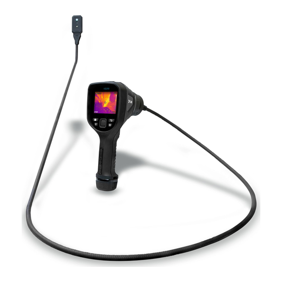
- Page 1 USER MANUAL Thermal MSX ® Videoscope Kit Kit no. VS290–32...
- Page 3 USER MANUAL Thermal MSX® Videoscope #NAS100060; r. AA/71942/71942; en-US...
- Page 5 The documentation must not, in whole or part, be copied, photocopied, repro- duced, translated or transmitted to any electronic medium or machine-read- able form without prior consent, in writing, from FLIR Systems. Names and marks appearing on the products herein are either registered trademarks or trademarks of FLIR Systems and/or its subsidiaries.
- Page 6 • Battery charger (two bays) • AC power supply • USB-C cable • SD card • Software: License card for ‘FLIR Thermal Studio Standard’, 1 Year Subscription • Wrist strap • Hard-shell carry-case for all items • Printed Quick Start and Warranty documentation...
-
Page 7: Extended Warranty
Otherwise, the standard one-year warranty will be in effect from date of purchase. The 2–10 warranty covers parts and labour for the camera for 2 years and coverage of the detector for 10 years. Register your product at https://support.flir.com/prodreg. #NAS100060; r. AA/71942/71942; en-US... - Page 8 • Before operating the device, you must read, understand, and follow all in- structions, dangers, warnings, cautions, and notes. • FLIR Systems reserves the right to discontinue models, parts or accesso- ries, and other items, or to change specifications at any time without prior notice.
- Page 9 Safety WARNING FCC Warnings. Applicability: Class B digital devices. This equipment has been tested and found to comply with the limits for a Class B digital device, pursuant to Part 15 of the FCC Rules. These limits are designed to provide reason- able protection against harmful interference in a residential installation.
-
Page 10: Product Description
Product Description 4.1 Videoscope Base Unit Description Figure 4.1 Base Unit Description 1. Camera display 2. Image and video Gallery button 3. LED worklight button 4. Navigation Pad. Menu button (centre) and navigation buttons (outer ring) 5. Return button (exit a menu) 6. - Page 11 Product Description 4.2 Control Buttons The four control buttons and navigation pad are explained below. 4.2.1 Power Button Long press the power button to switch the instrument ON or OFF. 4.2.2 Return Button Press the Return button to exit or move backward in the programming menu. 4.2.3 Gallery Button Press the Gallery button to access the stored images and video.
- Page 12 Product Description 4.3 Top Compartment Ope the top flap to access the USB connector and the SD card slot. Figure 4.3 Accessing the USB connector and SD card in the top compartment. 4.4 Rectangular Probe (VSC-IR32) Figure 4.4 Camera lenses and worklight. 1.
- Page 13 Product Description 4.5 Display Description Figure 4.5 Videoscope display. 1. Battery status 2. USB active 3. Worklight active 4. Cross-hairs. Target a surface spot to measure its temperature. See Sec- tion 7.6, Measurements Menu, for additional cross-hairs functionality. 5. Highest temperature sensed in the current camera image. 6.
-
Page 14: Battery Charging And Use
Battery Charging and Use The VS290–32 kit is supplied with two high capacity batteries and a stand- alone two-bay charger. To charge batteries, place them in the charger and plug the charger into an AC receptacle. The LED indicators on the charger flash while a battery is charging and glow steadily when fully charged. - Page 15 Battery Charging and Use Figure 5.2 Installing and removing a battery. #NAS100060; r. AA/71942/71942; en-US...
-
Page 16: Quick Steps
Quick Steps These steps are provided to provide a simple overview. Please read the entire User Manual before putting these devices into professional operation. 1. Insert a fully charged battery into the VS290 handle. 2. Long press the power button to power up. - Page 17 Quick Steps 5. To select an image mode, press the Menu button (centre), scroll to the Im- age Mode icon and press Menu again. Use the navigation buttons to se- lect Thermal MSX, Thermal, or Digital camera; press Menu to confirm. 6.
-
Page 18: Programming Menus
Programming Menus 7.1 Basic Navigation Press the Menu button (centre) to open the main menu and the sub-menus. Use the navigation buttons to scroll left/right and up/down. Use the Menu but- ton (centre) to confirm a selection; press the Return button to exit a menu. - Page 19 Programming Menus 7.4 Image Mode Menu Figure 7.3 Accessing the Image Mode menu. Press Menu on the Image Mode icon and use the navigation buttons to select: Digital, Thermal, Thermal MSX, or Alignment Distance. Thermal MSX (Multi-Spectral Dynamic Imaging) is an enhancement that im- proves image clarity by embossing visual scene details on the thermal image, providing added context to accurately target potential issues.
- Page 20 Programming Menus 7.5 Color Palette Menu Figure 7.6 Accessing the Color Palette mode. To select a display color palette, press Menu on the Color icon and use the navigation arrows to scroll. Press Menu when the desired color palette is selected (Iron, Rainbow, Gray, Above Alarm, or Below Alarm).
- Page 21 Programming Menus Figure 7.8 Isotherm Alarm examples. 7.6 Measurements Menu Figure 7.9 Accessing the Measurements mode menu. Navigate to the Measurement icon and press Menu. Select from the available options, detailed below, and then press Menu to confirm. • Centre Spot .
- Page 22 Programming Menus Figure 7.10 Select a measurement type. Centre Spot for manual targeting (temperature dis- played on upper left corner of display); Hot Spot for automatic targeting of hottest spot in the target rectangle; Cold Spot for automatically targeting coldest spot in the rectangle; No Meas- urements for removing the temperature display digits.
-
Page 23: Settings Menu
Programming Menus Figure 7.12 Image on left shows Auto mode where the temperature range uses all of the available spectrum. Image on right shows the Lock mode where the temperature range can be constrained. To constrain the range, point to a spot in the frame that represents the tem- perature of interest, and then select the Lock mode. - Page 24 Programming Menus Figure 7.14 Select Video or Single shot (still image) mode. When the trigger is pulled, a vid- eo or a photo will be stored, depending on the selection made here. 7.9.2 Measurement Parameters Sub-Menu Figure 7.15 Accessing the Measurement Parameters menu. Press Menu on the Settings icon and press Menu again at the Measurement Parameters sub-menu.
- Page 25 Programming Menus Figure 7.16 Selecting an emissivity preset or a customer setting. • Scroll to the Reflected Temperature option, press Menu, and set a reflected temperature value. Figure 7.17 Setting the Reflected Temperature value using the up/down arrow buttons. • Scroll to the Atmospheric Temperature option, press Menu, and set an at- mospheric temperature value.
- Page 26 Programming Menus 7.9.3 Save Options Sub-Menu Press Menu on the Settings icon and press Menu again at the Save Options sub-menu. When set to ON, the camera stores two images (thermal and digi- tal) for each Thermal MSX image captured. Use the navigation buttons to set on/off and press Menu to confirm.
- Page 27 Programming Menus Figure 7.21 Selecting the user interface Language. Figure 7.22 Selecting the Temperature Units. #NAS100060; r. AA/71942/71942; en-US...
- Page 28 Programming Menus Figure 7.23 Setting the Date, Time, and Format. • Set individual Auto Power Off (APO) timers for the camera and the worklight. Figure 7.24 Setting the APO time for the main unit and the worklight. • Adjust the screen and worklight brightness. #NAS100060;...
- Page 29 Programming Menus Figure 7.25 Set the display and worklight brightness. • View system information including serial number and firmware version. Figure 7.26 View the System Information. • Revert to factory default conditions and format memory card. #NAS100060; r. AA/71942/71942; en-US...
- Page 30 Programming Menus Figure 7.27 Reset the unit to factory default conditions. • View regulatory data. Figure 7.28 Accessing the Regulatory compliance information. #NAS100060; r. AA/71942/71942; en-US...
-
Page 31: Taking Measurements
Taking Measurements NOTE Before proceeding to put the VS290 into professional operation ensure that all system, safety, and programming information is well understood as explained in this operation manual. 8.1 Charge and Install the Battery As discussed in Section 5, Battery Charging, place the batteries in the sup- plied bay charger. - Page 32 Taking Measurements 8.4 Positioning the Probe into the Test area 1. Carefully position the probe into the area to be examined, as shown in ac- companying figure. Figure 8.1 Inserting the probe into the test area. 2. View the image for the area you are inspecting. Figure 8.2 View the test area on the VS290 display.
- Page 33 Taking Measurements 6. To capture an image or to stop/start a video, pull and hold the trigger. Press the Gallery button to view stored images and videos. Images/vid- eos can be transported to a PC via USB. #NAS100060; r. AA/71942/71942; en-US...
- Page 34 Isothermal Color (Above and Below) Alarms 9.1 Isotherms Overview Isotherm Alarms allow you to set a high and/or low temperature set point. The image colorings show the areas that exceed the set point temperatures. To configure the Isotherms, open the Color menu and select the desired alarm mode.
- Page 35 Working with Images and Video 10.1 SD Card Slot The SD Card slot is located inside the VS290 top compartment. See illustra- tion below. Do not remove or insert an SD Card with the camera powered up. Do not use an SD Card that has been formatted by another camera as the file structure system may differ.
- Page 36 Working with Images and Video Figure 10.2 Pull and hold the trigger to capture an image or start a video. Images and videos are stored on the memory card (supplied) inserted in the VS290 top compartment. Do not insert or remove the memory card while the VS290 is powered.
- Page 37 Working with Images and Video Figure 10.3 The VS290 must be disconnected from the PC, otherwise the error message shown will appear when you attempt to capture an image. #NAS100060; r. AA/71942/71942; en-US...
- Page 38 MSX® Imaging Technology MSX (Multi-Spectral Dynamic Imaging) extracts scene details from the built-in visual camera and embosses them onto the full thermal image. This allows you to see the thermal image in context of the environment you are viewing. The added context assists in accurately targeting potential problems in electri- cal, mechanical, and building applications.
-
Page 39: Specifications
Specifications IMAGING AND OPTICAL SPECIFICATIONS IR Resolution 160 x 120 pixels Digital image enhancement Thermal sensitivity /NETD < 100 mK 57° x 44° Field of View (FOV) Minimum focus distance 5.9 in. (0.15 m) Image frequency 8.7 Hz IMAGE PRESENTATION Display resolution 320 x 240 pixels Screen size... -
Page 40: Data Communication
Specifications Worklight type Bright LED DATA COMMUNICATION USB Type-C (data transfer/power) ADDITIONAL DATA Battery type Rechargeable 3.7 V Lithium ion Battery operating time > 5 hours (full display brightness and work- light ON) Weight Complete kit with case: 28.7 lbs. (13 kg) Display: 1.41 lbs. -
Page 41: Customer Support
CUSTOMER SUPPORT Customer Support Telephone List: https://support.flir.com/contact Repair, Calibration, and Technical Support https://support.flir.com #NAS100060; r. AA/71942/71942; en-US... - Page 42 #NAS100060; r. AA/71942/71942; en-US...
- Page 44 Customer support http://support.flir.com Copyright © 2020, FLIR Systems, Inc. All rights reserved worldwide. Disclaimer Specifications subject to change without further notice. Models and accessories subject to regional market considerations. License procedures may apply. Products described herein may be subject to US Export Regulations.
Need help?
Do you have a question about the Thermal MSX Videoscope Kit and is the answer not in the manual?
Questions and answers