Table of Contents
Advertisement
Quick Links
INSTALLATION MANUAL
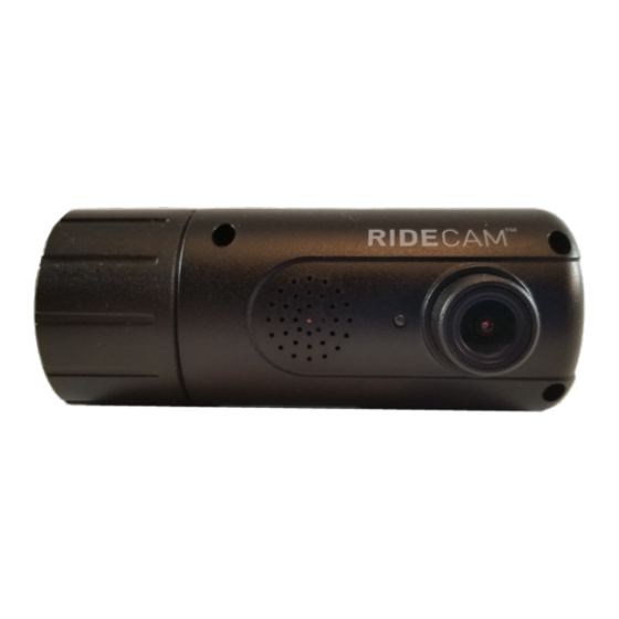
CameraView (Front Facing Camera)
Document ID: IM-DC-X1
Last Updated: March 24, 2021
Pedigree Technologies recommends using a professional installer for optimal
results. Please let your Pedigree Technologies representative suggest a provider if
you need help with your hardware installations.
PedigreeTechnologies.com | Support: (701)-499-0022
Advertisement
Table of Contents

Related Manuals for Pedigree Technologies OneView CameraView


Summary of Contents for Pedigree Technologies OneView CameraView
- Page 1 CameraView (Front Facing Camera) Document ID: IM-DC-X1 Last Updated: March 24, 2021 Pedigree Technologies recommends using a professional installer for optimal results. Please let your Pedigree Technologies representative suggest a provider if you need help with your hardware installations. PedigreeTechnologies.com | Support: (701)-499-0022...
-
Page 2: Required Information
• The field of view should not have too much “sky”. • Split windows may have to adjust mounting location other than what is recommended in this document. Consult with your implementation manager at Pedigree Technologies. PedigreeTechnologies.com | Support: (701)-499-0022... -
Page 3: Power Cable
CameraView Front Facing Installation Steps, Continued Dry Fit Determine proper placement of camera on the front windshield. (Dry fit only. It’s important to run cabling to power source and determine where it will fit properly.) • High on the windshield behind the rearview mirror area or right of center divider (slightly to the passenger side) •... - Page 4 CameraView Front Facing Installation Steps, Continued Standard Direct Wire Installation STEP ONE Connect the ground (black) wire of the direct wire harness to DC chassis ground. • It may be necessary to crimp a ring terminal to the ground wire. •...
- Page 5 CameraView Front Facing Alternative Option - APMM Power Module Installation for Cab-Mate One STEP ONE Identify and record the ESN of the Cab-Mate One before proceeding. The following steps will cover the serial number and you will need it for activating the device later, or servicing the device in the future.
- Page 6 CameraView Front Facing Alternative - APMM Power Module Installation for Cab-Mate One continued STEP FIVE Secure the APMM bracket to the Cab-Mate One by sandwiching it between the Cab-Mate One and the ball mount using the supplied screw and washer pack. (Use the longer machine screws provided, paired with star washers.) Ball Mount APMM Bracket...
- Page 7 CameraView Front Facing Alternative - APMM Power Module Installation for Cab-Mate One continued STEP EIGHT Connect the APMM harness to the AUX1 and LMU DIAG ports on the top of the APMM module. Top view STEP NINE Mount the Cab-Mate One/APMM assembly to the dash using the Panavise ball mount (not pictured).
- Page 8 CameraView Front Facing Alternative Option - APMM Power Module Installation for CalAmp LMU 3640 STEP ONE For a previously installed LMU 3640, unplug the diagnostic cable from the LMU. Remove Existing Diagnostic Cable STEP TWO Plug the longer 16-pin plug from the APMM harness into the 16 pin port on the LMU, replacing the diagnostic cable you just removed if working on previously installed LMU.
- Page 9 CameraView Front Facing Alternative APMM Power Module Installation - CalAmp LMU 3640 continued... Power Module STEP FOUR Plug the 16 pin plug from the short end of the APMM harness into the LMU DIAG port on the power module. STEP FIVE Plug the 6 pin plug from the APMM harness into the AUX 1 port on the power module.
- Page 10 CameraView Front Facing Test Camera Functionality STEP ONE Start the truck’s engine. STEP TWO Make sure that the camera has power (indicated by the blue LED next to the camera lens, may take 30-45 seconds to receive power). Blue LED next to camera lens STEP THREE On the tablet, open POV, but stay logged out.
-
Page 11: Mount Camera
CameraView Front Facing Installation Steps, Continued Mount Camera STEP ONE Determine proper placement of camera on the front windshield. • Center of the windshield behind the rearview mirror area • Highest possible placement within the wiper blade path • Avoid any overhanging exterior sun visor or other materials on glass including rock chips or cracks. -
Page 12: Secure The Camera
CameraView Front Facing Secure the Camera STEP ONE Place the tamper tape across the camera and the mount (where the camera rotates) to secure the camera position. (Avoid covering the camera vents or serial number tag.) Tape the inline cable to the camera mount to prevent removal of the cable.
Need help?
Do you have a question about the OneView CameraView and is the answer not in the manual?
Questions and answers