Advertisement
Quick Links
INSTALLATION MANUAL
CameraView (Mitac Camera)
Document ID: IM-DC-X4
Last Updated: April 21, 2022
Pedigree Technologies recommends using a professional installer for optimal
results. Please let your Pedigree Technologies representative suggest a provider if
you need help with your hardware installations.
PedigreeTechnologies.com | Support: (701)-499-0022
Advertisement

Related Manuals for Pedigree Technologies CameraView jC400


Summary of Contents for Pedigree Technologies CameraView jC400
- Page 1 CameraView (Mitac Camera) Document ID: IM-DC-X4 Last Updated: April 21, 2022 Pedigree Technologies recommends using a professional installer for optimal results. Please let your Pedigree Technologies representative suggest a provider if you need help with your hardware installations. PedigreeTechnologies.com | Support: (701)-499-0022...
- Page 2 • The field of view should not have too much “sky”. • Split windows may have to adjust mounting location other than what is recommended in this document. Consult with your implementation manager at Pedigree Technologies. PedigreeTechnologies.com | Support: (701)-499-0022...
-
Page 3: Power Cable
CameraView JC400 Installation Steps, Continued Dry Fit Determine proper placement of camera on the front windshield. (Dry fit only. It’s important to run cabling to power source and determine where it will fit properly.) • High on the windshield next to the rearview mirror area right of center divider •... - Page 4 CameraView Mitac APMM Power Module Installation for Cab-Mate One Installation of new Cab-Mate One plus camera - Start with Step One Installation of camera on previously installed Cab-Mate One - Start with Step Three - 2 Installation of new camera on Cab-Mate One with previously installed camera (switching out cameras) - Start with Step Eleven STEP ONE...
- Page 5 CameraView Mitac APMM Power Module Installation for Cab-Mate One continued STEP FIVE Secure the APMM bracket to the Cab-Mate One by sandwiching it between the Cab-Mate One and the ball mount using the supplied screw and washer pack. (Use the longer machine screws provided, paired with star washers.) Ball Mount APMM Bracket...
- Page 6 CameraView Mitac APMM Power Module Installation for Cab-Mate One continued STEP EIGHT Connect the APMM harness to the AUX1 and LMU DIAG ports on the top of the APMM module. Top view STEP NINE Mount the Cab-Mate One/APMM assembly to the dash using the Panavise ball mount (not pictured).
- Page 7 CameraView Mitac APMM Power Module Installation for CalAmp LMU 3640 STEP ONE For a previously installed LMU 3640, unplug the diagnostic cable from the LMU. Remove Existing Diagnostic Cable STEP TWO Plug the longer 16-pin plug from the APMM harness into the 16 pin port on the LMU, replacing the diagnostic cable you just removed if working on previously installed LMU.
- Page 8 CameraView Mitac APMM Power Module Installation - CalAmp LMU 3640 continued... Power Module STEP FOUR Plug the 16 pin plug from the short end of the APMM harness into the LMU DIAG port on the power module. STEP FIVE Plug the 6 pin plug from the APMM harness into the AUX 1 port on the power module.
- Page 9 CameraView Mitac Direct Wire Installation Option STEP ONE Cut off the 10-pin molex connector from the power cable. STEP TWO The Black wire (ground) should be securely fastened to a grounded screw or chassis ground. STEP THREE The Yellow wire (power) should be connected to a constant 12-24VDC power source found at the key source or the fuse panel.
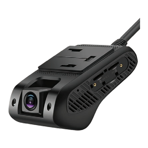
- Page 10 CameraView Mitac Installation Steps, Continued Connect Power Cable to Camera STEP ONE Connect the power plug to the power port on the camera. Camera with power cable attached Power Cable Port Test Camera Functionality STEP ONE Blue Power LED Before securing cabling, check that the camera is receiving power.
-
Page 11: Mount Camera
CameraView Mitac Installation Steps, Continued Mount Camera STEP ONE Determine proper placement of camera on the front windshield. • Center of the windshield next to the rearview mirror area • Highest possible placement within the wiper blade path • Avoid any overhanging exterior sun visor or other materials on glass including rock chips or cracks. - Page 12 CameraView Mitac Mount Camera continued STEP FIVE Orient the camera to the windshield. • Camera should be level to the horizon line. • Point the lens forward with a slight downward angle so the camera picks up the front hood at the bottom of the frame.
-
Page 13: Mounting Tips
CameraView Mitac Mounting Tips GOOD MOUNTING TIPS • Metrics visual detection happens within red square area (image right) • Horizon line must be level with more road than sky • Field of view in green area • No occulsions in field of vision. Good = level horizon, road in range Bad = too much sky CABIN VIEW...
Need help?
Do you have a question about the CameraView jC400 and is the answer not in the manual?
Questions and answers