Table of Contents
Advertisement
Quick Links
Via Acquanera, 29
22100 Como
tel. 031.526.566 (r.a.) fax 031.507.984
info@calpower.it
www.calpower.it
PN 3952199
November 2010
© 2010 Fluke Corporation. All rights reserved. Printed in USA. Specifications are subject to change without notice.
All product names are trademarks of their respective companies.
RUSKA 7615
Hydraulic Pressure Controller/Calibrator
Users Manual
Advertisement
Table of Contents

Related Manuals for Fluke Calibration RUSKA 7615


Summary of Contents for Fluke Calibration RUSKA 7615
- Page 1 Via Acquanera, 29 22100 Como tel. 031.526.566 (r.a.) fax 031.507.984 info@calpower.it www.calpower.it RUSKA 7615 Hydraulic Pressure Controller/Calibrator Users Manual PN 3952199 November 2010 © 2010 Fluke Corporation. All rights reserved. Printed in USA. Specifications are subject to change without notice.
- Page 2 LIMITED WARRANTY AND LIMITATION OF LIABILITY Each Fluke product is warranted to be free from defects in material and workmanship under normal use and service. The warranty period is one year and begins on the date of shipment. Parts, product repairs, and services are warranted for 90 days.
-
Page 3: Table Of Contents
Table of Contents Chapter Title Page General Information ................1-1 Introduction......................1-1 General Information................... 1-1 How to Contact Fluke ..................1-1 Safety Information ..................... 1-2 Safety Summary .................... 1-2 Keep Away From Live Circuits..............1-2 Do Not Service or Adjust Alone..............1-2 Resuscitation.................... - Page 4 RUSKA 7615 Users Manual The Power Supply....................2-1 The Electronics Module..................2-1 The Back Plane....................2-1 The Microprocessor Board ................2-1 The Analog / Digital I/O Board..............2-2 The IEEE-488 Interface................. 2-2 The Front Panel ..................... 2-2 The Control Board..................2-2 The Hydraulic/Pneumatic Module..............
- Page 5 Contents (continued) Programming Sequences..................4-7 Storing a Sequence in Memory ..............4-7 Preparing to Program..................4-7 Program name ................... 4-7 Configuration .................... 4-7 Number of Set-Points................4-7 Set Point Pressure and Tolerance .............. 4-8 Dwell time....................4-8 Max time ....................4-8 Mode of entry....................
- Page 6 RUSKA 7615 Users Manual Zeroing ......................6-8 Cleaning ......................6-8 Preparation for Storage & Shipment ..........7-1 Disconnecting the Calibrator ................7-1 Packing Instructions................... 7-1 Shipping Instructions ..................7-2 Appendices A Summary of Specifications ................. A-1 B Summary of Error Messages ............... B-1...
- Page 7 List of Tables Table Title Page 1-1. Symbols........................1-3 1-2. 7615 DPC Options List ..................1-5 2-1. Conversion Factors....................2-3 3-1. General Specifications & Parameters..............3-2 5-1. RS-232 Pin Allocations..................5-2...
- Page 8 RUSKA 7615 Users Manual...
- Page 9 List of Figures Figure Title Page 2-1. DPC Block Diagram ....................2-2 2-2. RUSKA 7615 Calibrator Hydraulic/Pneumatic Diagram ........2-4 4-1. RUSKA 7615 Front Panel..................4-1 4-2. Menu Tree ......................4-2...
- Page 10 RUSKA 7615 Users Manual viii...
-
Page 11: General Information
This section of the manual provides general information about the Calibrator and presents its features and options. General Information The RUSKA 7615 Calibrator uses transducers to provide the precise measurement of pressure. During normal operation, the Calibrator performs in either Measure Mode or Control Mode. -
Page 12: Safety Information
RUSKA 7615 Users Manual Safety Information Safety Summary The following are general safety precautions that are not related to any specific procedures and do not appear elsewhere in this publication. These are recommended precautions that personnel must understand and apply during equipment operation and maintenance to ensure safety and health and protection of property. -
Page 13: Symbols Used In This Manual
European safety directives. The equipment carries the CE mark. Features The following features are standard on all RUSKA 7615 Calibrators. NIST Traceability All Calibrator’s are calibrated using RUSKA deadweight gages, which are directly traceable to the National Institute of Standards and Technology (NIST). All instruments are provided with a NVLAP accredited calibration certificate. -
Page 14: Friendly Display
RUSKA 7615 Users Manual Friendly Display The Calibrator’s vacuum fluorescent display combines a bright, low-glare readout with a wide viewing angle. During normal operation, the measured pressure is easily visible from a distance of 10 feet (3 meters). Adjustable Pressure Display The pressure display can be adjusted to show one decimal greater than or less than the default resolution. -
Page 15: Standard Equipment & Options
General Information Standard Equipment & Options Standard Equipment & Options A standard hydraulic Calibrator comes with this manual, and a power cord. The standard hydraulic Calibrator is fully functional, but the following options are also available. Additional Power Cords: Additional power cords are available for most countries of the world. - Page 16 RUSKA 7615 Users Manual...
-
Page 17: Theory Of Operation
Chapter 2 Theory of Operation Introduction The Calibrator’s power supply, electronics, pneumatics, hydraulics, and sensor combine to form a complete, stand-alone, measure and control instrument. This portion of the manual breaks the Calibrator down into its component modules (See Figure 2-1) and provides a general discussion of each. -
Page 18: The Analog / Digital I/O Board
RUSKA 7615 Users Manual The Analog / Digital I/O Board The Calibrator’s Analog/Digital I/O board, which plugs directly into the back plane, is utilized by the Calibrator to read various analog and digital signals and to drive system solenoids. The IEEE-488 Interface The Calibrator’s IEEE-488 (GPIB) Interface card, which plugs directly into the Back... -
Page 19: The Hydraulic/Pneumatic Module
Theory of Operation The Hydraulic/Pneumatic Module Table 2-1. Conversion Factors Symbol Description Conversion Factor inHg inches of mercury (0°C) = kPa x 0.2952998 inHg inches of mercury (60°C) = kPa x 0.296134 kiloPascals = kPa x 1.0 bars = kPa x 0.01 pounds per inch 2 = kPa x 0.1450377 centimeters of water (4°C) -
Page 20: Reservoir Valve
RUSKA 7615 Users Manual gko002.bmp Figure 2-2. RUSKA 7615 Calibrator Hydraulic/Pneumatic Diagram Reservoir Valve The reservoir valve isolates the pump from the reservoir. It is a high pressure valve actuated by a pneumatic dome valve. This pneumatic dome valve has a diaphragm operator which is driven be an internally regulated 80 psi air pressure which is sourced from the air supply port. -
Page 21: Fluid Reservoir
Theory of Operation The Hydraulic/Pneumatic Module Fluid Reservoir The reservoir supplies system fluid to the pump through the reservoir valve. The reservoir has a 1000 cc capacity and is provided with a low level sensor. System Valve The system valve isolates pump from the system. It is a high pressure valve actuated by a pneumatic dome valve. - Page 22 RUSKA 7615 Users Manual...
-
Page 23: Installation
Installation Introduction This portion of the manual discusses initial installation for the RUSKA 7615 Calibrator. Installing the Calibrator is a relatively simple process of unpacking the Calibrator, powering it up, and then using the front panel to configure the system. -
Page 24: Cautions
RUSKA 7615 Users Manual Table 3-1. General Specifications & Parameters Parameter Value Model Operating Humidity Range 5% to 95% RH None 1 Storage Humidity Range Operating Temperature 5 °C to 50 °C Storage Temperature -20 °C to 70 °C Air Supply –... -
Page 25: Hydraulic/Pneumatic Connections
Installation Hydraulic/Pneumatic Connections Hydraulic/Pneumatic Connections Pneumatic connection to the Calibrator is straightforward. The following sections discuss each port. Air Supply Port The supply port must be connected to a well regulated source of dry shop air. Air supply should be regulated between 100 to 110 psi. Supply port is a ¼ tube connection. The air supply source should be capable of provide a peak flow rate of 150 Standard Liters per Minute (300 SCFH). -
Page 26: Tutorial
RUSKA 7615 Users Manual 4. Another method to fill or purge the device under test is to use the system’s “purge fill” option. To use this option, from the front panel main menu press MENU, TEST, PURGE and FILL PUMP. Enter the number of Fill Cycles (Charge/discharge) you would like to run. - Page 27 Installation Tutorial 3. Press Units (the F3 key). This will display the Menu/Setup/Units screen. The list of available units will be displayed with the current units highlighted. º 4 º mmHg cmH20 user1 feet º 4 º CmHg inH20 user2 meters º...
- Page 28 RUSKA 7615 Users Manual 12. After the pressure is stabilized press the Step ↑ or Step ↓ key. The scratchpad will be updated with a new set-point. The step size defaults to 10% of full scale. (The step size is set to other values in the MENU/SETUP/LIMITS screen.) 13.
-
Page 29: Local Operation
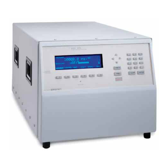
The keys are separated according to their function. gko009.eps Figure 4-1. RUSKA 7615 Front Panel Numeric Keypad This includes the numeric digits, the decimal point, and the change sign key. The CLEAR key will clear the numeric entry field. -
Page 30: Cancel, Prev, Abort
RUSKA 7615 Users Manual Cancel, Prev, Abort These keys are used to stop, undo, or exit the current operation. The CANCEL key will return all edited fields on the current entry screen to their original values. It will also stop the current program sequence or calibration process. -
Page 31: Measuring Pressure
Menu Multi-Range Sensor - Options The RUSKA 7615 Calibrators are available as multi-range instruments. The number of sensors available in an instrument can range from one to six. To select an active range, from the main menu, select the MENU/MODE keys. The F5 function key is labeled as “range”, and by depressing the F5 key, the system will cycle between the various... -
Page 32: Defining A New Pressure Unit
RUSKA 7615 Users Manual Defining a New Pressure Unit In addition to the standard units of measure provided by the Calibrator, four user-defined units are available. To create one of these units, the user enters a name that is one to six characters long and a conversion factor that is a multiple of kiloPascals (kPa). -
Page 33: Using Head Pressure Correction
Local Operation Controlling Pressure Using Head Pressure Correction The term head height refers to the vertical distance between the sensing element in the device under test and the Calibrator’s sensor. Once the user inputs the head height and specific gravity of fluid used the Calibrator automatically corrects for head pressure. 1. -
Page 34: Cycle Modes
RUSKA 7615 Users Manual Cycle Modes This mode of operation offers the fastest method of generating cyclic pressures and is ideal for fatigue testing and extended proof pressure cycling. Initially the 7615 controls to the maximum pressure. The pneumatic/hydraulic intensifier is then isolated from the system and then driven to the end of its travel. -
Page 35: Stepping And Jogging
Local Operation Programming Sequences Stepping and Jogging In addition to entering a new value, the pressure set-point may also be changed by user-definable steps and by jogging small amounts. From the Main Menu (press PREV until the Main Menu appears) press Step ↑ [F4] to add the step amount to the current set-point. -
Page 36: Set Point Pressure And Tolerance
RUSKA 7615 Users Manual Set Point Pressure and Tolerance Each set point in the program requires both a pressure and a tolerance, in the current units of measure. For example, one set-point might require a tolerance as low as 0.5 (min control) psi, whereas another set-point in the same program could be satisfied with a tolerance as high as 5 psi. -
Page 37: Automatically Generating A Program
Local Operation Programming Sequences 7. Repeat steps 5 and 6 until the test sequence is complete. 8. When all steps have been entered, press PREV to return to the Named programs screen. Automatically Generating a Program In order for the Calibrator to automatically generate a program the user must input the first set-point pressure, the last set-point pressure, and the number of steps in between, as well as the dwell time, max time and tolerance common to all setpoints. -
Page 38: Changing The Configuration Stored With A Program
RUSKA 7615 Users Manual 3. Press Edit [F4]. The program editing screen will appear, displaying the first step. 4. The Next [F1] and Prev [F2] keys may be used to move through the program. To go directly to a specific step use the Arrow keys to highlight go to step, use the numeric keypad to enter the step number and press ENTER. -
Page 39: Configuration
Local Operation Configuration 5. To pause the program press Pause [F3]. Pause will now be highlighted and the Calibrator will continue controlling to the current setpoint. Press Cont [F4] to resume the program. 6. To stop the program press Stop [F5]. The program will stop running but the Calibrator will continue controlling to the current setpoint. - Page 40 RUSKA 7615 Users Manual 4-12...
-
Page 41: Remote Operation
Chapter 5 Remote Operation Remote Operation The Calibrator can be operated remotely by a computer. Two standard interfaces are supported: IEEE-488, and RS-232. Both interfaces support SCPI (Standard Commands for Programmable Instruments). The IEEE-488 interface additionally supports emulation of a RUSKA Single Channel Interface Panel (Models 6005-701 and 6005-761). The IEEE-488 interface conforms to the following standards. -
Page 42: Remote/Local Operation
RUSKA 7615 Users Manual RS-232 The RS232 interface supports standard serial operation from a computer to a single Calibrator. RS232 supports the IEEE-488.2 and SCPI commands. The Calibrator allows the following port setups. Baud Rate: 1200, 2400, 9600, or 19200... -
Page 43: Configuration
Remote Operation Configuration Configuration The remote interface is configured using the local interface before the remote is connected. The parameters needed varies with the interface used. IEEE-488 Address, Protocol RS-232 Baud Rate, Data Bits, Parity, Stop Bits To configure the remote interface follow these steps: 1. -
Page 44: Ansi/Ieee 488.2-1987 Command Summary
RUSKA 7615 Users Manual ANSI/IEEE 488.2-1987 Command Summary *CLS Clear Status *ESE? Event Status Enable Query *ESE <number> Event Status Enable *ESR? Event Status Register *IDN? Identification *OPC? Operation Complete Query (Returns 1) *OPC Operation Complete *RST Reset *SRE? Service Request Enable Query *SRE <number>... - Page 45 Remote Operation Device Messages :MODE MEASure¦CONTrol¦VENT sets mode :MODE? returns mode string PROGram :CATalog? returns list of defined programs [SELected] :DEFine <program block> Define program press1, toler1, dwell1, max1, press2, toler2, :DEFine? read program definition :DELete [:SELected] deletes current program :ALL deletes all programs :NAME <program name>...
-
Page 46: Example Scpi Commands
RUSKA 7615 Users Manual :DEFine<n> <name>,<number> define a unit :LENGth MM|IN set length units for head height [:PRESsure] <unit name> set pressure units Example SCPI Commands To request the current pressure reading all of the following commands are equivalent: :MEASURE:PRESSURE? -
Page 47: Interface Panel Emulation
Remote Operation Interface Panel Emulation Bit 14 Program Running. Bit 15 0. Questionable Status (QUES:EVENT, QUES:CONDITION, QUES:ENABLE) Bit 0 Voltage is questionable. Set when supply voltages are not within 5%. Bit 1 Current is questionable. Always 0. Bit 2 Time is questionable. Set when the clock has not been set. Bit 3. - Page 48 RUSKA 7615 Users Manual...
-
Page 49: Maintenance
Chapter 6 Maintenance Introduction Very little maintenance is normally required for the Calibrator. The following sections discuss some of the suggested procedures. Observing the Calibrator’s Full Scale Rating Instructions for observing the Calibrator’s full scale rating are given below. 1. If necessary, press PREV several times to return the display to the Main screen. 2. -
Page 50: Processor Battery
RUSKA 7615 Users Manual WX Warning The Calibrator should only be opened by qualified electrical/mechanical service technicians. Lethal voltages are present and exposed in the power supply and display. 1. Turn off the Calibrator and disconnect the power cord from the power supply. -
Page 51: Calibration Instructions-Single And Dual Sensor
Calibration Calibration Instructions—Single and Dual Sensor To calibrate the RUSKA 7615, the user simply connects a calibration standard to the RUSKA 7615’s Test Port then follows the 4-step calibration procedure on the Calibrator’s display. On dual sensor versions, the operator would be instructed to select one of the two sensors to be calibrated. -
Page 52: Storing The Coefficients
RUSKA 7615 Users Manual 2. When the Measured pressure stabilizes, use the 7615’s numeric keypad and OK to enter the actual pressure applied by the calibration standard. Do not enter the Measured pressure reported by the Calibrator. If necessary, use the CLEAR key to correct a mistake in the edit field. -
Page 53: Calibration Instructions-Multi-Ranged Sensor
Calibration Instructions—Multi-Ranged Sensor To calibrate the RUSKA 7615, the user simply connects a calibration standard to the Calibrator’s Test Port then follows the 4-step calibration procedure on the Calibrator’s display. Optional pressure ranges are available with the 7615 provided up to six ranges in a single instrument. - Page 54 RUSKA 7615 Users Manual Step 1 1. To begin Step 1 of the calibration process, select ZERO. Enter the actual pressure applied and press ok. a. Wait until the zero procedure completes. This may take several minutes. When the Calibrator completes Step 1, the Calibrator will request which sub-range of the triple range sensor is to be calibrated.
-
Page 55: Storing The Coefficients
Maintenance Calibration Note If the actual pressure applied is outside of the tolerance for the requested high-point pressure, Error—222 Data out of range will occur. Acknowledge this error by selecting OK, then re-enter the actual pressure, repeating Step 3, number 1, if necessary Step 4 1. -
Page 56: Zeroing
RUSKA 7615 Users Manual Note To exit the calibration procedure before the calibration coefficients have been changed, press CANCEL any time during the procedure. 4. Select the range to be edited. 5. Use the arrow keys to highlight the coefficient to be edited. -
Page 57: Preparation For Storage & Shipment
The main principle behind a successful shipment is that of minimizing shocks. This is accomplished by cradling the device within two boxes such that the RUSKA 7615 is restrained but still has resilience. The two most successful materials for this purpose are rubber foam and flexible polyurethane foams. -
Page 58: Shipping Instructions
In general, prepare the Calibrator for shipment as follows: 1. Fluke Calibration has an RMA procedure in place. Please contact the Customer Service Center to obtain an RMA number prior to returning any equipment to Fluke. -
Page 59: A Summary Of Specifications
Appendix A Summary of Specifications Accuracy Specifications of pressure transducer instrumentation can be divided into three categories: Input Specifications, General Specifications, and Performance Specifications. Each of these categories in turn consists of parameters which are usually specified by minimum and/or maximum numeric limits. Almost all of these parameters can have an effect on what is generally referred to as the instrument’s “accuracy.”... - Page 60 RUSKA 7615 Users Manual The key to eliminating an error is knowing its source and type along with its polarity and magnitude. Generally, the source is simple to detect and is represented by the specific parameter. The type is usually a function of the instrument’s design and manufacturing process.
- Page 61 Summary of Specifications Specifications Cycle Control Mode: Setup time to reach initial pressure <30 seconds Operating time to full pressure: <10 seconds (4 seconds typical) Operating time to Min pressure: <10 seconds (7 seconds typical) Time to complete one full cycle: <20 seconds (11 seconds typical) Overpressure Protection: Relief valves and rupture disk set at 110% FS Pressure port: Test port: Autoclave F250C...
- Page 62 RUSKA 7615 Users Manual...
-
Page 63: B Summary Of Error Messages
Appendix B Summary of Error Messages Summary of Error Messages Negative error numbers are from the Standard Commands for Programmable Instruments (Version 1991.0). Table B-1. Error Messages Value Description and Corrective Action No Error. -103 Invalid Separator. Check punctuation in the SCPI command. -104 Data Type. - Page 64 RUSKA 7615 Users Manual Table B-2. Error Messages, continued. Value Description and Corrective Action -313 Configuration Data Lost. The configuration data has been lost and the unit must be recalibrated. -315 Configuration Data Lost. The configuration data has been lost. Check all parameters to be sure they are correct.
Need help?
Do you have a question about the RUSKA 7615 and is the answer not in the manual?
Questions and answers