Table of Contents
Advertisement
Quick Links
Advertisement
Table of Contents

Related Manuals for Fluke Calibration 525B/A0 120V


Summary of Contents for Fluke Calibration 525B/A0 120V
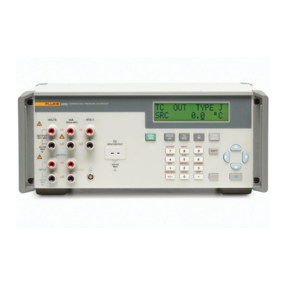
- Page 1 525B Temperature/Pressure Calibrator Users Manual July 2012 © 2012 Fluke Corporation, All rights reserved. All product names are trademarks of their respective companies. MyFlukeStore 1.800.561.8187 www. Shop for Fluke products online at:...
- Page 2 LIMITED WARRANTY AND LIMITATION OF LIABILITY Each Fluke product is warranted to be free from defects in material and workmanship under normal use and service. The warranty period is one year and begins on the date of shipment. Parts, product repairs, and services are warranted for 90 days.
-
Page 3: Table Of Contents
Table of Contents Chapter Title Page 1 Getting Started ................... 1-1 Introduction ...................... 1-1 Contacting Fluke ....................1-1 Standard Equipment ..................1-2 Options and Accessories .................. 1-2 Safety Information ................... 1-2 Getting Acquainted with the Calibrator ............1-5 Input and Output Terminals ..............1-5 Using the Keys .................. - Page 4 525B Users Manual Thermocouple Zero Calibration ............3-4 Measuring Temperature Using Resistance Temperature Detectors (RTDs) ..................3-5 Entering and Using Custom RTDs ............3-7 Default RTD Coefficients ................. 3-8 Entering Custom SPRT Coefficients ............3-9 Measuring Pressure ................... 3-10 4 Remote Operation ................
- Page 5 Contents (continued) Programming the STB and SRE ............4-24 Event Status Register (ESR) ..............4-24 Event Status Enable (ESE) Register ............. 4-24 Bit Assignments for the ESR and ESE ..........4-25 Programming the ESR and ESE ............4-26 Output Queue .................... 4-26 Error Queue ....................
- Page 6 525B Users Manual DC Current Specifications, Output ............7-2 Resistance Specifications, Output ............. 7-3 Resistance Specifications, Input ............... 7-3 Thermocouple Specification, Output and Input ........7-4 RTD and Thermistor Specification, Output ..........7-5 RTD and Thermistor Specification, Input ..........7-6 Pressure Measurement ..................
- Page 7 List of Tables Table Title Page 1-1. Summary of Input and Output Functions............1-2 1-2. Symbols Used on the Calibrator ..............1-4 1-3. Pushbutton Usage Functions ................1-7 1-4. Function Keys ....................1-8 1-5. Display Error Messages ................... 1-10 2-1. Default RTD Coefficients ................
- Page 8 List of Figures Figure Title Page 1-1. Input and Output Terminals and Connectors ........... 1-5 1-2. Pushbuttons ...................... 1-6 1-3. Calibrator Function Keys ................. 1-8 1-4. Rear Panel View ....................1-11 2-1. Connection to Simulate Thermocouple Temperature ........2-2 2-2. Connection to Simulate a RTD Temperature ...........
-
Page 9: Getting Started
Chapter 1 Getting Started Introduction Your Fluke 525B Temperature/Pressure Calibrator (referred to as the Calibrator) is an instrument designed to meet the demands of your process tools calibration workload. In addition to the functions in Table 1-1, the Calibrator has the following features and functions. -
Page 10: Standard Equipment
525B Users Manual Table 1-1. Summary of Input and Output Functions Function Input Output dc V None 0 V to 100 V dc mA None 0 to 100 mA 0 to 4000 Ω (4-wire) 5 to 4000 Ω (2-wire) Resistance Thermocouple Pressure Standard Equipment... - Page 11 Getting Started Safety Information A Warning statement identifies hazardous conditions and actions that could cause bodily harm or death. A Caution statement identifies conditions and actions that could damage the Calibrator or the equipment under test. International symbols used on the Calibrator and in this manual are explained in Table 1-2.
- Page 12 525B Users Manual Table 1-2. Symbols Used on the Calibrator Earth ground AC (Alternating Current) Resistance DC (Direct Current) Conforms to European Union Pressure directives Canadian Standards Association, Chassis protective ground NRTL ...
-
Page 13: Getting Acquainted With The Calibrator
Getting Started Getting Acquainted with the Calibrator Getting Acquainted with the Calibrator Input and Output Terminals Figure 1-1 shows the Calibrator input and output terminals and explains their use. VOLTS 100mA MAX OUTPUT STBY VOLTS TYPE 100V MAX UNITS INPUT/OUTPUT 20V PK OUTPUT INPUT... -
Page 14: Using The Keys
525B Users Manual Using the Keys Figure 1-2 shows the Calibrator pushbuttons and Table 1-3 explains their use. Other function keys are shown in Figure 1-3 and described in Table 1-4. VOLTS TYPE STBY UNITS OUTPUT INPUT ZERO SHIFT SETUP C / F RECALL AUTOSET... - Page 15 Getting Started Getting Acquainted with the Calibrator Table 1-3. Pushbutton Usage No Name Description Cycles the Calibrator through Standby and Operate modes. Toggles between DC voltage and DC current modes. Toggles between the current thermocouple and current ...
-
Page 16: Calibrator Function Keys
525B Users Manual STBY VOLTS TYPE UNITS OUTPUT INPUT ZERO SHIFT SETUP C / F RECALL AUTOSET RNG LOCK LOCAL • ENTER fcn11f.eps Figure 1-3. Calibrator Function Keys Table 1-4. Function Keys No Name Description RNG LOCK Activates/deactivates the autorange feature of the Calibrator in ... - Page 17 Getting Started Getting Acquainted with the Calibrator Table 1-4. Function Keys (cont) No Name Description SETUP Press to advance through the LCD Backlight, Interface, and Address menus. • Use and to adjust LCD backlight when the LCD menu is displayed.
-
Page 18: Display Error Messages
525B Users Manual Table 1-4. Function Keys (cont) No Name Description RECALL Used to recall a programmed set point. Press . RECALL SPT # appears on the display. Enter the number of the output setpoint that you want to use. The output will then be programmed to the setpoint you entered. -
Page 19: Rear Panel View
Getting Started Getting Acquainted with the Calibrator Rear Panel View Figure 1-4 shows the features on the rear panel of the Calibrator and explains their use. NO INTERNAL USER SERVICEABLE PARTS REFER SERVICE TO QUALIFIED SERVICE PERSONNEL FLUKE CORPORATION MADE IN USA WARNING: PATENTS PENDING FOR FIRE PROTECTION... -
Page 20: Using Output Mode
Chapter 2 Using Output Mode Using Output Mode In Output mode, the Calibrator generates calibrated signals for testing and calibrating process instruments. In Output mode, the Calibrator: • supplies voltage, current, and resistance • simulates the output of RTD and TC temperature sensors Note message displays if you enter an invalid output OVER RANGE... -
Page 21: Simulating Thermocouple Temperature
525B Users Manual Simulating Thermocouple Temperature Connect the Calibrator TC input/output to the unit under test (UUT) with thermocouple wire and the appropriate thermocouple mini-connector. Supported TC types are listed in Chapter 7. Figure 2-1 shows this connection. To simulate temperature using a thermocouple (TC): 1. -
Page 22: Simulating Temperature Using Resistance Temperature Detectors (Rtds)
Using Output Mode Using Output Mode Simulating Temperature Using Resistance Temperature Detectors (RTDs) RTDs have a characteristic resistance at specific temperatures. The simulated output, then, is a resistance value based on the selected temperature and type of RTD being simulated. To simulate temperature using a resistance temperature detector: 1. -
Page 23: Simulating Custom Rtd Coefficients
525B Users Manual Simulating Custom RTD Coefficients The USR_DEF RTD type allows the Calibrator to simulate a custom curve-fit RTD. To enter the coefficients for a custom RTD: 1. Press to select RTD mode. 2. Press until you get the display. -
Page 24: Default Rtd Coefficients
Using Output Mode Using Output Mode Default RTD Coefficients The USR_DEF function of the calibrator uses the Calendar-Van Dusen equation for outputting and measuring custom RTDs. The C coefficient is only used for the subrange –260 to 0 degrees Celsius. Only the A and B coefficients are needed for the subrange 0 to 630 degrees. -
Page 25: Entering Custom Standard Platinum Resistance Thermometer (Sprt) Coefficients
525B Users Manual Entering Custom Standard Platinum Resistance Thermometer (SPRT) Coefficients To enter coefficients for a custom SPRT: 1. Press to enter RTD mode. 2. Press until you get the display and press . RTD SPRT and press . 3. -
Page 26: Output Dc Voltage
Using Output Mode Using Output Mode Output DC Voltage The Calibrator is a fully programmable precision source of DC voltage from 0 V to 100 V. The Calibrator can only output positive (+) values. To output DC voltage: 1. Connect the Calibrator to the UUT as shown in Figure 2-3. 2. -
Page 27: Output Resistance
525B Users Manual Output Resistance To output resistance: 1. Connect the Calibrator to the UUT as shown in Figure 2-4. 2. Press until RTD mode is selected. 3. If necessary, press for RTD OUT mode. 4. Press to select the appropriate ohms output range (400 or 4000 ohms). 5. -
Page 28: Output Current
Using Output Mode Output Current Output Current The Calibrator is a fully programmable precision source of DC current from 0 mA to 100 mA. The Calibrator can only output positive (+) values. To output current: 1. Connect the Calibrator to the UUT as shown in Figure 2-5. 2. -
Page 29: Using Input Mode
Chapter 3 Using Input Mode Using Input Mode In Input mode, the Calibrator measures resistance, and temperature from RTD and thermocouple sensors and displays pressure measurements from Fluke 700 and 525A-P series pressure modules. Note The figures in this chapter show how to connect to a Fluke 725 Multifunction Process Calibrator. -
Page 30: Measuring Temperature Using Thermocouples
525B Users Manual MULTIFUNCTION CALIBRATOR VOLTS 100mA MAX V mA ZERO LOOP OUTPUT STBY VOLTS TYPE V mA 100V MAX UNITS MEAS SOURCE TC R ° ° INPUT/OUTPUT OUTPUT INPUT ZERO 20V PK STORE SHIFT 100% SETUP 4W RTD SETUP C / F RECALL RECALL... -
Page 31: Measuring Temperature With A Thermocouple
Using Input Mode Using Input Mode To measure temperature using a thermocouple: 1. Attach the thermocouple leads to the TC input/output connector as shown in Figure 3-2. One pin is wider than the other. Do not attempt to force the plug in the wrong polarization. -
Page 32: Thermocouple Zero Calibration
525B Users Manual Thermocouple Zero Calibration To obtain the optimum measurement accuracy, you must perform a zero calibration when operating the Calibrator outside of the ambient temperature range of 18 ºC to 28 ºC. The zero calibration must be performed with the Calibrator thermally stable at the ambient temperature of operation. -
Page 33: Measuring Temperature Using Resistance Temperature Detectors (Rtds)
Using Input Mode Using Input Mode Measuring Temperature Using Resistance Temperature Detectors (RTDs) You must use a 4-wire connection to achieve the Calibrator accuracy specifications. To measure the RTD output from an instrument: 1. Connect the Calibrator to the instrument you want to measure as shown in Figure 3-3. -
Page 34: Measuring Temperature Using An Rtd Probe
525B Users Manual 4. Press to select the desired RTD type. You can toggle between ºC and ºF temperature units by pressing . VOLTS 100mA MAX OUTPUT VOLTS TYPE STBY 100V MAX UNITS INPUT/OUTPUT 20V PK OUTPUT INPUT ZERO SHIFT 4W RTD... -
Page 35: Entering And Using Custom Rtds
Using Input Mode Using Input Mode Entering and Using Custom RTDs The USR_DEF RTD type allows the Calibrator to simulate a custom curve-fit RTD. To enter the coefficients for custom RTDs: 1. Press to select RTD mode. 2. Press until you get the display. -
Page 36: Default Rtd Coefficients
525B Users Manual Default RTD Coefficients The USR_DEF function of the calibrator uses the Calendar-Van Dusen equation for outputting and measuring custom RTDs. The C coefficient is only used for the subrange –260 to 0 degrees Celsius. Only the A and B coefficients are needed for the subrange 0 to 630 degrees. -
Page 37: Entering Custom Sprt Coefficients
Using Input Mode Using Input Mode Entering Custom SPRT Coefficients To enter coefficients for a custom SPRT: 1. Press to enter RTD mode. 2. If necessary, press for RTD IN mode. 3. Press until you get the display and press . -
Page 38: Measuring Pressure
525B Users Manual Measuring Pressure Many ranges and types of pressure modules are available from Fluke. See “Accessories” in Chapter 6 of this manual for a complete list of supported pressure modules. Before you use a pressure module, read its instruction sheet. Pressure modules vary in use, media, and accuracy. -
Page 39: Remote Operation
(PC) equipped with one or more IEEE- 488 ports. You can write your own computer programs for system operation using the command set, or you can purchase optional Fluke calibration software MET/CAL. Typical IEEE-488 configurations are shown in Figure 4-3. The configuration showing the PC with two IEEE-488 ports is used with MET/CAL, which prefers UUTs on a separate IEEE-488 port. -
Page 40: Setting Up The Rs-232 Port For Remote Control
525B Users Manual Setting up the RS-232 Port for Remote Control The Calibrator is fully programmable over an RS-232 link with a PC. You can enter individual commands from a terminal, write your own programs using, for ® example, a Windows -based language such as Visual Basic, or run optional ®... - Page 41 Remote Operation Setting up the RS-232 Port for Remote Control Complete the following procedure to test RS-232 port operation using the ® Windows HyperTerminal application (or equivalent). To test port operation: 1. Select Start->Programs->Accessories->Hyperterminal->Hyper Terminal. 2. Enter 525B for Name:, and select OK. 3.
-
Page 42: Typical Rs-232 Remote Control Connections
525B Users Manual SERIAL FROM HOST COM Port Port 525B Calibrator Controller System for a UUT without a remote port. SERIAL FROM HOST RS-232 COM Port COM Port Port Port 525B Calibrator Controller System for a UUT with an RS-232 port (via PC). fcn15f.eps Figure 4-2. -
Page 43: Rs-232 Interface Overview
Remote Operation RS-232 Interface Overview RS-232 Interface Overview The Calibrator RS-232 port is designed in accordance with EIA (Electronic Industries Association) standard RS-232-C. RS-232 is a serial binary data interchange operating at 9600 baud and distances up to 50 feet. The Calibrator rear panel serial port is configured as DTE (Data Terminal Equipment). -
Page 44: Typical Ieee-488 Remote Control Connections
525B Users Manual IEEE-488 Port IEEE-488 Port 525B Calibrator Controller System for a UUT without a remote port. 525B Calibrator Controller System for a UUT with an IEEE-488 remote port. RS-232 COM Port Port 525B Calibrator Controller System for a UUT with an RS-232 remote port. fcn13f.eps Figure 4-3. -
Page 45: Ieee-488 Port Setup Procedure
Remote Operation Setting up the IEEE-488 Port for Remote Control IEEE-488 Port Setup Procedure Complete the following procedure to set up the Calibrator for remote operations using the IEEE-488 remote control port. The purpose is to select GPIB as the interface and to select the GPIB address for the interface. -
Page 46: Changing Between Remote And Local Operation
525B Users Manual To test the IEE-488 port: 1. Open the MET/CAL Editor application. 2. Select File->New or press Ctrl+N. 3. Enter IEEE [@4]*IDN?[I$]. If you did not select address 4 in step 6 above, substitute the address you entered for the 4. 4. -
Page 47: Remote With Lockout State
Remote Operation Changing Between Remote and Local Operation Front panel operation is disabled except for the LOCAL (0 key). Pressing 0, using RS-232 to send the command LOCAL, or IEEE-488 to send the GTL (Go To Local) message returns the Calibrator to the local state. Remote with Lockout State When the Calibrator is placed in lockout, either via RS-232 LOCKOUT command, or via the IEEE-488 message LLO, the 525B front panel controls are totally locked... -
Page 48: Ieee-488 Interface Overview
525B Users Manual IEEE-488 Interface Overview The IEEE-488 parallel interface sends commands as data and receives measurements and messages as data. The maximum data exchange rate is 1 Mbyte, with a maximum distance of 20 meters for the sum length of the connecting cables. A single cable should not exceed 4 meters in length. - Page 49 Remote Operation IEEE-488 Interface Overview Type M - Multiline U - Uniline Class AC - Addressed Command DD - Device Dependent AD - Address (Talk or listen) HS - Handshake UC - Universal Command SE - Secondary ST - Status Other B1, B2, etc.
- Page 50 525B Users Manual Table 4-4 IEEE-488 Remote Message Coding (continued) MESSAGE DATA HAND- DESCRIPTION SHAKE MANAGEMENT MESSAGE NAME Parallel Poll Configure M AC Parallel Poll Enable M SE B4 B3 B2 B1 Parallel Poll Disable M SE B4 B3 B2 B1 PPR1 Parallel Poll Response 1 U ST...
-
Page 51: Using Commands
Remote Operation Using Commands Using Commands Communications between the controller and the Calibrator consists of commands, queries, and interface messages. Although the commands are based on the 488.2 standard, they can be used on either the IEEE-488 or RS-232 interface, except for a few specialized RS-232 commands described in “Commands for RS-232 Only.”... -
Page 52: Query Commands
525B Users Manual Query Commands Query commands request information, which is returned as the command executes, or placed in a buffer until requested. An example of a query, which always ends with a question mark, is, RANGE ? returning the Calibrator dc voltage output range. Interface Messages (IEEE-488) Interface messages manage traffic on the IEEE-488 interface bus. - Page 53 Remote Operation Using Commands Table 4-5. IEEE-488 Interface Messages (Received) Mnemonic Name Function Attention A control line that, when asserted, notifies all instruments on the bus that the next data bytes are an interface message. When ATN is low, the next data bytes are interpreted as device-dependent or common commands addressed to a specific instrument.
-
Page 54: Compound Commands
525B Users Manual Table 4-6. IEEE-488 Interface Messages (Sent) Mnemonic Name Function A message that occurs when the 525B asserts the EOI control line. The 525B asserts EOI while it transmits the ASCII character LF for its termination sequence or terminator. -
Page 55: Sequential Commands
Remote Operation Using Commands You can use the command *WAI to wait until the overlapped command has completed execution before executing the next command. For example, OUT 1 V ; *WAI You can also use the status commands *OPC and *OPC? to detect completion of overlapped commands. -
Page 56: Command Syntax
525B Users Manual Command Syntax The following syntax rules apply to all the remote commands. Information about syntax of response messages is also given. Parameter Syntax Rules Table 4-8 lists the units accepted in command parameters and used in responses. All commands and units may be entered in upper or lower case. -
Page 57: Extra Space Or Tab Characters
Remote Operation Using Commands General Rules The general rules for parameter usage is as follows: 1. Numeric parameters may have up 15 significant digits and their exponents can be in the range ± -1.0E ± -20. 2. Including too many or too few parameters causes a command error. 3. -
Page 58: Incoming Character Processing
525B Users Manual IEEE-488 Interface The Calibrator sends the ASCII character Carriage Return with the EOI control line held high as the terminator for response messages. The calibrator recognizes the following as terminators when encountered in incoming data: • ASCII CR character •... -
Page 59: Checking 525B Status
Remote Operation Checking 525B Status Table 4-10. Response Data Types Data Type Description Integer Integers for some controllers or computers are decimal numbers in the range -32768 to 32768. Responses in this range are labeled Integer. *ESE 123; *ESE? Example: Returns: Floating Numbers that may have up to 15 significant figures plus an exponent that may... -
Page 60: Status Register Overview
525B Users Manual Each status register and queue has a summary bit in the Serial Poll Status Byte. Enable registers are used to mask various bits in the status registers and generate summary bits in the Serial Poll Status Byte. For IEEE-488 interface operation, the Service Request Enable Register is used to assert the SRQ control line on detection of any status condition or conditions the programmer chooses. -
Page 61: Serial Poll Status Byte (Stb)
Remote Operation Checking 525B Status Serial Poll Status Byte (STB) The Calibrator sends the serial poll status byte (STB) when it responds to a serial poll. This byte is cleared (set to 0) when the power is turned on. The STB byte is defined as shown in Figure 4-6. -
Page 62: Service Request Enable Register (Sre)
525B Users Manual Service Request Enable Register (SRE) The Service Request Enable Register (SRE) enables or masks the bits of the Serial Poll Status Byte. The SRE is cleared at power up. Refer to Figure 4-6 for the bit functions. Programming the STB and SRE By resetting (to 0) the bits in the SRE, you can mask (disable) associated bits in the serial poll status byte. -
Page 63: Bit Assignments For The Esr And Ese
Remote Operation Checking 525B Status Bit Assignments for the ESR and ESE The bits in the Event Status Register (ESR) and Event Status Enable register (ESE) are assigned as shown in Figure 4-7. Power on. This bit is set to 1 if line power has been turned off and on since the last time the ESR was read. -
Page 64: Programming The Esr And Ese
525B Users Manual Programming the ESR and ESE To read the contents of the ESR, send the remote command, *ESR?. The ESR is cleared (set to 0) every time it is read. To read the contents of the ESE, send the remote command, *ESE?. - Page 65 Remote Operation Checking 525B Status IEEE-488 The Calibrator treats the EOI IEEE-488 control line as a separate data byte and inserts it into the input buffer if it is encountered as part of a message terminator. Input buffer operation is transparent to the program running on the controller.
-
Page 66: Remote Commands
Chapter 5 Remote Commands Introduction Remote commands duplicate activities that can be initiated from the front panel in local operation. Following the summary table is a complete alphabetical listing of all commands complete with protocol details. Separate headings in the alphabetical listing provide the parameters and responses, plus an example for each command. -
Page 67: External Connection Commands
525B Users Manual Common Commands (continued) Command Desc ription *OPT? Returns a list of the installed hardware and software options. *RST Resets the state of the instrument to the power-up state. This command holds off execution of subsequent commands until it is complete. (Overlapped command.) *SRE Loads a byte into the Service Request Enable register (SRE). -
Page 68: Output Commands
Remote Commands Command Summary by Function Output Commands Command Desc ription FUNC? Returns the present output, measurement, or calibration function. OPER Activates the Calibrator output if it is in standby. OPER? Returns the operate/standby setting. Sets the output of the Calibrator. OUT? Returns the output amplitude of the Calibrator. -
Page 69: Status Commands
525B Users Manual Status Commands Command Desc ription FAULT? Returns the latest error code from the error queue, then removes that error code from the queue. Error Code Listing Error Message Number Class Description Error queue overflow. OPER or STBY was received when the 525B is in Measure mode or TC Source mode. -
Page 70: Remote Command Listing
Remote Commands Remote Command Listing Error Code Listing (continued) Error Message Number Class Description An invalid parameter was received. The serial input buffer overflowed. The command string buffer overflowed. The serial output buffer overflowed. The output overloaded. 525B is out of tolerance. This error is set after a failed initialization or a failed *TST?. - Page 71 525B Users Manual *CLS IEEE-488 RS-232 Sequential Overlapped (Clear Status command) Clears the ESR, the error queue, and the RQS bit in the status byte. This command terminates pending operation complete commands (*OPC or *OPC?). Parameter: (None) Example: *CLS Clear the ESR, the error queue, and the RQS bit in the status byte. *ESE IEEE-488 RS-232...
- Page 72 Remote Commands Remote Command Listing *ESR? IEEE-488 RS-232 Sequential Overlapped (Event Status Register query) Returns the contents of the Event Status Register (ESR) and clears the register. (See Event Status Register (ESR)” in Chapter 4.) Response: <value> (decimal equivalent of the ESR byte, 0 to 255) Example: *ESR? returns 189 Returns decimal 189 (binary 00111101) when bits 5 (CME), 4 (EXE), 3 (DDE),...
- Page 73 525B Users Manual Responses: (Indefinite ASCII) A message containing four fields separated by commas as follows: Manufacturer Model number 3. Serial number (always 0) 4. Firmware revision levels for the main, front panel, and inguard CPUs. Example: *IDN? returns FLUKE,525B,0,1.2 Returns Fluke manufacturer, model 525B, serial number 0, firmware version 1.2.
- Page 74 Remote Commands Remote Command Listing Set bit 0 of the Event Status Register to 1 when all pending device operations are done. *OPC? IEEE-488 RS-232 Sequential Overlapped (Operations Complete query) Returns a 1 after all pending operations are complete. This command causes program execution to pause until operations are complete.
- Page 75 525B Users Manual IEEE-488 RS-232 Sequential Overlapped (Output command) Sets the output of the Calibrator and establishes a new reference point for the error mode. To source or measure a temperature, select the desired sensor and sensor parameters first. (See the TSENS_TYPE, RTD_TYPE, and TC_TYPE commands.) Use multipliers, k, m, u with the OUT command, as desired.
- Page 76 Remote Commands Remote Command Listing PRES? IEEE-488 RS-232 Sequential Overlapped (Pressure Module query) Queries the attached pressure module for its model and serial number. Responses: (Indefinite ASCII) A message containing four fields separated by commas as follows: Manufacturer Model number 3.
- Page 77 525B Users Manual PRES_UNIT? IEEE-488 RS-232 Sequential Overlapped (Pressure Units query) Returns the pressure display units. Responses: (pounds per square inch) (inches of water at 4 degrees Celsius) INH2O4C (inches of water at 20 degrees Celsius) INH2O20C (centimeters of water at 4 degrees Celsius) CMH2O4C (centimeters of water at 20 degrees Celsius) CMH2O20C...
- Page 78 Remote Commands Remote Command Listing RANGELCK? IEEE-488 RS-232 Sequential Overlapped (Range command) Returns the RANGELOCK state 1 for ON or 0 for OFF. Parameter: (None) REMOTE IEEE-488 RS-232 Sequential Overlapped (Remote command) Places the Calibrator into the remote state. This command duplicates the IEEE-488 REN (Remote Enable) message.
- Page 79 525B Users Manual RTD_MEAS IEEE-488 RS-232 Sequential Overlapped (RTD Measure command) Selects the measure RTD mode. Parameters: CEL (Celsius) (optional) FAR (Fahrenheit) (optional) Example: RTD_MEAS CEL Measure the RTD temperature that is attached to the Calibrator RTD terminals, in Celsius. RTD_TYPE IEEE-488 RS-232...
- Page 80 Remote Commands Remote Command Listing RTD_TYPE? IEEE-488 RS-232 Sequential Overlapped (Resistance Temperature Detector Type query) Returns the Resistance Temperature Detector (RTD) type used for RTD temperature simulations. Responses: PT385_100 (100-ohm RTD, curve α=0.00385 ohms/ohm/°C) (200-ohm RTD, curve α=0.00385 ohms/ohm/°C) PT385_200 (500-ohm RTD, curve α=0.00385 ohms/ohm/°C) PT385_500 PT385_1000 (1000-ohm RTD, curve α=0.0038 ohms/ohm/°C)
- Page 81 525B Users Manual *SRE? IEEE-488 RS-232 Sequential Overlapped (Service Request Enable query) Returns the byte in the Service Request Enable (SRE). Response: <value> (the decimal equivalent of the SRE byte, 0 to 191) Example: *SRE? returns 48 Returns 48 when bits 4 (MAV), and 5 (ESR) are enabled. *STB? IEEE-488 RS-232...
- Page 82 Remote Commands Remote Command Listing TC_REF IEEE-488 RS-232 Sequential Overlapped (Thermocouple Reference command) Sets whether the internal temperature sensor (INT) or an external reference value (EXT) is used for Thermocouple (TC) outputs and measurements. The Calibrator retains the TC reference setting until power off or reset.
- Page 83 525B Users Manual Z (1 mV/°C linear output) Example: TC_TYPE J Set the thermocouple type for simulating a temperature output to a J-type thermocouple. TC_TYPE? IEEE-488 RS-232 Sequential Overlapped (Thermocouple Type query) Returns the Thermocouple (TC) temperature sensor type. When the thermocouple type is changed while simulating a temperature output, the temperature is changed to 0 °C.
- Page 84 Remote Commands Remote Command Listing TSENS_TYPE? IEEE-488 RS-232 Sequential Overlapped (Temperature Sensor Type query) Returns the temperature sensor type thermocouple (TC) or Resistance Temperature Detector (RTD) for temperature measurements. Responses: TC (Thermocouple) (Resistance Temperature Detector) Example: TSENS_TYPE? returns TC Returns TC when the temperature sensor type is a thermocouple. *TST? IEEE-488 RS-232...
- Page 85 525B Users Manual *WAI IEEE-488 RS-232 Sequential Overlapped (Wait-to-Continue command) Prevents further remote commands from being executed until all previous remote commands have been executed. For example, if you send an OUT command, you can cause the Calibrator to wait until the output has settled before continuing on to the next command if you follow OUT with a *WAI command.
-
Page 86: Maintaining The Calibrator
Chapter 6 Maintaining the Calibrator Maintenance Cleaning the Calibrator Warning To avoid personal injury or damage to the Calibrator, use only the specified replacement parts and do not allow water into the case. Caution To avoid damaging the case, do not use solvents or abrasive cleaners. -
Page 87: Changing Line Voltage
525B Users Manual To check or replace a fuse: 1. Disconnect line power. 2. Using the blade of a standard screwdriver, pry the tab at the base of the line fuse compartment. The compartment cover will pop part way out. 3. -
Page 88: Accessing The Fuse
Maintaining the Calibrator Maintenance 6. Verify you are using the appropriate fuse for the selected line voltage (See Table 6-1) and reinstall the fuse compartment by pushing it in until the tab locks in place. Line voltage indicator Changing line fuse Line fuse compartment Rotate to change... -
Page 89: Performance Tests
525B Users Manual Performance Tests Required Equipment List Table 6-2 lists all the required equipment for performance testing. Table 6-2. Required Equipment Equipment Recommended model Purpose 8-1/2 digit Precision Digital 8508A or Wavetek 1281 DC volts, resistance Multimeter w/option 20 (ohms converter) Resistance standard Fluke 742A-1 DC Current... -
Page 90: Testing Dc Voltage
Maintaining the Calibrator Performance Tests Testing DC Voltage The DC voltage amplitude accuracy test verifies the accuracy of DC voltage at the 525B calibrator front panel Volts Source output. Verify the measurements listed in Table 6-3. Table 6-3. Measuring DC Voltage Nominal Measured 90 Day Spec. -
Page 91: Testing Dc Current
525B Users Manual Testing DC Current Use the 8508A and the precision shunt to measure the 525B output as shown in Figure 6-2. Take the Voltage reading from the 8508A and divide it by the 742A-1 actual value to determine the current output. Verify the measurements listed in Table 6-4. -
Page 92: Testing Thermocouple Output
Maintaining the Calibrator Performance Tests Testing Thermocouple Output For this test, the TC mV specifications will be used. When this test is combined with the CJC test all functions of the TC output will have been checked. Typically, the cable needed to connect the 525B to the 8508A will need to be fabricated. The TC Mini-Connector will need Copper-Copper (White). -
Page 93: Testing Cjc (Cold Junction Compensation)
525B Users Manual Testing CJC (Cold Junction Compensation) Connect a Type-J thermocouple to the TC terminals on the 525B. Immerse the thermocouple and a precision thermometer in a mineral oil lag bath. The test setup is shown in Figure 6-4. Verify that the readings of the 525B and the precision thermometer are within the Type-J specifications: 90-day specification is 0.14 °C... -
Page 94: Testing Thermocouple Input
Maintaining the Calibrator Performance Tests Testing Thermocouple Input Set the 525B to TC input by pressing . All 525B conditions will be the same as the Thermocouple Output test, CJC off, mV/°C mode. Connect the 525B to the 5520A as shown in Figure 6-5. Set the 5520A to the mV values listed in Table 6-5. -
Page 95: Testing Ohms Output
525B Users Manual Testing Ohms Output Use the precision DMM to measure the resistance output as shown in Figure 6-6 and Table 6-6. Note The 8508A must be in the “loI” (low current mode) when measuring 5 ohms in the 4 K ohm range or an overload will occur. VOLTS 100mA MAX OUTPUT... -
Page 96: Testing Ohms Input
Maintaining the Calibrator Performance Tests Testing Ohms Input Before measuring ohms input, you need to “characterize” the ohms output of a 5520A. To achieve the needed accuracy, the 8508A will be used as a transfer standard and the 742A will be used as the reference standard. To find the true value of the 5520A output, use the ratio input function of the 8508A located on the front and rear panels. - Page 97 525B Users Manual Use the 742A-1K for the 400 ohm range. Use the 742A-10K for the 4K ohm range. For more information on the correct usage of ratio mode, refer to the 8508A Operators Manual. Use Table 6-7 to note the ratio indication on the 8508A. Use the formula (742A actual value/ratio indication * 100 = actual 5520A Actual Value column.
-
Page 98: Testing Pressure Modules
Maintaining the Calibrator Performance Tests 525B 525B TEMPERATURE / PRESSURE CALIBRATOR VOLTS 100mA MAX OUTPUT STBY VOLTS TYPE 100V MAX UNITS 5520 4W Ohms INPUT/OUTPUT 20V PK OUTPUT INPUT ZERO SHIFT 4W RTD Function SETUP C / F RECALL AUTOSET 20V PK INPUT SENSE... -
Page 99: Service Center Calibration Or Repair
525B Users Manual Service Center Calibration or Repair Calibration, repairs, or servicing not covered in this manual should be performed only by qualified service personnel. Verify that the Calibrator is being operated in accordance with the instructions in this manual. If the Calibrator is faulty, send a description of the failure with the Calibrator. -
Page 100: Replacement Parts
Maintaining the Calibrator Replacement Parts Replacement Parts Replacement parts are shown in Figure 6-9. Table 6-8 provides a description and part number of each replacement part. fcn20f.eps Figure 6-9. Exploded View of the 525B 6-15 MyFlukeStore 1.800.561.8187 www. Shop for Fluke products online at:... - Page 101 525B Users Manual Table 6-8. Replacement Parts Item Desc ription Part Number Decal, Front Panel 1601576 Fuse Drawer 1617918 Fuse, 0.25 A/250 V (fast for 120 V operation) 1645311 Fuse, 0.125 A/250 V (fast for 240 V operation) 1645327 Output Block 1601601...
-
Page 102: Accessories
Maintaining the Calibrator Accessories Accessories For more information about these accessories and their prices, contact your Fluke representative. Y525 Rack Mount Kit The Y525 rack mount kit provides all the hardware needed to mount the 525B on an equipment rack. Instructions are provided in the kit. 5520A –... - Page 103 525B Users Manual Table 6-8 Fluke 700 Series Pressure Modules (continued) Fluke Model Number Range Type and Media Fluke-700PA4 0 to 15 psi absolute, wet Fluke-700PA5 0 to 30 psi absolute, wet Fluke-700PA6 0 to 100 psi absolute, wet Fluke-700PV3 0 to -5 psi vacuum, dry Fluke-700PV4...
-
Page 104: Specifications
Chapter 7 Specifications General Specifications Warm up time ............Twice the time since last warmed up, to a maximum of 30 minutes. Settling time ............Less than 5 seconds for all functions and ranges except as noted. Standard interface ..........RS-232, IEEE-488 (GPIB) Temperature performance Operating ............ -
Page 105: Electrical Specifications
525B Users Manual Electrical Specifications DC Voltage Specifications, Output Absolute Uncertainty, tcal ± 5 °C Stability ± (ppm of output + µV) Maximum Ranges Resolution Burden 24 hours, ± 1 °C 90 days 1 year ± (ppm of output + µV) 1 µV 0 to 100.000 mV 5 + 2... -
Page 106: Resistance Specifications, Output
Specifications Electrical Specifications Resistance Specifications, Output Absolute Uncertainty tcal ± 5°C, ± Ω Ranges Resolution Allowable Current 90 days 1 year 5 to 400.00 Ω 0.001 Ω 0.012 0.015 1 to 3 mA 0.01 Ω 100 µA to 1 mA 0.25 5 to 4.0000 kΩ... -
Page 107: Thermocouple Specification, Output And Input
525B Users Manual Thermocouple Specification, Output and Input Absolute Uncertainty tcal ± 5 °C, ± (°C) Range (°C) TC Type Output/Input Minimum Maximum 90 days 1 year 600 °C 800 °C 0.42 °C 0.46 °C 800 °C 1000 °C 0.39 °C 0.39 °C 1000 °C 1550 °C... -
Page 108: Rtd And Thermistor Specification, Output
Specifications Electrical Specifications RTD and Thermistor Specification, Output Absolute Uncertainty Range (°C) tcal ± 5 °C, ± (°C) RTD Type Minimum Maximum 90 days 1 year -200 °C -80 °C 0.03 °C 0.04 °C -80 °C 0 °C 0.04 °C 0.05 °C 0 °C 100 °C... -
Page 109: Rtd And Thermistor Specification, Input
525B Users Manual RTD and Thermistor Specification, Output (cont.) Absolute Uncertainty Range (°C) tcal ± 5 °C, ± (°C) RTD Type Minimum Maximum 90 days 1 year Cu 427, 10 Ω -100 °C 260 °C 0.30 °C 0.38 °C 15 °C 50 °C 0.005 °C 0.007 °C... - Page 110 Specifications Electrical Specifications RTD and Thermistor Specification, Input (cont.) Absolute Uncertainty Range (°C) tcal ± 5 °C, ± (°C) RTD Type Minimum Maximum 90 days 1 year -200 °C -80 °C 0.007 °C 0.008 °C -80 °C 0 °C 0.019 °C 0.020 °C 0 °C 100 °C...
-
Page 111: Pressure Measurement
525B Users Manual Pressure Measurement The Calibrator can accept either the Fluke 700 or 525A-P series pressure modules. Pressure modules plug directly into the front panel Lemo connector with the Calibrator firmware autodetecting the type and value of the module you are attaching. Range ........
Need help?
Do you have a question about the 525B/A0 120V and is the answer not in the manual?
Questions and answers