
Subscribe to Our Youtube Channel
Related Manuals for Bernard Controls AQ Logic Series


Summary of Contents for Bernard Controls AQ Logic Series
- Page 1 AQ Logic RANGE Start Up Guide SUG_17004 EN_FR - Instructions de mise en service Ind. A Art :5100577...
- Page 2 TABLE OF LANGUAGES 1 English -------------------------------------------------- 3 2 Français -------------------------------------------------- 3...
-
Page 3: Table Of Contents
TABLE OF CONTENTS SAFETY ---------------------------------------------------------- 5 DELIVERY, STORAGE AND MAINTENANCE ------------------- 5 Delivery Storage Maintenance ACTUATOR INSTALLATION ------------------------------------ 7 Fastening actuator on the valve Opening the control compartment Electrical wiring Closing the control compartment ACTUATOR CONTROLS--------------------------------------- 14 Control panel Control modes Local control with Control panel Local control with Smartphone application Remote control... - Page 4 Set Relays configuration Setting Forced local mode in Remote mode OPERATION --------------------------------------------------- 39 Emergency handwheel operation Local control operation APPENDIX ----------------------------------------------------------- 40 Starting with BC App Alarm and Settings menu tree (options not detailed)
-
Page 5: Safety
English 1 SAFETY This device complies with current applicable safety standards. Installation, maintenance, and use of this unit require a skilled and trained staff. Please carefully read this whole document before mounting and starting-up the actuator. 2 DELIVERY, STORAGE AND MAINTENANCE 2.1 Delivery AQ actuators are delivered in a cardboard box of a size equivalent to the actuator and sit in a cardboard wedge. -
Page 6: Maintenance
English What to check on pre-installed actuators If you expect a long period between actuator mounting and electrical wiring: 4. Visually check that cable entries and cover are tightly closed. 5. In case of outdoor installation, cover the unit with a plastic protective film. -
Page 7: Actuator Installation
English 3 ACTUATOR INSTALLATION 3.1 Fastening actuator on the valve Actuator should be secured directly to the valve using proper bolts or via a proper interface. After assembly, the actuator can operate in any position. You can modify your display orientation in order to keep normal ... - Page 8 English 3.2.1 Changing closing direction indication As a standard, AQ actuator is configured to close clockwise. If the actuator must close counter-clockwise, you can change the orientation of the position indicator cap. This change requires to have the actuator software set ...
-
Page 9: Electrical Wiring
English 3.3 Electrical wiring Ensure wires are not supplied with electric power before wiring is finished and the control compartment is closed. If you need to open control compartment, previously cut off power supply to the actuator. 3.3.1 Components 1 - Position indicator 6 - Torque limiter 2 - Mainboard 7 –... - Page 10 English How to install cable glands For each cable entry used 1. Remove plug from the cable entry with 19mm (M16 entry) or 23mm (M20 entry) open- end wrench. 2. Separate sealing nut from its cable gland. 3. Screw and tighten cable gland in the cable entry.
- Page 11 English Internal ground terminal The ground terminal is a metal tab with a fixation hole located under the terminal board at its bottom left (see following picture). How to wire actuator The wiring must be done according to the wiring diagram of your actuator.
- Page 12 English 3.3.3 Power supply board Power supply board supplies actuator with electrical power. Power characteristics are factory set according to your order. Fuse You have a fuse at the upper left angle of the board (see picture). Its characteristics are the following: Fuse size (mm) 6.3×32 Fuse current...
-
Page 13: Closing The Control Compartment
English 3.3.5 Positioner board (OPTION) Positioner board is assembled on the main board. You can switch between mA and V using the small switch at the base of the board according to your needs. 3.3.6 Heating resistor Each actuator includes a heating resistor. As soon as the actuator is installed in the field, it is recommended to supply the resistor to prevent condensation. -
Page 14: Actuator Controls
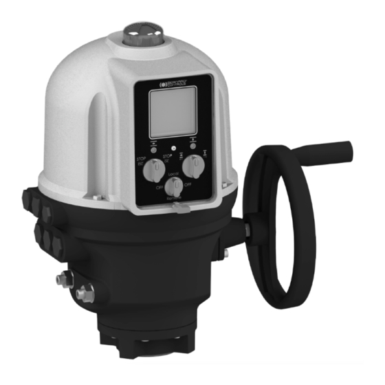
English 4 ACTUATOR CONTROLS 4.1 Control panel Display LED 2 LED 1 Open / close & navigation knob Stopping & validation knob Control mode selector AQ Logic control panel consists of a screen, 2 control knobs, 1 control selector and 2 configurable LEDs. Screen Screen displays operating status or Logic menu Control selector allows to choose the control mode:... -
Page 15: Control Modes
English 4.2 Control modes AQ logic can be controlled locally or remotely. Mode is set using Control selector on the control panel. It can be locked using a padlock located at the bottom of control panel. Modes are : • Local mode with control panel or Smartphone via Bluetooth®... - Page 16 English 4.3.2 Settings Menu screen has 2 main sections… • Alarm and warnings • Settings that allows you to check or change the settings of the actuator: valve tag, password, torque limits, Bluetooth ® , etc. Knobs use Menu navigation ...
-
Page 17: Local Control With Smartphone Application
English 4.4 Local control with Smartphone application Using the Bluetooth® connection of your actuator, you can operate it with Bernard Control smartphone application (BC App). • ® Bluetooth is active on the actuator at delivery • Using the Local control with BC App requires to have Bluetooth® activated on your smartphone You need first to download the application, install it on your phone, then connect to your actuator by entering an access code. - Page 18 English 4.4.2 Main menu You can access the main menu anytime by tapping on From main menu, you can access… • Actuator Operation Diagnostic & status Actuator settings Quit • Account data • Assistance info 4.4.3 Settings screen From the main menu, you can access the settings. Menu screen has 2 main sections…...
-
Page 19: Remote Control
English 4.5 Remote control The AQ Logic remote control system can be operated using an external or an internal voltage supply. The input circuits are fully opto-isolated. The self-hold pulse command system requires 4 connecting wires on the client terminal strip: Common, STOP, OPEN and CLOSE. -
Page 20: Commissionning
English 5 COMMISSIONNING This section describes the commissioning with the Control panel, except otherwise mentioned. You can set the same settings with App from the menu Settings > Commissioning of Actuator on valve. In order to access the actuator settings, control mode must be set to Local mode. - Page 21 English To enter the actuator menu, you need first to enter the access code. If you are the end-user: At the first on-site start, we strongly advise you to modify the default Bluetooth ® access codes. To proceed to these changes, please follow the 2 following procedures.
- Page 22 English How to change the Bluetooth ® access codes with Control panel ® access codes can only be changed using Read & Write Bluetooth mode. 1. Go to Settings > Actuator’s access code. Actuator’s access codes screen appears. 2. Depending on the access code you need to change: •...
- Page 23 English How to change the Bluetooth Access codes with BC App ® 1. Go to Main Menu. 2. Select Settings > Actuator passwords and security. 3. The Actuator passwords & security menu appears. 4. Select the Password you want to change. 5.
-
Page 24: Set Closing Rotation Direction
English 5.2 Set closing rotation direction Default setting for closing direction is clockwise. According to your needs, you may have to change your closing direction. How to change closing direction 1. Enter the menu, then go to Settings > Actuator commissioning >... -
Page 25: Set Closing And Opening On Torque Or Position
English 5.3 Set closing and opening on torque or position This section allows you to define the way you want to stop actuator travel in both directions. You can choose either Position or Torque. How to set opening and closing type of end of travel Settings Actuator 1. - Page 26 English How to set torque limits 1. Enter the menu, then go to Settings > Commissioning. 2. Select Set torque limits and validate with OK. 3. Select closing or opening direction and validate with OK. Torque limits screen appears. then validate with OK.
- Page 27 English 5. To set Break limits • To set No limit, use on 1 digit, then ESC. • To set another value, validate 1 digit with OK then validate each with OK. then set 2 & 3 with ...
-
Page 28: Setting Open And Closed Positions
English 5.5 Setting open and closed positions 5.5.1 Setting end positions AQ Logic features position sensor. To set end positions, you have first to record OPEN and CLOSED positions one after the other, depending on the first one set. Mechanical stops must not be used as travel limits. - Page 29 English If your valve still cannot reach closed position, reset the closing mechanical stop (see §5.5.2) and resume this whole procedure. 4. Validate Confirm with OK. The setting screen for the opposite setting appears. 5. Open your valve using the opening knob An indication of stroke angle appears.
- Page 30 English If you reach the opening mechanical stop before valve is open, reset the opening mechanical stop. 6. Validate Confirm with OK. Closing and opening positions are set. Once end positions are set, proceed to an operation in each direction to check the settings.
- Page 31 English How to adjust mechanical stops for both directions Clockwise mechanical stop setting 1. Untighten the nut corresponding to clockwise mechanical stop and turn the mechanical stop 2 turns back. 2. Drive the actuator to clockwise travel limit position. 3. Get the clockwise mechanical stop in contact with output sleeve then turn it back of 1 turn.
-
Page 32: Set Display Orientation
English 5.6 Set display orientation Your display orientation can be modified according to the physical orientation of your actuator. How to change orientation of your display 1. Enter the menu, then go to Settings > Buttons & Display. The following screen appears. 2. -
Page 33: Set Leds Configuration
English 5.7 Set LEDs configuration Your LEDs configuration can be adjusted according to the standard of your country. How to set LEDs configuration 1. Enter the menu, then go to Settings > Buttons & Display. The Buttons & Display screen appears. Go down in the menu to LED color. - Page 34 English 5.8 Set Relays configuration Available relays can be configured for specific functions. How to set Relays Following procedure runs through the procedure with the 3 default relays installed. Procedure is the same for optional relays. Enter the menu then go to Settings > Remote feedbacks. The Remote Feedbacks screen appears.
- Page 35 English Select an option in the list. For default relays, options are: Relay 1 Relay 2 Relay 3 Valve open Valve closed Valve open Valve closed Torque limiter opening direction Torque limiter closing direction Actuator is opening Actuator is closing Actuator is running Intermediate position indication OFF mode...
- Page 36 English 5.9 Setting Forced local mode in Remote mode You need 2 steps to be able to use Forced local mode: 1. Allowing switch to Local mode with Local control 2. Switch to Local mode with App 5.9.1 Allowing / Inhibit switch to Local control How to allow or inhibit switch to Local control 1.
- Page 37 English 5. Go to Save and validate it. The confirmation screen appears. 6. Select YES and validate. 5.9.2 Switching to Local control with App You can only proceed to this operation if Control selector is on Remote on the actuator and actuator set on Switch to local mode allowed.
- Page 38 English 2. Tap on Edit. The App asks for confirmation. 3. Tap on Switch to Local Mode. Remote mode becomes Local mode. You can now operate your actuator as if it is set on Local mode. To get back to Remote mode, simply tap again on the Edit button.
- Page 39 English 6 OPERATION 6.1 Emergency handwheel operation AQ actuators feature a handwheel for emergency operation. To avoid potentially harmful turning protruding parts during electrical operation, AQ handwheels feature a foldable handle: you can fold it during electrical operation and unfold it if you need to operate the actuator manually.
- Page 40 Installing the application An Internet connection is required on your smartphone. 1. Go to your app store and search for “Bernard Controls”. 2. Once retrieved, download and install BC App. Once installed, start the App. Log in or follow free account creation screen sequence if it is your first start.
- Page 41 English Connecting to your actuator Once account is confirmed, your smartphone is ready to connect to ® your actuators. Connection to actuators is achieved with Bluetooth 1. Start the App and log in your account. 2. Once logged, App will start to scan for actuators nearby. 3.
- Page 42 English Alarm and Settings menu tree (options not detailed) Level 1 Level 2 Level 3 Alarm & Warnings Settings Valve tags Valve tag Location and process Actuator commissioning Set closing direction Closing & Opening Type Set torque limits Set closed position Set open position Remote commands Auxiliary remote commands 1...
- Page 43 Français SOMMAIRE SÉCURITÉ ------------------------------------------------------ 45 LIVRAISON, STOCKAGE ET ENTRETIEN -------------------- 45 Livraison Stockage Maintenance INSTALLATION DU SERVOMOTEUR ------------------------- 47 Fixer le servomoteur sur la vanne Ouvrir le compartiment de commande Câblage électrique Fermer le compartiment de contrôle COMMANDES DU SERVOMOTEUR --------------------------- 55 Panneau de contrôle Modes de contrôle Commande locale avec le panneau de contrôle...
- Page 44 Français Régler la configuration des relais Passer en mode local forcé depuis le mode à distance MANOEUVRE -------------------------------------------------- 84 Utilisation en commande manuelle Utilisation en contrôle local ANNEXES ------------------------------------------------------------ 85 Démarrer avec l'application BC Arbre des menus Alarmes et Paramétrage (options non détaillées)
-
Page 45: Sécurité
Français 1 SÉCURITÉ Cet appareil est conforme aux normes de sécurité applicables. L'installation, l'entretien et l'utilisation de cet appareil nécessitent un personnel qualifié et formé. Veuillez lire attentivement tout ce document avant de monter et démarrer l'actionneur. 2 LIVRAISON, STOCKAGE ET ENTRETIEN 2.1 Livraison L'actionneur AQ est livré... -
Page 46: Maintenance
Français Que vérifier après le stockage 1. Inspectez visuellement la partie électrique. 2. Manoeuvrez les boutons, sélecteurs, etc., pour vous assurer de leur bon fonctionnement mécanique. 3. Manoeuvrez manuellement l'actionneur. Que vérifier sur les servomoteurs déjà installés Si vous prévoyez une longue attente entre le montage de l'actionneur et le câblage électrique : 1. -
Page 47: Installation Du Servomoteur
Français 3 INSTALLATION DU SERVOMOTEUR 3.1 Fixer le servomoteur sur la vanne Le servomoteur doit être fixé directement sur la vanne avec des boulons appropriés ou via une interface appropriée. Après fixation, l'actionneur peut fonctionner dans n'importe quelle position. Vous pouvez modifier l'orientation de l'affichage de l'écran pour ... - Page 48 Français 3.2.1 Changer l'indication de sens de fermeture En standard, un servomoteur AQ est configuré pour fermer dans le sens des aiguilles d'une montre. Si un servomoteur doit fermer dans le sens anti-horaire, vous pouvez changer l'orientation du hublot de l'indicateur de position.
-
Page 49: Câblage Électrique
Français 3.3 Câblage électrique Assurez-vous que les câbles ne sont pas alimentés en courant électrique avant que le câblage soit fini et que le compartiment de commande soit fermé. Si vous avez besoin d'ouvrir le compartiment de commande, coupez auparavant l'alimentation électrique du servomoteur. 3.3.1 Composants 1 - Indicateur de position... - Page 50 Français Comment mettre en place les presse-étoupe Pour chaque entrée de câble utilisée 1. Retirez le bouchon de l'entrée de câble avec la clé plate de 19mm (entrée M16) ou 23mm (entrée M20). 2. Séparer l'écrou d'étanchéité du presse-étoupe. 3. Vissez et serrez le presse- étoupe dans l'entrée de câble.
- Page 51 Français Borne de masse interne La borne de masse interne est une patte métallique avec un trou de fixation, situé sous la carte bornier en bas à gauche. Comment câbler le servomoteur Le câblage doit être effectué selon le schéma de câblage de votre servomoteur.
- Page 52 Français 3.3.3 Carte d'alimentation carte d'alimentation fournit le servomoteur en puissance électrique. caractéristiques l'alimentation sont fixées en usine selon votre commande. Fusible Le fusible se situe à l'angle haut gauche de la carte (voir image). Ses caractéristiques sont les suivantes : Taille fusible 6,3×32...
- Page 53 Français 3.3.4 Relais Le servomoteur AQ Logic is équipé de 3 relais, auxquels vous pouvez en option ajouter une carte de 4 relais. La fonction de chaque relais peut être paramétrée. Pour consulter les réglages possibles et paramétrer les relais, voir le §5.8.
-
Page 54: Fermer Le Compartiment De Contrôle
Français 3.4 Fermer le compartiment de contrôle Pour fermer le compartiment de contrôle, voir le §3.2 et suivre les étapes dans l'ordre inverse. Assurez-vous de re-brancher le couvercle sur la carte mère, sinon le panneau de contrôle (voir le §4.1) ne fonctionnera pas. -
Page 55: Commandes Du Servomoteur
Français 4 COMMANDES DU SERVOMOTEUR 4.1 Panneau de contrôle Affichage Diode 2 Diode 1 Bouton d'ouverture / fermeture ou de navigation Bouton d'arrêt ou de validation Sélecteur de mode de commande Le panneau de contrôle AQ Logic comprend un écran, 2 boutons de commande, 1 sélecteur de commande et 2 diodes configurables. -
Page 56: Modes De Contrôle
Français Les diodes indiquent l'état du servomoteur (FERMÉ OUVERT Les couleurs par défaut sont rouge pour FERMÉ et vert Diodes pour OUVERT, et peuvent être réglées (voir le §5.7), selon votre pays. Une clignote en fonctionnement selon le sens de la course, et les deux lors de la connexion Bluetooth®. -
Page 57: Commande Locale Avec Le Panneau De Contrôle
Français 4.3 Commande locale avec le panneau de contrôle 4.3.1 Utilisation L'écran d'utilisation indique… • Haut : identifiant du servomoteur et icônes de statut : avertissement / : alarme : Bluetooth® activé : Bluetooth® activé with appareil connecté AQ5 à AQ15 : panneau de contrôle verrouillé... - Page 58 Français 4.3.2 Réglages L'écran de menu comporte 2 sections… • Alarmes et avertissements • Les réglages qui vous permettent de vérifier ou de changer les réglages du servomoteur : identifiant de vanne, mots de passe, limites de couple, Bluetooth ® , etc.
-
Page 59: Commande Locale Avec L'application Smartphone
Français 4.4 Commande locale avec l'application Smartphone Avec la connexion Bluetooth® de votre servomoteur, vous pouvez le commander avec l'application pour smartphone Bernard Controls (BC App). • ® Le Bluetooth est activé sur le servomoteur à la livraison. •... - Page 60 Français 4.4.2 Menu principal Vous pouvez accéder au menu principal n'importe quand par appui sur Depuis le menu principal, vous pouvez accéder… • Servomoteur Utilisation Diagnostic & état Paramétrage du servomoteur Quitter • Données de compte • Informations d'assistance 4.4.3 Ecran de paramétrage Depuis le menu principal, vous pouvez accéder aux paramétrages.
-
Page 61: Commande À Distance
Français 4.5 Commande à distance Le système de commande à distance AQ Logic peut être piloté avec une alimentation externe ou interne en tension. Les circuits d'entrée sont totalement opto-isolés. La commande auto-maintenue à impulsions requiert 4 câbles de connexion sur le bornier du client : Commun, STOP, OUVERT et FERMÉ. -
Page 62: Mise En Service
Français 5 MISE EN SERVICE Cette section décrit la mise en service avec le Panneau de contrôle, sauf mention contraire. Vous pouvez effectuer les mêmes réglages avec l'application depuis le menu Réglages > Mise en service du Servomoteur sur la vanne. ... - Page 63 Français Pour accéder au menu, vous devez d'abord entrer le code d'accès. Si vous êtes l'utilisateur final : Au premier démarrage sur site, nous vous recommandons fortement de changer le code d'accès Bluetooth ® par défaut. Pour effectuer ces changements, merci de suivre les 2 procédures suivantes.
- Page 64 Français Comment changer le code d'accès Bluetooth® avec le panneau de contrôle peuvent être modifiés en mode Lire et Les codes d'accès Bluetooth ® Ecrire seulement. 1. Allez à Paramètres > Mot de passe de l'actionneur. L'écran Mot de passe de l'actionneur s'affiche. 2.
- Page 65 Français ® Comment changer le mot de passe Bluetooth avec l'application BC 1. Allez au menu principal. 2. Choisissez Paramètres > Mot de passe de l'actionneur. 3. L'écran Mot de passe du servomoteur s'affiche. 4. Sélectionnez le code d'accès que vous voulez changer. 5.
-
Page 66: Régler Le Sens De Fermeture
Français 5.2 Régler le sens de fermeture Le réglage par défaut du sens de fermeture est le sens horaire. Selon votre besoin, vous pouvez devoir changer votre sens de fermeture. Comment changer le sens de fermeture 1. Entrez dans le menu, puis allez à Paramètres > Mise en service de l'actionneur >... -
Page 67: Régler L'ouverture Et La Fermeture Sur Couple Ou Sur Position
Français 5.3 Régler l'ouverture et la fermeture sur couple ou sur position Cette section vous permet de définir la façon dont vous voulez arrêter la course du servomoteur pour chacun des sens. Vous pouvez choisir soit Position soit Couple. Comment régler le type d'arrêt en fermeture et en ouverture 1. -
Page 68: Régler Les Limites De Couple
Français 5.4 Régler les limites de couple Ce paramétrage permet de définir des limites de couple aux étapes principales de lacourse : au début (Break), durant la course (Run) et en fin de course (End). Les limites sont : • En fermeture : Break to Close (BTC), Run to Close (RTC), End to Close (ETC),... - Page 69 Français Comment paramétrer les limites de couple 1. Entrez dans le menu, puis allez à Paramétrage > Mise en service de l'actionneur. 2. Choisissez Définir les limites de couple et valider avec OK. 3. Choisir ouverture ou fermeture et valider avec OK. L'écran des limites de couple s'affiche.
- Page 70 Français 5. Pour définir les limites Break • Pour régler Pas de limite, utilisez sur la 1 valeur, puis ESC. • Pour régler une autre valeur, valider la 1 ère valeur avec OK ème puis régler la 2 et la 3 avec puis valider...
-
Page 71: Régler Les Positions Ouverte Et Fermées
Français 7. Quand vous aurez défini toutes les limites requises, selectionner Enregistrer et valider avec OK. 5.5 Régler les positions ouverte et fermées 5.5.1 Régler les positions de fin de course AQ Logic dispose d'un capteur de position. Pour régler les positions de fin de course, vous devez d'abord enregistrer les positions OUVERTE et FERMÉE l'une après l'autre, selon la première réglée. - Page 72 Français b. Tournez le servomoteur dans le sens de la position de fermeture pour le caler au maximum contre les vis de bride. c. Re-serrez les vis et reprenez l'étape 3. Si votre vanne ne peut toujours pas atteindre la position fermée, re-réglez la butée mécanique en fermeture (voir le §5.5.2) et reprenez l'ensemble de la procédure.
- Page 73 Français Quand vous aurez atteint la position correcte, validez Enregistrer avec OK. L' écran de confirmation de position ouverte s'affiche. Si vous atteignez les butées mécaniques en ouverture avant que la vanne soit ouverte, re-réglez la butée mécanique en ouverture. 6.
- Page 74 Français 5.5.2 Régler les butées mécaniques Le servomoteur est réglé en usine for une course de 90°. Les butées mécaniques (1: anti-horaire – 2: horaire) bloquent mécaniquement la rotation pour protéger la vanne en cas de surcourse en cas d'utilisation du volant. Elles sont réglées en usine.
-
Page 75: Régler L'orientation De L'affichage
Français 5.6 Régler l'orientation de l'affichage L'orientation de l'affichage peut être modifiée selon l'orientation physique de votre servomoteur. Comment changer l'orientation de votre affichage 1. Entrez dans le menu, puis allez à Paramétrage > Boutons & écran d'affichage. L'écran suivant s'affiche. 2. -
Page 76: Régler La Configuration Des Diodes
Français 4. Sélectionnez OUI puis valider avec OK. L'affichage tourne en conséquence. 5.7 Régler la configuration des diodes La configuration de vos diodes peut être adaptée selon le réglage standard de votre pays. Comment configurer la couleur des diodes 1. Entrez dans le menu, puis allez à Paramétrage > Boutons & Affichage. - Page 77 Français 4. Allez à Enregistrer et validez-la. L'écran de confirmation s'affiche. 5. Selectionnez OUI et validez.
-
Page 78: Régler La Configuration Des Relais
Français 5.8 Régler la configuration des relais Les relais disponibles peuvent être configurés pour des fonctions spécifiques. Comment régler les relais La procédure suivante décrit la méthode pour les 3 relais inclus par défaut. La procédure est la même pour les relais optionnels. Entrez dans le menu puis allez à... - Page 79 Français Sélectionnez une option dans la liste Pour les relais par défaut, les options sont : Relais 1 Relais 2 Relais 3 Vanne Vanne Vanne ouverte ouverte fermée Vanne fermée Limiteur de couple en ouverture Limiteur de couple en fermeture Actionneur en cours d'ouverture Actionneur en cours de fermeture Actionneur est en marche...
- Page 80 Français Allez à Enregistrer et validez-la. L'écran de confirmation s'affiche. Selectionnez OUI et validez.
-
Page 81: Passer En Mode Local Forcé Depuis Le Mode À Distance
Français 5.9 Passer en mode local forcé depuis le mode à distance Deux étapes sont nécessaires pour pouvoir utiliser le forçage du mode local : 1. Autoriser à passer au mode local avec la commande locale 2. Passer au mode local avec l'application 5.9.1 Autoriser / empêcher le passage à... - Page 82 Français 5. Allez à Enregistrer et validez-la. L'écran de confirmation s'affiche. 6. Selectionnez OUI et validez. 5.9.2 Basculer en commande local avec l'application Vous pouvez effectuer cette opération uniquement si le sélecteur de commande est sur A distance sur l'actionneur et l'actionneur réglé...
- Page 83 Français 2. Appuyez sur Edit. L'application demande confirmation. 3. Appuyez sur Basculer en mode local. Le mode à distance devient mode local. Vous pouvez maintenant manoeuvrer votre actionneur s'il est réglé sur mode local. Pour retourner au Mode à distance, appuyez à nouveau sur le ...
-
Page 84: Manoeuvre
Français 6 MANOEUVRE 6.1 Utilisation en commande manuelle Les servomoteur AQ disposent d'une commande manuelle en cas de manoeuvre d'urgence. Pour éviter le risque de dommages causé par une pièce tournante protubérante pendant la manoeuvre électrique, les volants AQ disposent d'une poignée pliable : vous pouvez la plier pendant la manoeuvre électrique et la déplier si vous avez besoin de manoeuvrer le servomoteur manuellement. -
Page 85: Annexes
Français ANNEXES Démarrer avec l'application BC Installer l'application Vous aurez besoin d'une connexion Internet sur votre téléphone. 1. Allez sur votre magasin d'application et cherchez “Bernard Controls”. 2. Une fois trouvée, télécharger et installez BC App. Après l'avoir installée, démarrez l'application. Connectez- vous ou créez un compte gratuit selon la procédure si c'est votre premier démarrage. - Page 86 Français Se connecter à votre servomoteur Quand votre compte est confirmé, votre smartphone est prêt à se connecter à vos servomoteurs. La connection aux servomoteurs s'effectue via Bluetooth ® 1. Démarrez l'application et connectez-vous à votre compte. 2. Une fois connecté, l'application va lancer une déctection des servomoteurs à...
-
Page 87: Arbre Des Menus Alarmes Et Paramétrage (Options Non Détaillées)
Français Arbre des menus Alarmes et Paramétrage (options non détaillées) Niveau 1 Niveau 2 Niveau 3 Alarmes & Avertissements Identifiant de vanne Réglages Identifiants de vanne Emplacement et processus Régler le sens de fermeture Mise en service du Types d'ouverture et de fermeture servomoteur Régler les limites de couple Régler la position fermée... - Page 88 Tel. : +33 (0)1 34 7 71 00 / Fax : +33 (0)1 34 07 71 01 / mail@bernardcontrols.com CONTACT BY OPERATING AREAS > AMERICA > EUROPE > INDIA, MIDDLE EAST & AFRICA NORTH AMERICA BELGIUM AFRICA BERNARD CONTROLS UNITED STATES BERNARD CONTROLS BENELUX BERNARD CONTROLS AFRICA HOUSTON NIVELLES (BRUSSELS) ABIDJAN - IVORY COAST inquiry.usa@bernardcontrols.com inquiry.belgium@bernardcontrols.com inquiry.africa@bernardcontrols.com...
Need help?
Do you have a question about the AQ Logic Series and is the answer not in the manual?
Questions and answers