
Subscribe to Our Youtube Channel
Related Manuals for Ametek Gemco 1995A Series


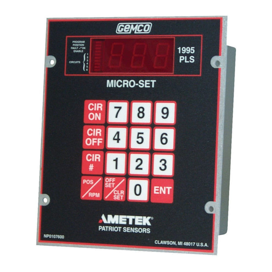
Summary of Contents for Ametek Gemco 1995A Series
- Page 1 Series 1995A Gemco ® Micro-Set Programmable Limit Switch Installation & Programming Manual www.comoso.com...
- Page 2 All Rights Reserved - Made in the U.S.A. Version 0.1 AMETEK has checked the accuracy of this manual at the time it was printed. Any comments you may have for the improvement of this manual are welcomed. AMETEK reserves the right to revise and redistribute the entire contents or selected pages of this manual.
-
Page 3: Table Of Contents
Contents Chapter 1: Introduction/Description Chapter 2: Installation Chapter 3: Programming Chapter 4: Expansion Modules Chapter 5: Fault Check Installation & Maintenance Manual www.comoso.com... - Page 4 Chapter 6: Security Inputs Chapter 7: Remote Circular Display Chapter 8: Troubleshooting Chapter 9: Specifications Chapter 10: Troubleshooting Guide Chapter 11: Wiring Diagrams Installation & Maintenance Manual www.comoso.com...
-
Page 5: Chapter 1: Introduction/Description
Chapter 1: Introduction/Description Chapter 1: Introduction/Description 1995A Micro-Set 1.1: Programmable Features Scale Factor Electronic Offset Reset-to-Preset Motion Detector Expansion Outputs See Section 1.2: General Information - Software Option “P” for more options. 1.2: General Information 1995A Micro-Set 1995A 1995A PLS Installation and Maintenance Manual www.comoso.com... - Page 6 Chapter 1: Introduction/Description SOFTWARE OPTION “P” ENHANCES THE SYSTEM BY OFFERING: Multiple Programs Speed-Induced Offsets Time-Based Outputs 1.3: Controller Features and Functions 1995A Micro-Set Display NOTE: Installation and Maintenance Manual www.comoso.com...
-
Page 7: Chapter 2: Installation
Chapter 2: Installation Chapter 2: Installation 1995A Micro-Set PLS. 1995A Micro-Set 2.1: Mechanical Installation Mounting the 1995 Micro-Set PLS 1995A Micro-Set PLS 1995A 1995A NOTE: 1995A Mounting the Transducer Installation and Maintenance Manual www.comoso.com... - Page 8 Chapter 2: Installation 2.2: Electrical Installation Micro-Set 1995A PLS 2.3: Wiring Instructions 1995A PLS. 1995 Micro-Set only 1995A PLS Installation and Maintenance Manual www.comoso.com...
-
Page 9: Chapter 3: Programming
Chapter 3: Programming Chapter 3: Programming 3.1: Security Input 3.2: Initialization PRIOR 3.3: Scale Factor NOTE: 1995A -or- NOTE: Installation and Maintenance Manual www.comoso.com... - Page 10 Chapter 3: Programming 3.4: Number of Outputs 3.5: Selecting Number of Outputs NOTE: 3.6: Multiprogram (Available Only on “P” Option Units) Installation and Maintenance Manual www.comoso.com...
- Page 11 Chapter 3: Programming 3.7: Setpoint Formula ä ã Programming 1995 PLS for Multiprogram NOTE: Installation and Maintenance Manual www.comoso.com...
- Page 12 Chapter 3: Programming NOTE: 3.8: Setpoints Programming New Setpoints Installation and Maintenance Manual www.comoso.com...
- Page 13 Chapter 3: Programming 180 200 Installation and Maintenance Manual www.comoso.com...
- Page 14 Chapter 3: Programming 3.9: Clear an Existing Setpoint 3.10: Clear All Setpoints -OR- NOTE: 3.11: Setpoint Availability 1995 PLS Installation and Maintenance Manual www.comoso.com...
- Page 15 Chapter 3: Programming 3.12: Electronic Offset Series 1995A PLS Programming the Electronic Offset 3.13: Reset-to-Preset Remote Reset-to-Preset Value 1995A 1995A PLS 1995A PLS Installation and Maintenance Manual www.comoso.com...
- Page 16 Chapter 3: Programming Programming Reset-to-Preset Value NOTE: 3.14: Motion Detector NOTE: Installation and Maintenance Manual www.comoso.com...
- Page 17 Chapter 3: Programming 3.15: Power-Up in a Position or RPM 1995A 3.16: Decimal Point Programming Installation and Maintenance Manual www.comoso.com...
- Page 18 Chapter 3: Programming 3.17: Enable/Disable Outputs NOTE: 3.18: Linear Speed Offset (Available Only on Option “P” Units) Installation and Maintenance Manual www.comoso.com...
- Page 19 Chapter 3: Programming NORMAL PLS DWELL 350 359 1ST COMPENSATION AT 60 RPM 2ND COMPENSATION AT 100 RPM 3RD COMPENSATION AT 140 RPM 4TH COMPENSATION AT 200 RPM Installation and Maintenance Manual www.comoso.com...
- Page 20 Chapter 3: Programming 3.19: Programming 1995 PLS for Linear Speed NOTE: NOTE: NOTE: If “CIR# 501” - “CIR OFF” is set to zero, all linear speeds will be disabled. 3.20: Minimum Speed Disable Installation and Maintenance Manual www.comoso.com...
-
Page 21: Chapter 4: Expansion Modules
Chapter 4: Expansion Modules Chapter 4: Expansion Modules 1995A PLS Remote Circular Displays Remote Circular Display Fig. 4-1 Installation and Maintenance Manual www.comoso.com... - Page 22 Chapter 3: Programming 3.21: Time-Based Outputs (Available Only on Option “P” Units) Linear Speed Offset Time-Based Linear Speed Offset Time-Based NOTE: Time-Based Time-Based Time-Based Time-Based Time-Based NOTE: Time-Based Time-Based Time-Based Linear Speed Offset Time-Based Linear Speed Time-Based Motion Detect Outputs 1 & 2 Linear Speed CIR = 80 - ENT - 2 - ENT Outputs 3 &...
-
Page 23: Chapter 5: Fault Check
Chapter 5: Fault Check Chapter 5: Fault Check NOTE: Installation and Maintenance Manual www.comoso.com... - Page 24 Chapter 5: Fault Check 5.1: PLS Output Status on Fault Conditions Installation and Maintenance Manual www.comoso.com...
-
Page 25: Chapter 6: Security Inputs
Chapter 6: Security Inputs Chapter 6: Security Inputs NOTE: 1995 PLS NOTE: Installation and Maintenance Manual www.comoso.com... -
Page 26: Chapter 7: Remote Circular Display
Chapter 7: Remote Circular Display Chapter 7: Remote Circular Display Remote Circular Display 1995A NOTE: 7.1: POS/RPM On Remote Circular Display Installation and Maintenance Manual www.comoso.com... -
Page 27: Chapter 8: Troubleshooting
Chapter 8: Troubleshooting Chapter 8: Troubleshooting NOTE: 8.1: Preliminary Checks 1995 PLS 8.2: Transducer Excitation Voltages NOTE: Installation and Maintenance Manual www.comoso.com... - Page 28 Chapter 8: Troubleshooting 8.3: Electrical Noise and Power Quality Consideration 1995 PLS 8.4: Grounding 8.5: Incoming Power must not NOTE: must 8.6: Low Level Inputs 1995A PLS 1995 PLS Installation and Maintenance Manual www.comoso.com...
- Page 29 Chapter 8: Troubleshooting 1995 PLS 1995 1995 1995 PLS 1995 PLS Installation and Maintenance Manual www.comoso.com...
-
Page 30: Chapter 9: Specifications
Chapter 9: Specifications Chapter 9: Specifications 9.1: 1995 Micro-Set PLS Programmer INPUTS OUTPUTS 9.2: Mechanical Relay (Single Pole, Double Throw) 9.3: AC Solid-State (Single Pole, Normally Open) Installation and Maintenance Manual www.comoso.com... - Page 31 Chapter 9: Specifications 9.4: DC Solid-State (Single Pole, Normally Open) 9.5: 1995E Output Expansion Module 9.6: 1995-1446 Remote Circular Display Installation and Maintenance Manual www.comoso.com...
-
Page 32: Chapter 10: Troubleshooting Guide
Chapter 10: Troubleshooting Guide Chapter 10: Troubleshooting Guide e r r t i n e i v r e t t i r s t u o i t . t l e i v t l u n i t t i n l a i a z i... - Page 33 Chapter 10: Troubleshooting Guide e t s s e t y l r s t i l l a e t s . s t r o f i t a s i l l l l i e t s i l p e t s a i t i...
- Page 34 Chapter 10: Troubleshooting Guide i s n a l e l l i i f t . e r i s n s e l r o f e r r i t i s . t n r e f r e t i s n .
-
Page 35: Chapter 11: Wiring Diagrams
Chapter 11: Wiring Diagrams Chapter 11: Wiring Diagrams Installation and Maintenance Manual www.comoso.com... - Page 36 Chapter 11: Wiring Diagrams Installation and Maintenance Manual www.comoso.com...
- Page 37 Chapter 11: Wiring Diagrams Installation and Maintenance Manual www.comoso.com...
- Page 38 875A 01/03.Z65 www.comoso.com...
Need help?
Do you have a question about the Gemco 1995A Series and is the answer not in the manual?
Questions and answers