Table of Contents
Advertisement
AMETEK CTS
NetWave
NetWave 3.1, 5, 7, 7.1, 20, 30, 60, 67
NetWave 7.2, 20.1, 30.1, 30.4, 60.1, 67.1
NetWave 7.3, 20.2, 30.2, 60.2, 67.2, 90.2
NetWave 20.3, 30.3, 60.3, 67.3, 90.3, 108.3
NetWave 20.5, 30.5, 67.5, 90.5, 108.5
NetWave 90.3MS
the benchmark for emc
M a n u a l
F o r
O p e r a t i o n
Simulation of the most required power supply
phenomena's
FW Version >7.00.00
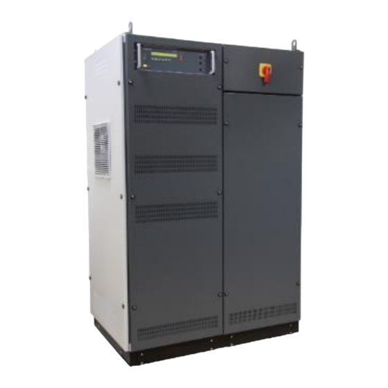
The NetWave is a single and three phase AC power source, specifically
designed to meet the requirements as per IEC/EN 61000-4-8, 13, -14, -17,
-27, -28. It is also serving as a DC power source to cover the requirements
as per IEC/EN 61000-4-29 for voltage dips and interruptions on DC
supplies as well as tests for electrical vehicles.
Its output power with low distortion and high stability, even if supplying
dynamic loads, guarantees full compliant measurements for harmonics
and flicker testing as per IEC/EN 61000-3-2, JIS C 61000-3-2 and IEC/EN
61000-3-3 as well as per IEC/EN 61000-3-11 and IEC/EN 61000-3-12.
Additionally, the NetWave is also well suited for avionics testing as per DO-
160, MIL-STD-704, Airbus ABD0100 and Boeing and testing of electrical
vehicle standards i.e. LV 123 and VW 80300.
Version: 1.60/ 14.12.2020
Replaces: 1.59/ 16.11.2020
Filename: UserManual-Netwave-E-V1.59.docx
Print date: 14.12.20
NetWave
•
IEC 61000-3-2
•
IEC 61000-3-3
•
IEC 61000-3-11
•
IEC 61000-3-12
•
IEC 61000-4-8
•
IEC 61000-4-13
•
IEC 61000-4-14
•
IEC 61000-4-17
•
IEC 61000-4-27
•
IEC 61000-4-28
•
IEC 61000-4-29
•
JIS C 61000-3-2
•
MIL-STD-704
•
RTCA/DO 160
•
Airbus
•
Boeing
•
VW 80300
Advertisement
Table of Contents

Related Manuals for Ametek NetWave 3.1


Summary of Contents for Ametek NetWave 3.1
- Page 1 F o r O p e r a t i o n NetWave NetWave 3.1, 5, 7, 7.1, 20, 30, 60, 67 NetWave 7.2, 20.1, 30.1, 30.4, 60.1, 67.1 NetWave 7.3, 20.2, 30.2, 60.2, 67.2, 90.2 NetWave 20.3, 30.3, 60.3, 67.3, 90.3, 108.3 NetWave 20.5, 30.5, 67.5, 90.5, 108.5...
- Page 2 Switzerland Phone: +41 61 204 41 11 URL: http://www.emtest.com Copyright © 2020 AMETEK CTS GmbH All right reserved. Specifications subject to change Thank you for purchasing the NetWave generator. This user’s manual lists Foreword precautions that must be taken during use and contains useful information about the functions and operating procedure of the device.
-
Page 3: Table Of Contents
AMETEK CTs NetWave Contents Safety..........................5 1.1. Safety Aspects ..........................5 1.2. Safety and warning label on the device .................... 5 1.3. Responsibility of the operator ......................6 1.4. General hazard ..........................6 1.5. Qualification of personnel ......................... 7 Model Overview ......................8 2.1. - Page 4 AMETEK CTs NetWave 10.4. NetWave - Overview Diagram ...................... 130 10.5. NetWave - General Diagram ......................130 11. Declaration of CE-Conformity .................. 131 11.1. CE Conformity NetWave single phase models ................131 11.2. CE Conformity NetWave 20.x ....................... 132 11.3.
-
Page 5: Safety
AMETEK CTs NetWave Safety 1.1. Safety Aspects Observe all precautions to assure your personal safety. The generators comply with Installation Category II (excess voltage section). Pay special attention to safety and operation details! 1.2. Safety and warning label on the device Please take note of the following explanations of the symbols used in order to achieve the optimum benefit from this manual and to ensure safety during operation of the equipment. -
Page 6: Responsibility Of The Operator
Neither AMETEK CTS GmbH, nor any of the subsidiary sales organizations can accept any responsibility for personnel, material or inconsequential injury, loss or damage that results from improper use of the equipment... -
Page 7: Qualification Of Personnel
AMETEK CTs NetWave WARNING Personnel fitted with a heart pacemaker must neither operate the instrument nor approach the test setup while a test is being executed. Only approved accessories, connectors, adapters, etc. are to be used to ensure safe operation. -
Page 8: Model Overview
AMETEK CTs NetWave Model Overview 2.1. NetWave single phase models and extension modules Number of Lines Output Voltage AC (V) (p-n) Output Voltage DC (V) Output Power AC (kVA) Output Power DC (kW) 4.25 Output Current continuous (A) Output Current short term (max. 3s) (A) - Page 9 AMETEK CTs NetWave Models with AC voltage range up to 400 Vac / ±560 Vdc, based on the .3 models and added isolation voltage range of 700Vac / 1000Vdc: - NetWave 20.5 - NetWave 30.5 - NetWave 67.5 - NetWave 90.5 - NetWave 108.5...
- Page 10 AMETEK CTs NetWave 20.2 20.3 30.2 30.3 67.2 67.3 90.2 90.3 108.3 AC Voltage (L-N) AC Voltage (p-p) DC Voltage ✓ ✓ ✓ ✓ ✓ Opt-3 Recovery opt. opt. opt. opt. opt. opt. opt. Opt-3 Parallel opt. opt. opt. opt.
-
Page 11: Delivery Groups And Put In Service
AMETEK CTs NetWave Delivery groups and put in service Identical accessory parts are delivered only once if several devices are ordered. The delivered packing list is in each case valid for the delivery. 3.1. Basic equipment NetWave 3 / 5 / 7 •... -
Page 12: Scope Of Supply Opt-3 Multisource
AMETEK CTs NetWave 3.4. Scope of supply Opt-3 MultiSource • Emergency switch with red button and 3 connectors • 3 Framebus terminators • Control cable Framebus, 4m • Control cable Framebus, 8m • 2 Signal cable BNC, 4m • Calibration certificate •... - Page 13 AMETEK CTs NetWave 3.6.2. Final position Please check the maximum floor loading of the position where the NetWave is places and compare with the weight in kg/m2. NetWave : Weight Area Floor loading device approx. 20.x 740 kg 0.59 m 1260 kg/m 30.x...
- Page 14 The residual current device RCD must be type B if one is installed at the input. Power Nominal Inrush Model Input connector Requirements current curent Netwave 3.1 1 x 230V ±10% Mennekes 817 or 1PH + PE equivalent Netwave 7 3x400V ±10% 18A phase 30 32A phse...
- Page 15 AMETEK CTs NetWave Power Nominal Inrush Model Input connector Requirements current curent Netwave 67.X 400 3x400V ±10% 160A phase 212A phase Phoenix HDFKV 95 3PH+PE Netwave 67.X 480 3x480V ±10% 134A phase 176A phase Phoenix HDFKV 95 3PH+PE Netwave 90.X 400 3x400V ±10%...
- Page 16 AMETEK CTs NetWave Connectors for mains supply NetWave 3 NetWave 7.x Type 223 1-phase CEE Type 32 A Screw terminals NetWave 7.3-208 3- phase NetWave models Screw terminal 50 A Screw terminal Minimum cable cross section (proposed) For exact dimension refer to the cable manufacturer datasheet...
- Page 17 AMETEK CTs NetWave 3.6.9. Control cable wiring 1. Signal control cable Make sure that the bridges for L1, L2, L3 SIGNAL OUT to SOURCE IN are connected. Note 2. Computer – NetWave control cable There are two solutions to connect the computer to the NetWave.
- Page 18 AMETEK CTs NetWave 3.6.10. NetWave 3 and NetWave 5 system cabling Cabling NetWave 3/5. The insulating transformer IT-NetWave is optional for testing Aircraft and Military standards. 3.6.11. NetWave 7 system cabling NetWave 7 with optional insulating transformer for testing Aircraft and Military standards.
- Page 19 AMETEK CTs NetWave 3.6.12. NetWave 7.x system cabling Cabling NetWave 7.x with internal insulating transformer and optional DPA 500N...
- Page 20 AMETEK CTs NetWave 3.6.13. NetWave 7.x with DPA and AT1-NetWaveStep-Up transformer The AT1- NetWave Step-Up transformer will expand the voltage from 300 V to 400. Therefore, it is necessary to enter the transformer ratio 1.333 in the device setup of the NetWave Cabling NetWave 7.x with AT1- NetWave Step-Up transformer and optional DPA 500N...
- Page 21 AMETEK CTs NetWave 3.6.15. Power cable wiring for Harmonic and Flicker Application 1-phase system Example for the cabling with using the DPA 500N Harmonic and Flicker analyzer. 3-phase system Example for the cabling with using DPA 503 Harmonic and Flicker analyzer.
- Page 22 AMETEK CTs NetWave 3.6.16. Power cable wiring for Aircraft and MIL application 1-phase system 3-phase system For DC application the + pole can be connected between one line L1, L2 or L3 and Neutral N...
- Page 23 AMETEK CTs NetWave 3.6.17. Cable wiring NetWave with AMP200N Cabling of NetWave and AMP200Nx...
- Page 24 AMETEK CTs NetWave 3.6.18. Cable wiring NetWave with PFS 503Nxxx.2 Cabling of NetWave and PFS 503Nxxx.2 for testing 3-phase dips and interruptions as per IEC 61000-4-11 and IEC 61000-4-34. Voltage dips and interruptions application with a NetWave operates according the following principle.
- Page 25 AMETEK CTs NetWave 3.6.19. Cable wiring NetWave with Rack incl. integrated AIF 503N16.1, DPA 503N and PFS 503N32.2 Interconnections NetWave Rack Cable Safety Circuit – Emergency Switch Interconnect cable The emergency switches of the NetWave connector SLAVE connector with Hirschmann...
- Page 26 AMETEK CTs NetWave 3.6.20. Limitations when used for Surge testing The following limitations apply when the NetWave is used as AC source during Surge testing according IEC 61000-4-5: Maximum allowed Surge voltage is ± 2 kV Note 3.6.21. Functional test 1.
-
Page 27: Functions
AMETEK CTs NetWave Functions 4.1. Front view controller LED Trigger Stop LED Running Cursor "" "→" LED Power Setup Test ON Button 10 LED output active L1 or Lines L1/L2/L3 Mode 11 Output plugs High / Low / PE ( NetWave 3/7) - Page 28 AMETEK CTs NetWave 4. Test ON Pressing this button will enable the output voltage - TEST ON => LED is on - TEST OFF => LED is off 5. Mode Pressing this button will cyclic rotate the main menus. - Wave Generator...
-
Page 29: 1-Ph Systems
AMETEK CTs NetWave 4.2. 1-ph systems 4.2.1. Rear view NetWave 3 / 3.1 / 5 / 7 / 7.1 / 7.2 The upper part of the NetWave is the control part. The control plugs are at the rear side of the NetWave available. - Page 30 AMETEK CTs NetWave Ventilator controller part Framebus IN / OUT Serial from DPA 500N / 503 Trigger IN1 / IN2 Trigger OUT1 / OUT2 Ethernet port USB port DUT monitor GPIB / IEEE 488 port 10 Heat Sink air output...
- Page 31 AMETEK CTs NetWave Ventilator controller part Framebus IN / OUT Serial from DPA 500N / 503 Trigger IN1 / IN2 Trigger OUT1 / OUT2 Ethernet port USB port DUT monitor GPIB / IEEE 488 port 10 Heat Sink air output...
- Page 32 AMETEK CTs NetWave Ventilator controller part Framebus IN / OUT Serial from DPA 500N / 503 Trigger IN1 / IN2 Trigger OUT1 / OUT2 Ethernet port USB port DUT monitor GPIB / IEEE 488 port 10 Heat Sink air output...
- Page 33 AMETEK CTs NetWave 4.2.2. Rear view NetWave 7.3 The upper part of the NetWave is the control part. The control plugs are at the rear side of the NetWave available. Additionally, to the other models, the NetWave 7.3 has two additional BNC Connectors (17) which allows extended functionality (see annex 9.2).
- Page 34 AMETEK CTs NetWave 4.2.3. Rear view NetWave 7.x System with DPA 500N DPA 500N (optional) Measuring device for Harmonic and Flicker NetWave 7.x EUT power supply cabling for Harmonic and Flicker: Wire from NetWave 7 to DPA 500N Input power source (L-N- PE).
-
Page 35: 3-Ph Systems
AMETEK CTs NetWave 4.3. 3-ph systems 4.3.1. Front view NetWave 20.x / 30.x / 60.x / 67.x Standard NetWave NetWave controller Load hook Main Switch Control relays and fuses Phase generator Input transformer Coasting NetWave with Opt-3 Recovery NetWave controller... - Page 36 AMETEK CTs NetWave Standard NetWave NetWave controller Load hook Main Switch Control relays and fuses Phase generator Input transformer NetWave with Opt-3 Recovery NetWave controller Load hook Main Switch Control relays and fuses Phase generator Input transformer Coasting Recovery module (option)
- Page 37 AMETEK CTs NetWave 4.3.3. Rear view NetWave 20.x / 30.x Mains Supply input 3x400 V Control output panel - Control signals - Trigger input - Trigger output - Interface Output panel for - EUT power - Sense - Interlock - Floating switch Recovery module (option) 4.3.4.
- Page 38 AMETEK CTs NetWave 4.3.5. Rear view NetWave 90.x / 108.x Recovery module (option) Mains Supply input 3x400 V Output panel for - EUT power - Sense - Interlock - Floating switch Control output panel - Control signals - Trigger input...
- Page 39 AMETEK CTs NetWave Signal out (control) Source in (control) Trigger IN1/2 Trigger OUT 1/2 GPIB / IEEE 488 port USB for data storage Ethernet port Serial from DPA 503 Framebus OUT 10 DUT monitor 11 USB 2 option measuring board...
- Page 40 AMETEK CTs NetWave Signal out (control) Source in (control) Trigger IN1/2 Trigger OUT 1/2 GPIB / IEEE 488 port USB for data storage Ethernet port Serial from DPA 503 Framebus OUT 10 DUT monitor 11 USB 2 option measuring board...
- Page 41 AMETEK CTs NetWave Signal out (control) Source in (control) Trigger IN1/2 Trigger OUT 1/2 GPIB / IEEE 488 port USB for data storage Ethernet port Serial from DPA 503 Framebus OUT 10 DUT monitor 11 USB 2 option measuring board 11 USB Interface for Measure &...
- Page 42 AMETEK CTs NetWave 4.3.7. Power panel NetWave 20.x / 30.x (except .5 models) Mains supply input terminal EUT Power output plug Sense input Emergency switch Interlock Switch Floating / Grounded EUT Power output CEE plug NetWave 20.5 / 30.5 Mains supply input terminal...
- Page 43 AMETEK CTs NetWave EUT output terminal NetWave 20.x / 30.x Power output Terminal Plugs for L1, L2, L3, N, PE connection. The size depends on model current. Bracket for cable fixing. NetWave 60.x / 67.x / 90.x / 108.x...
- Page 44 AMETEK CTs NetWave Test supply output Safety labor plugs 6 mm Safety flush-mounting plugs ID/S6AR-N-S Model: with ID/S6AR-N-S snap-in lock and threaded stud are insulated plugs designed for flush mounting in housings and panels. The plugs are designed to mate with sockets KBT6AR-N. The resulting plug connections Correspond socket: are securable by means of snap-in lock.
- Page 45 AMETEK CTs NetWave Interlock Two versions of the Interlock exist, depending on the model. Note for .5 models: the interlock CONTROL must be closed to enable the output. Use either the delivered INTERLOCK Terminator or other external switch. See chapter 10.2 for further explanations.
- Page 46 AMETEK CTs NetWave Using for AC and DC 3 times more current capability for - nominal current - inrush current Imax (3s) - repetitive peak current Mains supply input terminal EUT parallel mode output 1 phase terminal Rated power in parallel mode The technical performance in parallel mode is addition of the 3-phase values for all parameters.
- Page 47 AMETEK CTs NetWave 3 times more current capability for - nominal current - inrush current Imax (3s) - repetitive peak current EUT parallel mode output 1 phase EUT Power output terminal 3 phase for NetWave 60.x/67.x EUT parallel mode output 3 phase for NetWave 90.x/108.x...
-
Page 48: Power Connection And Fuse Location
AMETEK CTs NetWave where the power supply is grounded on different points. This Switch allows the user to disconnect the PE very easy and in shortest time for modify his test setup. Technical data of Floating switch: AC voltage: 360 V (rms) - Page 49 AMETEK CTs NetWave Fuse list Number Current [A] Dimension [mm] Type Description F1 – F3 22x58 General Input Line F4 – F6 10x38 Charge resistor F7 – F8 10x38 Input Auxiliary Transformer F9 - F10 5x20 Output Auxiliary Transformer F11 – F12 3.15...
- Page 50 AMETEK CTs NetWave 4.4.2. NetWave 60.x / 67.x Fuse list Number Current [A] Dimension [mm] Type Description F1 - F3 Blade NH00 General Input Line F4 - F6 14x51 Line Inverter Phase R F7 - F9 14x51 Line Inverter Phase S...
- Page 51 AMETEK CTs NetWave Front side Fuse list Number Current [A] Dimension [mm] Type Description F4 - F6 14x51 Line Inverter Phase R F7 - F9 14x51 Line Inverter Phase S F10 - F12 14x51 Line Inverter Phase T F13 - F15...
- Page 52 AMETEK CTs NetWave Rear side Fuse list Number Current [A] Dimension [mm] Type Description F1 - F3 Blade General input line F22 / F23 10x38 Input Auxiliary Transformer F24 / F25 5x20 Output Auxiliary Transformer F26 / F27 5x20 NetWave Controller...
- Page 53 AMETEK CTs NetWave 4.4.4. NetWave 108.x Front side Fuse list Number Current [A] Dimension [mm] Type Description F4 - F6 14x51 Line Inverter Phase R F7 - F9 14x51 Line Inverter Phase S F10 - F12 14x51 Line Inverter Phase T...
- Page 54 AMETEK CTs NetWave Rear side Fuse list Number Current [A] Dimension [mm] Type Description F1 - F3 Blade General input line F22 / F23 10x38 Input Auxiliary Transformer F24 / F25 5x20 Output Auxiliary Transformer F26 / F27 5x20 NetWave Controller...
-
Page 55: Functions On Netwave 7.3, 20.X, 30.X, 60.X, 67.X, 90.X, 108.X
AMETEK CTs NetWave 4.5. Functions on NetWave 7.3, 20.x, 30.x, 60.x, 67.x, 90.x, 108.x 4.5.1. Setup Menu These NetWave models offer in the setup menu additional functions: Select Operation Mode. Standard: Operating with software Simple AC: Operating with external commands from a XML file... - Page 56 AMETEK CTs NetWave 4.5.3. Source AC Mode In Source AC Mode, the NetWave is used as a simple AC Source, while the output is synchronized to a reference signal on the BNC Trigger IN 2. Reference Signals from 40 Hz to 100 Hz will be synchronized on the output of the NetWave, if the reference signal is within 10% of the nominal frequency set on the NetWave.
-
Page 57: Front Panel Operation
AMETEK CTs NetWave Front Panel Operation 5.1. Power on After switching on, NetWave needs approx. 35s for booting. During this time the display is blank. NetWave is ready when the display shows NetWave and the current version. The NetWave is operated by an easy menu control system. Five function keys are available to select parameters and functions. - Page 58 AMETEK CTs NetWave 5.2.2. Menu WaveGenerator Functions - Selecting files - Play files The output active LED indicates - the active output ( mains active) - the number of phases). Note: Files with 3- phase waves indicate all output channels.
- Page 59 AMETEK CTs NetWave Start, Break and Restart same file Start, Stop and return to WaveGenerator menu 5.2.3. Menu Measurement U / I This function shows the actual voltage and current delivered from the NetWave generator. The measurement is taken from the internal power source measurement module...
- Page 60 AMETEK CTs NetWave Select a file and - Delete - Copy - Load 5.2.5. Setup Menu In the setup menu all settings of the NetWave can be done manually. The following figures show the configuration of the different parameters. How to navigate in the Setup menu Figure 3.2 shows the handling of the Setup menu.
- Page 61 AMETEK CTs NetWave Selected output channel for setting the parameters. Cyclic settings for L1 to L3 if available Mode AC or DC Output Voltage : AC rms / DC Frequency : AC only The 3-phases are not identical (internal and/or external)
- Page 62 AMETEK CTs NetWave Sense function Remark Make sure the sense lines are connected to the correct phase. Otherwise the NetWave will not function properly. Remark Use shielded cables to block external noise from coupling on to the sense lines Remark...
- Page 63 AMETEK CTs NetWave 5.2.7. Source Mode This menu set the source Mode of each line to one of the following mode: - Intern, - Extern (only in DC mode) or - AMP200. Source mode cannot be changed when parallel switching is enabled (parallel switching requires all source as intern defined).
- Page 64 AMETEK CTs NetWave 5.2.9. Number of phases On 3 Phase Systems like NetWave 20.x / 30.x / 60.x/ 90.x you can set the system in Single Phase or Three Phase Mode. * if Parallel Switching option is available and set, then “Three phases” and “Two phases”...
- Page 65 AMETEK CTs NetWave 5.2.11. High Voltage Switching (Opt-3 DC-EVR) With this option it is possible to double the DC voltage range by using two phases simultaneously. The phase 1 is used for +DC and the phase 2 is used for –DC pole. The using of this function is only supported by net.control software.
- Page 66 AMETEK CTs NetWave 5.2.15. DUT Monitor Open collector input for event control during a test or record. The DUT Monitor 1 and DUT Monitor 2 controls the behavior during a test or record. The following settings are offered for the two DUT monitor...
-
Page 67: Warning And Alarm
AMETEK CTs NetWave 5.2.23. Language Selection of the desired language. English : Default setting German : Change to German language 5.3. Warning and Alarm 5.3.1. Warning If the user starts a programmed wave manually at the NetWave where the actual power setup does not fit the programmed wave. - Page 68 AMETEK CTs NetWave Alarm Meaning Error Code binary value Digit: - - - x CVMAX Overvoltage CVMIN Under voltage CTMAX Overtemperature CCRT Inverter Limit Out ( Overcurrent) Digit: - - x - Limit Out ( Overcurrent) Limit Out ( Overcurrent)
-
Page 69: Multi Source Operation
AMETEK CTs NetWave Multi Source Operation 6.1. Opt-3 Multi Source This schema shows the connection of three NetWaves to one NetWave MS. - Page 70 AMETEK CTs NetWave The following steps are required to setup NetWave Multi Source : - The NetWave Master (L1) is setup in the menu “Standalone/Master/Slave” to the mode “Master (L1). The Source is set to function “MultiSource”. The NetWave works as a Master in parallel mode and is phase L1.
- Page 71 AMETEK CTs NetWave The following steps are required to split off from NetWave Multi Source to single NetWaves : The Framebus OUT of the NetWave Master (L1) is not connected. The Framebus OUT of the NetWave Slave (L2) is not connected.
- Page 72 AMETEK CTs NetWave 3 NetWaves in Standalone...
-
Page 73: Opt-3 Cs (Cascade Source)
AMETEK CTs NetWave 6.2. Opt-3 CS (Cascade Source) This schema shows the connection of two NetWaves to one NetWave CS. - Page 74 AMETEK CTs NetWave This schema shows the connection of two NetWaves to NetWave CS with connection box.
- Page 75 AMETEK CTs NetWave The following steps are required to setup NetWave Cascade Source : - The NetWave Master (L,+) is setup in the menu “Standalone/Master/Slave” to the mode “Master (L1, L,+). The Source is set to function “CascadeSource”. The NetWave works as a Master in parallel mode and is phase L or +.
- Page 76 AMETEK CTs NetWave The following steps are required to split off from NetWave Cascade Source to single NetWaves : The Framebus OUT of the NetWave Master (L) is not connected. The Framebus OUT of the NetWave Slave (N) is not connected.
- Page 77 AMETEK CTs NetWave 2 NetWaves in Standalone...
-
Page 78: Changing Operating Mode Master / Slave
AMETEK CTs NetWave 6.3. Changing Operating Mode Master / Slave This feature is available for Firmware V7.03.00 and later only. The NetWave must be in Standalone Mode to be able to change modes. When ordered as Cascade Source or Multi Source system the NetWaves are preset by the factory to Master and Slave operating modes. - Page 79 AMETEK CTs NetWave Continue the instructions in chapter Error! Reference source not found. and Error! Reference source not fo und. to setup the system for MultiSource or CascadeSource configuration.
-
Page 80: Technical Data
AMETEK CTs NetWave Technical data 7.1. 1-phase NetWave 3.x / 5 / 7.x AC / DC Power source NetWave 3 / 3.1 / 5 / 7 / 7.1 NetWave 7.2 / 7.3 0V – 300 V AC (RMS) 0V – 360 V AC (RMS) Output voltage 0V - 425 V DC... - Page 81 AMETEK CTs NetWave Measurements (option) Input channels 2 channels (Opt-1 NWB required) Input voltage ranges 25 V, 50 V, 100 V, 250 V and 500 V; unipolar or bipolar Input current ranges 7 A, 15 A, 30 A, 50 A and 150 A; (set in software)
- Page 82 AMETEK CTs NetWave Safety design per IEC 1010, EN 61010 Power supply 3 x 400 V ± 10% (3P, N, PE) 3 x 208 V ± 10% (3P, N, PE) optional 45 Hz – 65 Hz line frequency Input current max.
-
Page 83: 3-Phase Netwave
AMETEK CTs NetWave 7.2. 3-phase NetWave 7.2.1. 3-phase NetWave 20, NetWave 30, NetWave 60, NetWave 67 AC / DC Power source 0V – 300 V AC (RMS) Output voltage 0V - 425 V DC DC – 5 kHz Output frequency... - Page 84 AMETEK CTs NetWave 7.2.4. 3-phase NetWave 20.3/.5, NetWave 30.3/.5, NetWave 60.3/.5, NetWave 67.3/.5 AC / DC Power source 0V – 400 V AC (RMS) Output voltage 0V - 560 V DC DC – 5 kHz Output frequency Frequency accuracy, 100 ppm...
- Page 85 AMETEK CTs NetWave 7.2.7. General technical data for all 3-phase NetWave Regulation Voltage sense internal or external, 4 wires Uset ≥ 100 V ac or dc: ± 5% of line setting Sense range Distortion (THD) Less than 0.5% (for 50 Hz / 60 Hz) Output voltage Stability Better than 0.1%...
- Page 86 AMETEK CTs NetWave DUT monitoring 2 inputs, configurable Signal output Output Signal of internal arbitrary generator (available only on all 3-phase NetWave models) Source Input Input for external or internal arbitrary signal generator (available only on all 3-phase NetWave models)
- Page 87 AMETEK CTs NetWave Dimension NetWave 20.x / 30.x recovery height (rolls+crane support) 1560 (1784) 1560 (1784) width 1210 deep (over all C+G+M) 630 (755) 630 (755) height with rolls rolls diameter crane support (removable) G Power IN 85 85 H width power IN height power IN K dist.
-
Page 88: Current Limiter Ranges
AMETEK CTs NetWave 7.3. Current Limiter Ranges Minimum (in A) Maximum (in A) Peak Limiter RMS limiter Peak Continous 75Hz<AC Limiter 850Hz<AC DC Model <75Hz <850Hz NW3.1 NW7.1 NW7.2 NW7.3 NW20 NW20.1 NW20.2 NW20.3 NW20.5 NW30 NW30.1 NW30.2 NW30.3 NW30.4 NW30.5... -
Page 89: Graphs
AMETEK CTs NetWave 7.4. Graphs 7.4.1. Graphs NetWave 3.1... - Page 90 AMETEK CTs NetWave 7.4.2. Graphs NetWave 7 / 7.3...
- Page 91 AMETEK CTs NetWave 7.4.3. Graphs NetWave 20 / 20.2 / 20.3 / 20.5...
- Page 92 AMETEK CTs NetWave...
- Page 93 AMETEK CTs NetWave 7.4.4. Graphs NetWave 30 / 30.2 / 30.3 /30.5...
- Page 94 AMETEK CTs NetWave...
- Page 95 AMETEK CTs NetWave 7.4.5. Graphs NetWave 67 / 67.2 / 67.3 / 67.5...
- Page 96 AMETEK CTs NetWave...
- Page 97 AMETEK CTs NetWave 7.4.6. Graphs NetWave 90.2 / 90.3 / 90.5...
- Page 98 AMETEK CTs NetWave...
- Page 99 AMETEK CTs NetWave 7.4.7. Graphs NetWave 108.3 / 108.5...
- Page 100 AMETEK CTs NetWave 7.4.8. Graphs NetWave 90.3MS...
-
Page 101: Power Dissipation
AMETEK CTs NetWave 7.5. Power Dissipation... -
Page 102: Output Impedance For Iec 61000-4-29 Testing
AMETEK CTs NetWave 7.6. Output Impedance for IEC 61000-4-29 testing The standard IEC 61000-4-29 defines the impedance conditions of the dc source during the short interruptions as follow: Generator impedance defined in IEC 61000-4-29 operate in “low impedance” condition, absorbing inrush current from the load (if any), or operate in “high impedance”... -
Page 103: Maintenance
AMETEK CTs NetWave Maintenance 8.1. General The NetWave is maintenance-free. Replacement of storage battery Lithium battery: CR 2032 after approx. 10 years (indicates by memory loss of setting) 8.2. Calibration and Verification 8.2.1. Factory calibration Every EM TEST generator is entirely checked and calibrated as per international standard regulations before delivery. -
Page 104: Fuses
AMETEK CTs NetWave 8.5. Fuses 8.5.1. Fuses NetWave 7 The fuses are located at the right side of the NetWave behind the cover. To replace the user must open the four screws at the right-side cover. Fuses for power unit R, S, T... - Page 105 AMETEK CTs NetWave 8.5.3. Fuses NetWave 30.x The fuses are located at the right side of the NetWave behind the cover. For replace the user must open the four screws at the cover. F1…F3 Fuses for General Input Line R, S, T...
- Page 106 AMETEK CTs NetWave 8.5.4. Fuses NetWave 60.x / 67.x The fuses are located at the rear side of the NetWave behind the cover. For replace the user must open the screws at the cover. F1…F3 Fuses for General Input Line R, S, T...
- Page 107 AMETEK CTs NetWave 8.5.5. Fuses NetWave 90.x The fuses are located at the rear side of the NetWave behind the cover. For replace the user must open the screws at the cover. F1…F3 Fuses for General Input Line R, S, T...
- Page 108 AMETEK CTs NetWave 8.5.6. Fuses NetWave 108.x The fuses are located at the rear side of the NetWave behind the cover. For replace the user must open the screws at the cover. F1…F3 Fuses for General Input Line R, S, T...
-
Page 109: Accessories And Options
AMETEK CTs NetWave Accessories and options 9.1. Opt-1 NWB / Opt-3 NWB (NetWave Measure Board) 1 Phase Systems - Built-in 2 channels measuring board 16 Bit resolution 100 kS/s Input voltage 500 V unipolar or bipolar Input current 150 A unipolar or bipolar... - Page 110 AMETEK CTs NetWave 3 x NetWave 20 -> NetWave 20MS (67.5 kVA, 27 3 x NetWave 20.2 -> NetWave 20.2MS (67.5 kVA, 27 3 x NetWave 20.3 -> NetWave 20.3MS (67.5 kVA, 27 3 x NetWave 30 -> NetWave 30MS (90 kVA, 36 kW) 3 x NetWave 30.2 ->...
-
Page 111: Opt-3 Cascadesource (3 Phase Systems)
AMETEK CTs NetWave Possible device configuration at Opt-3 MS : MS = Multi Source, CS – Cascade Source 20.2 20.3 20.2 20.3 67.2 67.3 90.2 90.3 108.3 AC Voltage (p-n) – MS AC Voltage (p-n) (1 Phase) – CS DC Voltage – MS DC Voltage –... - Page 112 AMETEK CTs NetWave 2 x NetWave 20 -> NetWave 20CS (22.5 kVA, 54 kW) 2 x NetWave 20.2 -> NetWave 20.2CS (22.5 kVA, 54 kW) 2 x NetWave 20.3 -> NetWave 20.3CS (22.5 kVA, 54 kW) 2 x NetWave 30 ->...
-
Page 113: Power Mains Matching Transformer
AMETEK CTs NetWave Possible device configuration at Opt-3 CS : CS = CascadeSource 20.2 20.3 30.2 30.3 67.2 67.3 90.2 90.3 108.3 AC Voltage (L-N) (3 Phase) AC Voltage (L-N) (1 Phase) DC Voltage 1000 1120 1000 1120 1000 1120... -
Page 114: Filter Box F-Box
AMETEK CTs NetWave 9.7. Filter Box F-BOX The filter box is a low pass filter that suppresses high frequency content distortions. It is used in situations where the output noise of the NetWave is too high, i.e. emission measurements. It is mandatory to be used for tests “Voltage Distortion Spectrum” as per MIL-STD-704 LDC/HDC 103 or MIL- STD-461 . - Page 115 AMETEK CTs NetWave Typical filter curve F-Box Application The F-Box is used for testing voltage distortion spectrum under test condition A/B. The figure below illustrates that the F-Box is connected direct at the DC generator output.
-
Page 116: Filter Box L-Box
AMETEK CTs NetWave 9.8. Filter Box L-BOX The Filter box is mandatory to be used for tests “Voltage Distortion Spectrum” as per MIL-STD-704 LDC103 and test condition C and K. L-BOX 1-32 Application: 1-phase NetWave 7 and 3-ph NetWave up to 32... - Page 117 AMETEK CTs NetWave Application The L-Box is used for testing voltage distortion spectrum under test condition C and K. The figure below illustrates that the L-Box is connected direct at the DC generator output.
-
Page 118: C-Box 10/100-1000
AMETEK CTs NetWave 9.9. C-Box 10/100-1000 Application: shunt capacitor for ripple test, i.e. ripple on high voltage DC lines of electrical vehicles Voltage: 700 VAC / 1000 VDC Capacitance: 10 µF and 100 µF, jumper selectable Connector: 6mm lab connectors... -
Page 119: Opt-3 Imd - Insulation Monitoring Device
AMETEK CTs NetWave 9.10. Opt-3 IMD - Insulation Monitoring Device The insulation monitor is an external device connected to the NetWave. It constantly monitors the insulation resistance of the phases (L1, L2, L3) to the protective earth. In case the insulation resistance is below a set limit, the safety circuit is tripped and the output of the NetWave is switched off. - Page 120 AMETEK CTs NetWave Wiring diagram Wiring: Interconnection cable from NetWave to IMD, 5 wires (L1, L2, L3, N, PE) Emergency switch interconnection cable from NetWave to IMD Emergency switch button with cable connected to IMD The IMD is tested and delivered with these standard settings:...
-
Page 121: Annex
AMETEK CTs NetWave 10. Annex 10.1. Manual firmware update A: After the installation or update of the net.control software. A message box may automatically appear if net.control software detects an older firmware on the NetWave. 1a. Press the OK button to enter the Device update window. - Page 122 AMETEK CTs NetWave After “download” the NetWave display shows: NetWave 7 REMOTE NetWave.tgz stored The message “File Stored” confirms the successful download of the new firmware to NetWave. Press the Reboot button for booting the NetWave. During the booting process the NetWave will install the new firmware version.
-
Page 123: Interlock Feature
AMETEK CTs NetWave 10.2. Interlock Feature There are two versions of the interlock available that depend on the model and the serial number: All models except xx.5: interlock that indicates the operating status, no control xx.5 models: enhanced interlock with control and auxiliary contacts... - Page 124 AMETEK CTs NetWave Note: see above for power ratings of relay contacts. 10.2.2. Interlock CONTROL NetWave models with the CONTROL interlock feature offer additional interlock functionalities. It allows to actively control the output switch of the NetWave. It also includes two relay contacts that indicate the status of the switch.
- Page 125 AMETEK CTs NetWave Possible connection diagram for external switch and warning lamp using The external switch closes the 24 VAC control signal to the output breaker. In parallel two auxiliary relays are connected that indicate the status of the output breaker.
-
Page 126: Trigger Out Signals
AMETEK CTs NetWave 10.3. Trigger Out Signals Trigger OUT at Start Trigger OUT at Stop Trigger OUT at Cycle Trigger OUT at Break... - Page 127 AMETEK CTs NetWave Trigger OUT at Start Trigger OUT at Stop Trigger OUT at Cycle Trigger OUT at Start...
- Page 128 AMETEK CTs NetWave Trigger OUT at Stop Trigger OUT at Cycle Trigger OUT at Iteration Trigger OUT at Start...
- Page 129 AMETEK CTs NetWave Trigger OUT at Stop Trigger OUT at Cycle Trigger OUT at Break...
-
Page 130: Netwave - Overview Diagram
AMETEK CTs NetWave 10.4. NetWave - Overview Diagram 10.5. NetWave - General Diagram... -
Page 131: Declaration Of Ce-Conformity
NetWave 11. Declaration of CE-Conformity 11.1. CE Conformity NetWave single phase models Manufacturer: Ametek CTS GmbH Address: Sternenhofstrasse. 15 CH 4153 Reinach Switzerland Declares, that under is sole responsibility, the product’s, listed below, including all their options, are conformity with the applicable CE directives listed below using the relevant section of the following EC standards and other normative documents. -
Page 132: Ce Conformity Netwave 20.X
AMETEK CTs NetWave 11.2. CE Conformity NetWave 20.x Manufacturer: Ametek CTS GmbH Address: Sternenhofstrasse. 15 CH 4153 Reinach Switzerland Declares, that under is sole responsibility, the product’s, listed below, including all their options, are conformity with the applicable CE directives listed below using the relevant section of the following EC standards and other normative documents. -
Page 133: Ce Conformity Netwave 30.X
AMETEK CTs NetWave 11.3. CE Conformity NetWave 30.x Manufacturer: Ametek CTS GmbH Address: Sternenhofstrasse. 15 CH 4153 Reinach Switzerland Declares, that under is sole responsibility, the product’s, listed below, including all their options, are conformity with the applicable CE directives listed below using the relevant section of the following EC standards and other normative documents. -
Page 134: Ce Conformity Netwave 60.X
AMETEK CTs NetWave 11.4. CE Conformity NetWave 60.x Manufacturer: Ametek CTS GmbH Address: Sternenhofstrasse. 15 CH 4153 Reinach Switzerland Declares, that under is sole responsibility, the product’s, listed below, including all their options, are conformity with the applicable CE directives listed below using the relevant section of the following EC standards and other normative documents. -
Page 135: Ce Conformity Netwave 67.X
AMETEK CTs NetWave 11.5. CE Conformity NetWave 67.x Manufacturer: Ametek CTS GmbH Address: Sternenhofstrasse. 15 CH 4153 Reinach Switzerland Declares, that under is sole responsibility, the product’s, listed below, including all their options, are conformity with the applicable CE directives listed below using the relevant section of the following EC standards and other normative documents. -
Page 136: Ce Conformity Netwave 90.X
AMETEK CTs NetWave 11.6. CE Conformity NetWave 90.x Manufacturer: Ametek CTS GmbH Address: Sternenhofstrasse. 15 CH 4153 Reinach Switzerland Declares, that under is sole responsibility, the product’s, listed below, including all their options, are conformity with the applicable CE directives listed below using the relevant section of the following EC standards and other normative documents. -
Page 137: Ce Conformity Netwave 108.X
AMETEK CTs NetWave 11.7. CE Conformity NetWave 108.x Manufacturer: Ametek CTS GmbH Address: Sternenhofstrasse. 15 CH 4153 Reinach Switzerland Declares, that under is sole responsibility, the product’s, listed below, including all their options, are conformity with the applicable CE directives listed below using the relevant section of the following EC standards and other normative documents. -
Page 138: Ce Conformity Filter Box
AMETEK CTs NetWave 11.8. CE Conformity Filter Box Manufacturer: Ametek CTS GmbH Address: Sternenhofstrasse. 15 CH 4153 Reinach Switzerland Declares, that under is sole responsibility, the product’s, listed below, including all their options, are conformity with the applicable CE directives listed below using the relevant section of the following EC standards and other normative documents. -
Page 139: Ce Conformity L-Box
AMETEK CTs NetWave 11.9. CE Conformity L-Box Manufacturer: Ametek CTS GmbH Address: Sternenhofstrasse. 15 CH 4153 Reinach Switzerland Declares, that under is sole responsibility, the product’s, listed below, including all their options, are conformity with the applicable CE directives listed below using the relevant section of the following EC standards and other normative documents. -
Page 140: Ce Conformity C-Box
AMETEK CTs NetWave 11.10. CE Conformity C-Box Manufacturer: Ametek CTS GmbH Address: Sternenhofstrasse. 15 CH 4153 Reinach Switzerland Declares, that under is sole responsibility, the product’s, listed below, including all their options, are conformity with the applicable CE directives listed below using the relevant section of the following EC standards and other normative documents.
Need help?
Do you have a question about the NetWave 3.1 and is the answer not in the manual?
Questions and answers