
Related Manuals for Lennox E210


Summary of Contents for Lennox E210
-
Page 1: Table Of Contents
PAGE • INDEX • GENERAL DESCRIPTION • THE KEYPAD, MODEL E210 • THE KEYPAD, MODEL E420 • THE KEYPAD REMOTE CONTROLLER (OPTION), MODEL E210 • THE KEYPAD REMOTE CONTROLLER (OPTION), MODEL E420 • FUNCTION UNIT COMMISSIONING SELECTING OPERATING MODE SELECTING SET POINT •... -
Page 2: General Description
(see alarm section). - A group of parameters let the control be programmed for each application. The control supplied incorporated on the unit contains the following devices: MODEL E210 MODEL E420 - Keypad - Keypad Located within the unit. -
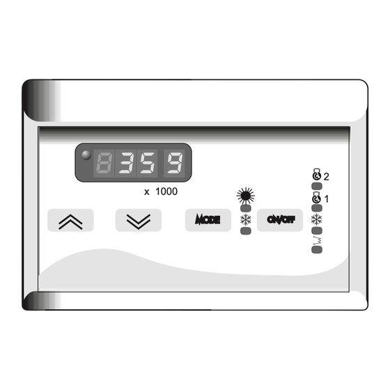
Page 3: The Keypad, Model E210
THE KEYPAD INCORPORATED AT THE UNIT, MODEL E210 READING DISPLAY This is the 3-digit display, The inlet water temperature is shown in degrees (default), ºC (when shows decimal point), o ºF (do not show the decimal point) . The following can also be displayed:... -
Page 4: The Keypad, Model E420
THE KEYPAD INCORPORATED AT THE UNIT, MODEL E420 READING DISPLAY This is the 3-digit display, The inlet water temperature is shown in degrees (default), ºC (when shows decimal point), o ºF (do not show the decimal point) . The following can also be displayed: - Values of all parameters controlled by the equipment: - Cooling set point, cooling differential temperature - Heating set point (heat pump units) and heating differential temperature... -
Page 5: The Keypad Remote Controller (Option), Model E210
THE KEYPAD REMOTE CONTROLLER (OPTION), MODEL E210 READING DISPLAY This is the 3-digit display, The inlet water temperature is shown in degrees (default), ºC (when shows decimal point), o ºF (do not show the decimal point) . The following can also be displayed:... -
Page 6: The Keypad Remote Controller (Option), Model E420
THE KEYPAD REMOTE CONTROLLER (OPTION), MODEL E420 READING DISPLAY This is the 3-digit display, The inlet water temperature is shown in degrees (default), ºC (when shows decimal point), o ºF (do not show the decimal point) . The following can also be displayed: - Values of all parameters controlled by the equipment: - Cooling set point, cooling differential temperature - Heating set point (heat pump units) and heating differential temperature... -
Page 7: Function
FUNCTION UNIT COMMISSIONING When all the instructions in the Operating, Service and Installation Manual have been carried out, the unit can be commissioned as follows: POWER SUPPLY TO THE UNIT - Set the general cut-off switch to ON (if included), when the unit gets under power supply the display will lights up. TURN ON/OFF THE UNIT. -
Page 8: Parameters And Devices
HOW TO GET TO PARAMETERS AND DEVICES A parameter is an internal program reference containing important values which can be set to allow the user or installer to ensure proper operation of the unit. A device is, the status list of the elements that comprises the system Getting to the menu mode enable the user to obtain a status list for the unit's devices, this can be used to read the probe temperatures or the operating hours for example. -
Page 9: Adjusting Water Temperature (Set-Point)
SET POINT THERMOSTAT FUNCTION DESCRIPTION LEVEL 1 LEVEL 2 LEVEL 3 DISPLAY Set point value Cooling set point Visualizes: SET POINT Inlet water temperature Active alarms Set point value Heating set point See page 7, for adjustment of set point of the system The water temperature is thermostatically controlled via a set point and a tolerance range (differential) The operation of these parameters is shown in the following diagram. -
Page 10: Analogue Inputs, Probe Temperatures
Code which appears DESCRIPTION on the display MIN MAX UNIT. VAR. 1 CIRCUIT UNIT MODEL E210 Unit for measure temperature H52=0 the temperature is visualized on ºC H52=1 the temperature is visualized ºF 2 CIRCUITS UNIT MODEL E210 Unit for measure temperature H64=0 the temperature is visualized on ºC... - Page 11 MODIFY PARAMETERS Parameter value DISPLAY Parameter value Visualizes: Inlet water temperature Active alarms Parameter value Press Parameter value Press Parameter value mode Parameter value Press Press on off Parameter value PARAMETER VISUALIZATION PARAMETERS HOW TO GET TO PARAMETERS MENU Press buttons and release within two seconds, the display will show up mode on off...
-
Page 12: Modify Unit Parameters
VAR.: Minimum variation allowed DESCRIPTION MIN MAX UNID. VAR. 1 CIRCUIT UNIT MODEL E210 Alarm switch polarity H45=0 switch opens if out is activated H45=1 switch closed if out is activated Unit for measure temperature H52=0 the temperature is visualized on ºC ºC... -
Page 13: Operating Hours
ON/OFF button and release within two seconds. UNIT CODE PARAMETERS MÁX Operating hours compressor 1 hrs/khrs 9.99 Operating hours compressor 2 (if available) model E210 hrs/khrs 9.99 Operating hours compressor 2 (if available) model E420 hrs/khrs 9.99 No available hrs/khrs 9.99... -
Page 14: Alarm Codes
ALARM CODES MENU STRUCTURE LEVEL 1 DISPLAY MENU Visualizes: SET POINT Inlet water temperature Active alarms Press Probe status mode Press LEVEL 2 Press on off Active alarms Codes ALARMS ----- The unit self-protect through safety devices, when any of these safety devices detect an anomaly, shown in the display in order to advice the installer. - Page 15 ALARM CODES VIS. DESCRIPTION EFFECT ACTION Press the ON/OFF button until the alarm disappeared, if alarm shows up again Unit Anti-freeze alarm •Check the water filter stops Indicates the outlet water temperature is •Check water flow lower than +3ºC. •Check that the water pump is connected to power supply of the unit.
- Page 16 ALARM CODES VIS. DESCRIPTION ACTION EFFECT Press the ON/OFF button until the alarm disappeared, if alarm shows up again check continuity and change the faulty Compressor and fan thermal protection alarm component Compressor circuit 2: •Check refrigerant charge 2 stops - Compressor or fan thermal protection open •Check the refrigerant circuit is not - Faulty power supply...
-
Page 17: Defrost System
DESCRIPTION OF THE DEFROST SYSTEM The defrost process is activated during heating mode in heat pump units, when the outside temperature is low and the outdoor coil could become frozen. To melt the ice the defrost function will switch the unit to cooling operation for a short period. During defrost mode the low pressure is at minimum level, consequently the pressostat is disabled in this mode. -
Page 18: Fan Speed Control
FAN SPEED CONTROL Fan speed control: Management of the fan speed. It is management by a fan speed control plate located at the electrical box of the unit The function of this fan speed control is allowing the unit to operate at very low outside temperatures from -10ºC to 46ºC during cooling mode. - Page 19 INSTALLATION-OPERATION & MAINTENANCE MANUAL x 1000 mode on off CONTROLLER E210 / E420...
- Page 20 : + 31 33 2471 800 fax : + 31 33 2459 220 e-mail : info lennoxbenelux.com POLAND : LENNOX POLSKA SP z o.o. tél. : + 48 22 832 26 61 fax : + 48 22 832 26 62 e-mail : lennoxpolska inetia.pl PORTUGAL : LENNOX CLIMATIZAÇAO LDA.
Need help?
Do you have a question about the E210 and is the answer not in the manual?
Questions and answers