Advertisement
Interface for one DALI bus with up to 64 devices and 32 lighting groups
ZDI-DLI
FEATURES
Possibility of controlling up to 64 DALI ballasts and up to 32 lighting groups.
Scene sending and saving.
Error detection and monitoring.
Burn-in, Stand-by and Auto-off functions.
Manual control through buttons and status indication through display.
1.54" display (128 x 64 pixels) used for setting and notifications.
External power supply of 110/230V 50/60Hz.
Total data saving on KNX bus failure.
Integrated KNX BCU.
Size 67 x 90 x 79mm (4.5 DIN units).
DIN rail assembly (EN 50022), through pressure.
DALI Standard compatible
Conformity with th
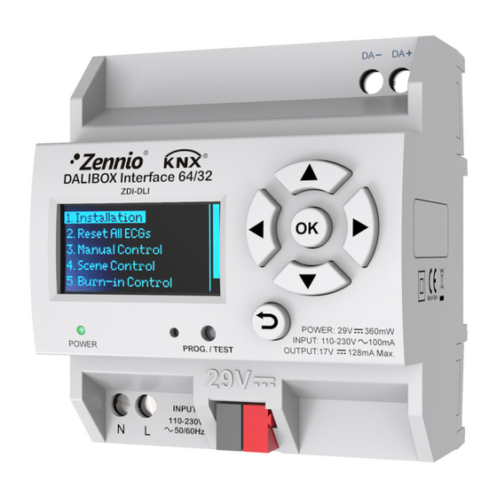
1. DALI bus output
5. External power supply
Programming button: short button press to set programming mode. If this button is held while plugging the device to the KNX bus, it enters into safe
mode.
Programming LED: programming mode indicator (red). When the device enters into safe mode, it blinks (red) every half second. The manual mode is
indicated by the green color. During the start-up (reset or after KNX bus failure) and if the device is not in safe mode, it emits a red flash.
GENERAL SPECIFICATIONS
CONCEPT
Type of device
Voltage (typical)
Voltage range
KNX
Maximum
supply
consumption
Type of connection
Voltage and frequency
Ext. power
supply
Maximum consumption
Operation temperature
Storage temperature
Operation humidity
Storage humidity
Complementary characteristics
Protection class
Operation type
Device action type
Electrical stress period
Degree of protection
Installation
Minimum clearances
Response on KNX bus failure
Response on KNX bus restart
Operation indication
Weight
PCB CTI index
Housing material
(1)
Maximum consumption in the worst case scenario (KNX Fan-In model)
© Zennio Avance y Tecnología S.L.
e
CE directives.
2. Display
6. Programming indicator LED
DESCRIPTION
Electric operation control device
29VDC SELV
21...31VDC
Voltage
29VDC (typical)
(1)
24VDC
Typical bus connector TP1, 0.80mm ø
110/230VAC 50/60Hz
100mA
from 0ºC to +45ºC
from -20ºC to +55ºC
5 to 90% RH (no condensation)
5 to 90% RH (no condensation)
Class B
II
Continuous operation
Type 1
Long
IP20, clean environment
Independent device to be mounted inside electrical panels with DIN rail (EN
50022).
Not required
Data saving according to parameterization
Data recovery according to parameterization
The programming LED indicates programming mode (red). The power supply LED
indicates external power (green). Display allows both configuring the DALI system
and supervising the current status.
180g
175V
PC FR V0 halogen free
Edition 1
DALIBOX Interface 64/32
4
5
Figure 1. DALIBOX Interface 64/32
3. Control buttons
7. Programming button
mA
12.5
15
Technical Documentation
1
7
6
8
4. Power supply indicator LED
8. KNX connector
mW
362.5
360
Page. 1 / 2
2
3
Advertisement
Table of Contents

Related Manuals for Zennio ZDI-DLI


Summary of Contents for Zennio ZDI-DLI
- Page 1 Weight 180g PCB CTI index 175V Housing material PC FR V0 halogen free Maximum consumption in the worst case scenario (KNX Fan-In model) Page. 1 / 2 © Zennio Avance y Tecnología S.L. Edition 1...
- Page 2 • The facility must be equipped with a device that ensures the omnipolar sectioning. Installation of a 10A mini-circuit-breaker is recommended. To prevent accidents, it must remain open in case of manipulation of the device. • The device has a short-circuit protection fuse that, in case of activation, should only be rearmed or replaced by Zennio technical service.
Need help?
Do you have a question about the ZDI-DLI and is the answer not in the manual?
Questions and answers