Sign In
Upload
Manuals
Brands
IAI Manuals
Controller
EC-ST15
IAI EC-ST15 Manuals
Manuals and User Guides for IAI EC-ST15. We have
1
IAI EC-ST15 manual available for free PDF download: Instruction Manual
IAI EC-ST15 Instruction Manual (210 pages)
Brand:
IAI
| Category:
Controller
| Size: 5 MB
Table of Contents
Table of Contents
5
Safety Guide
9
Precautions for Handling
17
International Standard Compliance
19
Precautions for Handling Wireless Operation
20
Precaution for Axis Operation with Wireless Connection
23
Part Names
24
Chapter 1 Specifications
29
Checking the Product
29
Components
29
How to Read the Model Nameplate
30
Checking the Product
30
How to Read the Model Number
31
Mechanical Specifications
32
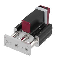
Stopper Cylinder EC-ST15
32
Duty Ratio
38
Options
39
RCON-EC Connection Specification (Model: ACR)
39
With Brake (Model: B)
39
Home Reverse Specification (Model: NM)
39
PNP Specification (Model: PN)
39
Battery-Less Absolute Encoder Specification (Model: WA)
39
Wireless Communication Specification (Model: WL)
39
Wireless Axis Operation Specification (Model: WL2)
40
2-Circuit Power Supply Specification (Model: TMD2)
40
Accessories
41
Power I/O Cable
41
Power I/O Connector
42
Chapter 2 Installation
43
Precautions for Transportation
45
Installation and Storage/Preservation Environment
48
Installation Environment
48
Storage/Preservation Environment
49
Installation of Stopper Cylinder
50
Installation Surface
50
Mounting Orientation Type: EC-ST15L
50
Fixing Bolt
51
Square Nuts
51
Body Mounting
52
Installation to Front Bracket
58
Chapter 3 Wiring
61
System Configuration
63
Electrical Specifications
64
Specifications Table
64
I/O Specifications
65
Brake Release Method (for Specifications with Brakes)
66
Frame Grounding
66
Electrical Specifications
66
Connection Arrangement Diagram
67
Wiring Connections (for Connectors)
69
24VDC Power Supply Wiring
69
PLC Wiring
71
Connector Wiring Method
72
Brake Release Wiring
74
Wiring Connections (for Cables)
74
Power I/O Cable
74
Power I/O Cable Equipped with 4-Way Connector
75
Power I/O Cable Connection
77
24VDC Power Supply Wiring
78
PLC Wiring
80
Brake Release Wiring
81
Chapter 4 Operation
83
Basic Operation
85
Teaching Tool Connections and Testing Operation
86
Teaching Pendant Connection
86
ELECYLINDER Test Operation
87
Stop Position/Operating Conditions (AVD) Setting/Adjustment
88
Stop Position Setting/Adjustment (Forward End/Backward End)
89
Operating Conditions (AVD) Setting/Adjustment
90
Pressing Operation Setting
93
I/O Signals
95
I/O Signal List
95
[ST0] [ST1] Signals: Movement Command Input (Backward/Forward)
96
[RES] Signal: Alarm Clear Input
97
[BKRLS] Input: Brake Release Input
97
[LS0] [LS1] Signals: Position Detection Output (Backward End/Forward End)
98
[PE0] [PE1] Signals: Pressing Complete Output (Backward End/Forward End)
99
[*ALM] Signal: Alarm Output
99
Signal Input Time Constant
99
Operating Method from Master Device
100
Home Return Operation/Positioning Operation: [ST0] [LS0] [ST1] [LS1] Signals
100
Pressing Operation: [ST0] [ST1] [PE0] [PE1] Signals
103
Preventive/Predictive Maintenance
107
Chapter 5 Preventive/Predictive Maintenance
108
Maintenance Information
108
Total Travel Count
108
Total Travel Distance
108
Overload Warning Level
109
Setting Maintenance Information
110
Switching to Maintenance Information Window
110
Basic Operation
111
Chapter 6 Parameters
113
Precautions Regarding Parameters
115
How to Change Parameters
116
Edit Parameters Window
116
Basic Operation
117
Parameter List
119
Parameter Function Descriptions
120
Parameter No.1: Operation Range Adjustment
120
Parameter No.2: Auto Switch "LS" Signal Detection Range Adjustment
121
Parameter No.3: Change Home Return Direction
122
Parameter No.4: Home Position Adjustment
123
Parameter No.5: Smooth Accel/Decel Setting
124
Parameter No.6: Current Control Setting at Stop
125
Parameter No.7: Wireless Function Setting
126
Parameter No.8: Power-Saving Setting
127
Chapter 7 Troubleshooting
131
Troubleshooting Confirmations
131
Troubleshooting Diagnosis
134
Troubleshooting with no Alarm Generated
136
Operation Failure
136
Abnormal or Unstable Operation
138
Troubleshooting by Alarm Groups
140
Alarm Group A: Overload Alarm
141
Alarm Group B: Motor Abnormality Alarm
142
Alarm Group C: Controller Abnormality Alarm
143
Alarm Group D: Controller-Encoder Abnormality Alarm
144
Alarm Group E: Supply Voltage/Power Capacity Abnormality Alarm
145
Maintenance Warning 1: Total Travel Count
146
Maintenance Warning 2: Total Travel Distance
146
Maintenance Warning 3: Overload Warning Level
147
Chapter 8 Maintenance and Inspection
151
Precautions for Maintenance and Inspection Work
151
Inspection Items and Schedule
153
Stopper Cylinder
153
Grease Supply Timing (Guideline)
153
Visual Inspection Items
154
External Visual Inspection
154
Internal Visual Inspection
155
Cleaning
160
External Cleaning
160
Greasing Method
161
Stopper Cylinder
161
How to Replace Components
164
Controller Replacement
164
Wireless Communication Circuit Board Replacement (Controller Cover (End Cover Assembly) Replacement)
167
Reversing Cover, Gasket Replacement
169
Belt Replacement
174
Motor Replacement
182
Chapter 9 External Dimensions
191
Stopper Cylinder External Dimensions
193
Ec-St15L
193
Chapter 10 Life
195
Concept of Life for Stopper Cylinder
197
Concept of Life for Controller
197
Chapter 11 Warranty
201
Warranty Period
201
Scope of the Warranty
201
Honoring the Warranty
201
Limited Liability
202
Conformance with Applicable Standards/Regulations, Etc
202
And Application Conditions
202
Other Items Excluded from Warranty
202
Chapter 12 Appendix
203
Index
205
Revision History
208
Advertisement
Advertisement
Related Products
IAI EC-S6*AH series
IAI EC-S7*H series
IAI EC-S7*AH series
IAI EC-S6
IAI EC-S7
IAI EC-S6*H series
IAI ELECYLINDER EC SL3
IAI EC-RR6*AH series
IAI EC-RR6
IAI EC ELECYLINDER EC-RP4
IAI Categories
Controller
Digital Camera
Gateway
Industrial Equipment
Security Camera
More IAI Manuals
Login
Sign In
OR
Sign in with Facebook
Sign in with Google
Upload manual
Upload from disk
Upload from URL