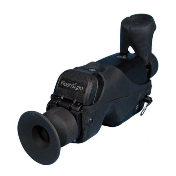
Summary of Contents for FLIR FlashSight
- Page 1 INDIGO OPERATIONS FlashSight™ User’s Guide Copyright © 2006, FLIR Systems, Inc. 431-0002-09-10...
- Page 2 COPYRIGHT Copyright © 2006 by FLIR Systems, Inc. All rights reserved. This publication, or any parts thereof, may not be reproduced in any form without the express written permission of FLIR Systems, Inc.
-
Page 3: Table Of Contents
Table of Contents Introduction.................... 3 Unpacking Your FlashSight..............3 Quick-Start Information ................. 5 FlashSight User Controls ..............7 On/Off Button....................7 Shutter Button....................8 Image Capture Button..................9 Menu Control ....................10 Eyepiece Focus ....................12 Lens Focus ..................... 12 FlashSight Image Download ............... - Page 4 CAUTION It is not possible to charge batteries while they are installed in FlashSight. If using rechargeable batteries, remove them from the battery compartment before charging in the manner specified by the battery manufacturer.
- Page 5 FlashSight™ User’s Guide CAUTION Operating FlashSight outside of its specified operating temperature range or voltage range can cause permanent damage and will void the warranty. CAUTION When not in use, replace the lens cap over the objective lens. When the lens cap is not in place, avoid pointing the sight directly at extremely high-intensity radiation sources, such as the sun, lasers, arc welders, etc.
-
Page 6: Introduction
(13.9° x 9.9°) or 50 mm (8.3° x 6.3°). Unpacking Your FlashSight The items shown in Figure 1 come as part of the deluxe FlashSight kit. The FlashSight camera is also available as a stand alone OEM camera at a reduced cost. - Page 7 FlashSight™ User’s Guide Figure 1: FlashSight Deluxe Kit Copyright © 2006, FLIR Systems, Inc. 431-0002-09-10 Version 100...
-
Page 8: Quick-Start Information
Do not insert batteries directly into the compartment without using the case. 3. Press the on/off button on the left side of the FlashSight assembly as shown in Figure 4. You should hear one or more audible “clicks” from the sight. - Page 9 Figure 3: Installing the battery case into FlashSight Figure 4: Turning on FlashSight Figure 5: Opening the lens cap Figure 6: Adjusting the eyepiece focus Figure 7: Adjusting the infrared lens focus Copyright © 2006, FLIR Systems, Inc. 431-0002-09-10 Version 100...
-
Page 10: Flashsight User Controls
FlashSight™ User’s Guide FlashSight User Controls Figure 8 shows the location of all user controls on the FlashSight. Detailed descriptions for using these controls are described herein. Image Capture (a) Top Lens Cap Menu Control Lens Focus Eyepiece focus Shutter Control... -
Page 11: Shutter Button
In disabled mode, a square marked through with an “x” is shown continuously in the upper left of the image (see part (b) of Figure 9), indicating that FlashSight will not perform automatic shuttering. -
Page 12: Image Capture Button
FlashSight provides internal storage of up to 70 captured images. Image capture is accomplished by pressing then releasing the “Image Capture” button, located on the top of the FlashSight assembly. (Note that the image is captured when you release the button, not when you first press it.) Each time... -
Page 13: Menu Control
4.4 Menu Control FlashSight provides a user control to select and adjust various items using an on-screen menu. This control, which is located on the front of the FlashSight assembly just below the camera lens, is a push-turn device (i.e., it can be rotated like a knob and also pushed like a button). - Page 14 Also, the menu will disappear if the menu control is pressed while the cursor is pointing at the “EXIT” icon. When the menu is off the screen, rotating the menu control will have no effect. Copyright © 2006, FLIR Systems, Inc. 431-0002-09-10 Version 100...
-
Page 15: Eyepiece Focus
5 FlashSight Image Download Figure 13: FlashSight for Image Download To complete the data download, simply plug the USB cable to the FlashSight as shown in Figure 13 and power it on. Windows recognizes the system as a write-protected file-storage device, and images can then be downloaded by copy and paste. -
Page 16: Flashsight Specifications
• Image-storage capacity: <70 frames • Format of stored images: 8-bit uncompressed bit-map (.BMP), approx. 20 kBytes each • Operating Temperature Range: -40°C to +55°C (-40°F to +131°F) • IP rating: 65 Copyright © 2006, FLIR Systems, Inc. 431-0002-09-10 Version 100... -
Page 17: Flashsight Interfaces
• Bench-handling per MIL-STD-810E, Method 516.4, Proc. VI • EMI / EMC: CE Mark certified Note These specifications are subject to change without notice. See the FlashSight Product Specification (ISC doc. 431-0001-01-09) for detailed requirements. FlashSight Interfaces • RS170A (NTSC) compatible-output (75-ohm load impedance) on an SMA connector. -
Page 18: Maintenance
3. Clean rubber eye cup. 4. Reinstall. History of Infrared Less than 200 years ago the existence of the infrared portion of the electromagnetic spectrum wasn't even suspected. The original significance of Copyright © 2006, FLIR Systems, Inc. 431-0002-09-10 Version 100... - Page 19 Figure 16: Marsilio Landriani (1746–1815) Copyright © 2006, FLIR Systems, Inc. 431-0002-09-10 Version 100...
- Page 20 Based upon the differential evaporation of a thin film of oil when exposed to a heat pattern focused upon it, the thermal image could be seen by reflected light where the interference effects of the oil film Copyright © 2006, FLIR Systems, Inc. 431-0002-09-10 Version 100...
- Page 21 Since this involved the risk of giving away the observer’s position to a similarly-equipped enemy observer, it is understandable that military interest in the image converter eventually faded. Copyright © 2006, FLIR Systems, Inc. 431-0002-09-10 Version 100...
- Page 22 This secrecy only began to be lifted in the middle of the 1950’s, and from that time adequate thermal-imaging devices finally began to be available to civilian science and industry. Copyright © 2006, FLIR Systems, Inc. 431-0002-09-10 Version 100...


Need help?
Do you have a question about the FlashSight and is the answer not in the manual?
Questions and answers