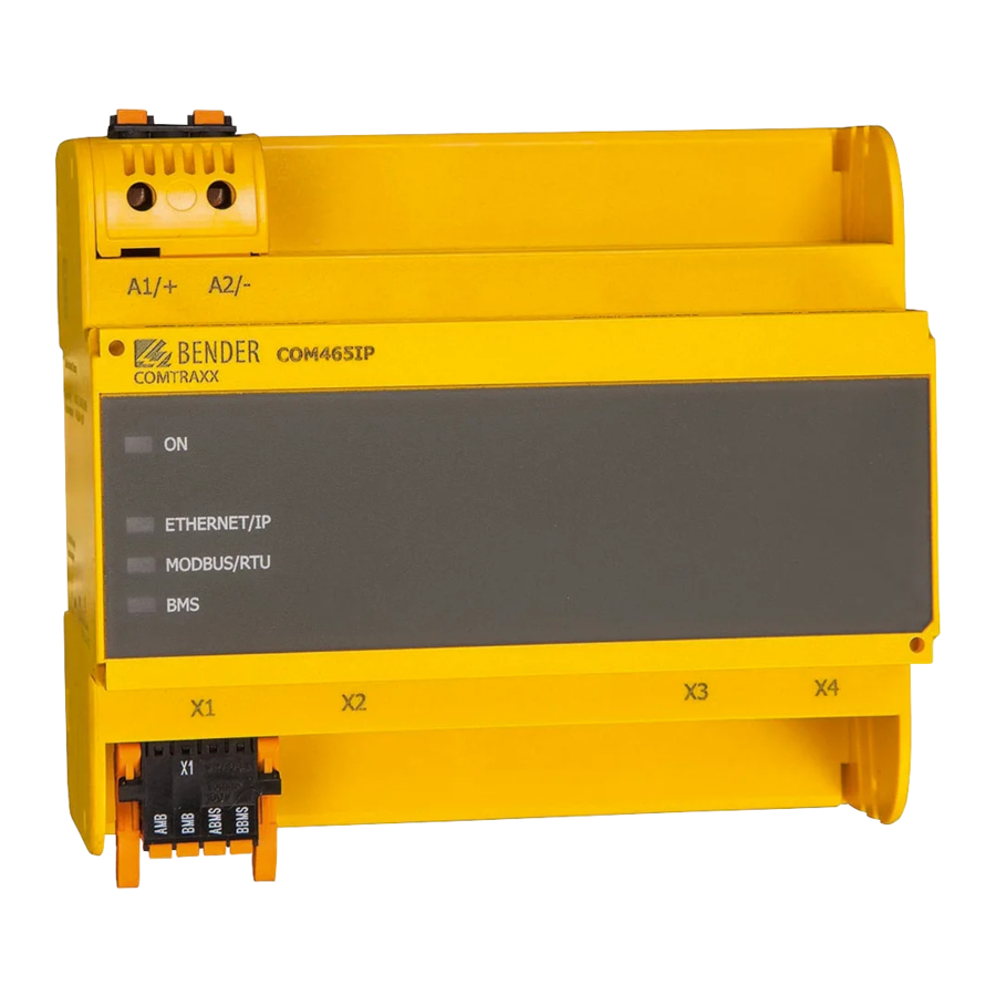
Bender COMTRAXX COM465IP Manual
Condition monitor with integrated gateway
Hide thumbs
Also See for COMTRAXX COM465IP:
- Quick start (4 pages) ,
- Manual (68 pages) ,
- Quick start manual (9 pages)
Table of Contents

Subscribe to Our Youtube Channel
Related Manuals for Bender COMTRAXX COM465IP


Summary of Contents for Bender COMTRAXX COM465IP
- Page 1 Manual COMTRAXX® COM465IP/COM465DP Condition Monitor with integrated Gateway for the connection of Bender devices to PROFIBUS DP and Ethernet-TCP/IP networks Software version: D472 V2.0x COM465IP-COM465DP_D00216_00_M_XXEN/10.2015...
- Page 2 Bender GmbH & Co. KG © Bender GmbH & Co. KG All rights reserved. P.O. Box 1161 • 35301 Gruenberg • Germany Londorfer Straße 65 • 35305 Gruenberg • Germany Reprinting only with permission Tel.: +49 6401 807-0 • Fax: +49 6401 807-259 of the publisher.
-
Page 3: Table Of Contents
Table of Contents 1. Making effective use of this documentation ............. 7 How to use this manual ......................7 Terms used ..........................8 Explanations of symbols and notes ................... 8 2. Safety instructions ....................9 Work on electrical installations ................... 9 Intended use .......................... - Page 4 Table of Contents Connecting the device ......................19 Display and operating elements ..................20 COM465… web user interface ..................20 Commissioning of the device .................... 20 4.7.1 Addresses and their factory settings ................21 4.7.2 Installing GSD file for PROFIBUS DP master (COM465DP only) ......22 5.
- Page 5 Table of Contents 6.2.2 Memory scheme of the process image ................. 40 6.2.2.1 BMS device address assignment on the Modbus ..........40 6.2.2.2 Memory scheme of an individual BMS device ............. 40 6.2.2.3 Device type ........................42 6.2.2.4 Time stamp ........................42 6.2.2.5 C = Common alarm and D = Device lost (device failure) .........
- Page 6 Table of Contents COM465IP-COM465DP_D00216_00_M_XXEN/10.2015...
-
Page 7: Making Effective Use Of This Documentation
Although great care has been taken in drafting this manual, it may nevertheless contain errors and mistakes. The Bender Group cannot accept any liability for injury to persons or damage to property resulting from errors or mistakes in this manual. -
Page 8: Terms Used
Bender measuring device interface (RS-485 interface with BMS protocol) 1.3 Explanations of symbols and notes The following terms and symbols are used to denote hazards and instructions in Bender documen- tation: This signal word indicates that there is a high risk of danger, which will result in death or serious injury if not avoided. -
Page 9: Safety Instructions
The gateway connects the following devices to Ethernet TCP/IP and PROFIBUS DP networks: Bender devices with BMS bus or BCOM interface Bender universal measuring devices PEM… with Modbus RTU or Modbus TCP. The COM465… converts alarms, measured values and statuses from the devices to the Modbus TCP and HTTP protocols. -
Page 10: Delivery Conditions, Guarantee, Warranty And Liability
Safety instructions 2.4 Delivery conditions, guarantee, warranty and liability The delivery and payment conditions set out by Bender apply. The delivery and payment conditions can be obtained from Bender in printed or electronic format. COM465IP-COM465DP_D00216_00_M_XXEN/10.2015... -
Page 11: Product Description
PROFIBUS DP 3.2.1 Function scope of COM465IP and COM465DP Basic device (without function modules) Condition Monitor with a web interface for use with Bender BMS and BCOM devices and universal measuring devices. Supports devices that are connected: ... -
Page 12: Function Module A
Product description Setting internal parameters and the configuration of Bender universal measuring devices and energy meters.** Time synchronisation for all assigned devices History memory (1,000 entries) Data loggers, freely configurable (30 * 10,000 entries) 50 data points from third-party devices (via Modbus RTU or Modbus TCP) can be assigned. -
Page 13: Function Module C
The stored settings can be uploaded into the device again.*** The report function is available for both the gateway and each assigned Bender device. *) The parameterisation of BMS bus devices is only possible if the gateway is connected to the internal BMS bus. -
Page 14: Function
The COM465… are integrated into the existing EDP structure like PCs. After connecting to the net- work and compatible Bender products, all system devices can be accessed from any PC using a standard web browser (e.g. Google Chrome, Mozilla Firefox, Internet Explorer). In this way, all impor- tant system information is directly available. -
Page 15: Description Of Function
BCOM for new and future Bender systems, e.g. ISOMETER® iso685-D. Modbus RTU (RS-485): COM465… on operation as a master for Bender universal measuring devices PEM..3 and also PEM..5 with restricted functionality (full functionality of PEM..5 only via Modbus TCP). -
Page 16: Process Image
Internal and external BMS bus The majority of Bender devices communicate via the internal BMS bus. Individual devices, such as MK800, TM 800 or Bender panels can communicate via both the internal BMS bus (BMS i) and the ex- ternal BMS bus (BMS e). -
Page 17: Installation, Connection And Commissioning
You will find more detailed information on the topic of BMS, in particular about the wiring of bus devices, in the separate document "BMS bus". You can obtain this document at: http:// www.bender.de > Service & support > Download > Operating manuals. 3. Does the computer network comprise a DHCP server? Otherwise, the network data such as the IP address and subnet allocated by the person respon- sible for the electrical installation have to be set manually. -
Page 18: Installation And Connection
Installation, connection and commissioning 4.2 Installation and connection Risk of fatal injury from electric shock! Parts of the system are live. During installation and connection: ► Do not touch parts of the system. ► Disconnect the system from the power supply and protect the system DANGER against accidental switch-on. -
Page 19: Connecting The Device
Power supply: see nameplate and order information PROFIBUS DP connection (COM465DP only) Modbus RTU interface Plug X1 BMS bus (Bender measuring device interface) Ethernet connection (RJ45) for the connection to the PC network as well as to Plug X2 BCOM... -
Page 20: Display And Operating Elements
Installation, connection and commissioning The power supply must be protected using a 6 A fuse. COM465DP-24V, COM465IP-24V Consider connection polarity! COM465DP-230V, COM465IP-230V Connection polarity is arbitrary. 4.5 Display and operating elements Profibus Ethernet/IP ETHERNET/IP Modbus/RTU MODBUS/RTU COM465DP COM465IP Item Function "ON"... -
Page 21: Addresses And Their Factory Settings
Risk of duplicate addresses if BCOM system name is not changed. The factory setting for the system name on all Bender devices is "SYSTEM". If sev- eral systems are established in the same network, there is a risk that addresses will be assigned more than once. -
Page 22: Installing Gsd File For Profibus Dp Master (Com465Dp Only)
It describes the properties of the COM465DP in a standardised format. You can obtain the latest GSD file at: http://www.bender.de > Service & support > Download > Software 1. Select the destination folder to which the GSD file is to be copied. For the exact destination please see the documentation for the program you want to use to program the PROFIBUS mas- ter. -
Page 23: Profibus Dp (Com465Dp Only)
The gateway and its PROFIBUS address are to be made known to the PROFIBUS master. For this pur- pose you will need the file BEND0F27.gsd (see "Scope of delivery" on page 11) A connection from Bender systems with BMS bus and BCOM to PROFIBUS DP using COM465DP can be necessary for various reasons: A PROFIBUS DP device is to react to an event in the BMS world ... -
Page 24: Correct Control Of The Timing On The Com465Dp Using Profibus Commands Is Necessary
PROFIBUS DP (COM465DP only) 5.1.2 Correct control of the timing on the COM465DP using PROFIBUS commands is necessary. Due to the different times the various devices take to respond to the commands, it may occur that responses from previous requests arrive between a request from the PROFIBUS DP master and the related response from the slave, (COM465DP). -
Page 25: Data Access Using Profibus Dp
PROFIBUS DP (COM465DP only) 5.1.5 Data access using PROFIBUS DP PROFIBUS DP offers three methods for reading or writing data: – Type 1: Requesting measured data from devices on the bus – Type 2: Requesting registers in devices on the bus –... -
Page 26: Type 2: Requesting Registers In Devices On The Bus
PROFIBUS DP (COM465DP only) Byte 6: Structure of the byte: Range and unit. For details see "R&U = Range and unit" on page 44. Range validity State Unit Byte 7: Description high: The high byte of the measured value description. For details see "Channel descriptions for the process image"... -
Page 27: Type 3: Writing To Registers In Devices On The Bus
PROFIBUS DP (COM465DP only) Response from the gateway: Byte 0 Byte 1 Byte 2 Byte 3 Byte 4 Byte 5 Byte 6 Byte 7 Byte 8 Byte 9 Numb Reg. 0 Reg. 0 Reg. 1 Reg. 1 Reg. 2 Reg. 2 Reg. - Page 28 PROFIBUS DP (COM465DP only) Response from the gateway: Byte 0 Byte 1 Byte 2 Byte 3 Byte 4 Byte 5 Byte 6 Byte 7 Byte 8 Byte 9 Number 0xFF 0xFF 0xFF 0xFF 0xFF 0xFF 0xFF 0xFF of regis- ters Byte 0: Sequential ID no.
-
Page 29: Programming Examples
BEND0F27.gsd before executing the program. You can download the latest gsd file from the following address on our web site: http://www.bender.de > Service & support > Download > Software 5.2.1 Type 1: Requesting measured data from devices on the bus 5.2.1.1... - Page 30 PROFIBUS DP (COM465DP only) Response from the gateway: Byte 0 Byte 1 Byte 2 Byte 3 Byte 4 Byte 5 Byte 6 Byte 7 Byte 8 Byte 9 Data Data Data Data value value value value Alarm Range Descrip- Descrip- 0xFF high high...
-
Page 31: Example
PROFIBUS DP (COM465DP only) 5.2.1.2 Example 2: Requesting measured value in the event of an IRDH375 alarm The IRDH375 has the BMS address 3, channel 1 is requested. An insulation fault with the measured value 5 kΩ has occurred (alarm). Request to the gateway Byte 0 Byte 1... - Page 32 PROFIBUS DP (COM465DP only) Response from the gateway: Byte 0 Byte 1 Byte 2 Byte 3 Byte 4 Byte 5 Byte 6 Byte 7 Byte 8 Byte 9 Data Data Data Data value value value value Alarm Range Descrip- Descrip- 0xFF high high...
-
Page 33: Example 3: Requesting Irdh375 Device Fault
PROFIBUS DP (COM465DP only) 5.2.1.3 Example 3: Requesting IRDH375 device fault The IRDH375 has the BMS address 3, channel 4 is requested. There is an "earth connection" device fault. Request to the gateway Byte 0 Byte 1 Byte 2 Byte 3 Byte 4 Byte 5 Byte 6... - Page 34 PROFIBUS DP (COM465DP only) Response from the gateway: Byte 0 Byte 1 Byte 2 Byte 3 Byte 4 Byte 5 Byte 6 Byte 7 Byte 8 Byte 9 Data Data Data Data value value value value Alarm Range Descrip- Descrip- 0xFF high high...
-
Page 35: Type 2: Requesting Registers In Devices On The Bus
PROFIBUS DP (COM465DP only) 5.2.2 Type 2: Requesting registers in devices on the bus 5.2.2.1 Example: Requesting a register on the RCMS490-D The RCMS490-D has the BMS address 2. The "Prewarning" menu item is requested. It has the value "50 %". A register has a size of one word. Request to the gateway: Byte 0 Byte 1... -
Page 36: Type 3: Writing To Registers In Devices On The Bus
PROFIBUS DP (COM465DP only) 5.2.3 Type 3: Writing to registers in devices on the bus 5.2.3.1 Example: Writing to a register on the RCMS490-D The RCMS490-D has the BMS address 2. The "Prewarning" menu item is written. It has the value "50 %". -
Page 37: Modbus Tcp Server
6. Modbus TCP server 6.1 Data access using Modbus TCP protocol Requests are sent to the Modbus TCP server in the COM465… using function code FC4 (read input register). The server generates a function-related response and sends it to the Modbus client. 6.1.1 Exception code If a request cannot be answered for whatever reason, the server sends a so-called exception code... -
Page 38: Modbus Responses
Modbus TCP server 6.1.3 Modbus responses The responses consist of 2 bytes per register. The MSB is the first byte. Byte Name Example … … … Byte 7 MODBUS function code 0x04 Byte 8 Byte count 0x04 Byte 9, 10 Value register 0 0x1234 (fictitious value) Byte 11, 12... -
Page 39: Modbus Process Image In The Memory Of The Com465
Modbus TCP server 6.2 Modbus process image in the memory of the COM465… The device holds a process image in memory. This image represents the current statuses and values of up to 150 BMS devices for each monitored internal BMS bus. 6.2.1 Requesting data 6.2.1.1... -
Page 40: Memory Scheme Of The Process Image
Modbus TCP server 6.2.2 Memory scheme of the process image 6.2.2.1 BMS device address assignment on the Modbus As illustrated in the table, the Modbus start address for the respective process image is derived from the BMS device address. 256 (0x100) words or 512 bytes are reserved for each BMS device. They con- tain all the information requested and transmitted from the BMS bus. - Page 41 Modbus TCP server Example: In our example, data are to be requested from channel 2 of the device with BMS address 3. How is the start address determined to send the request for the channel? In our example, the relevant cells in the table are marked in bold.
-
Page 42: Device Type
Modbus TCP server A detailed description of the data formats for the device type, time stamp etc. is given below. 6.2.2.3 Device type Word 0x01 0x02 0x03 0x04 0x05 0x06 0x07 0x08 0x09 0x00 ASCII text, 10 words/20 bytes The device type is set using a BMS bus scan. 6.2.2.4 Time stamp Word 0x0A... -
Page 43: Floating Point Value Of The Bms Channels
Modbus TCP server 6.2.2.7 Floating point value of the BMS channels Word 0x00 0x01 Byte HiByte LoByte HiByte LoByte 31 30 24 23 22 16 15 S E E E E E E E E M M M M M M M M M M M M M M M M M M M M M M M Representation of the bit order for processing analogue measured values according to IEEE 754 S = Sign E = Exponent... -
Page 44: R&U = Range And Unit
Modbus TCP server 6.2.2.9 R&U = Range and unit Meaning Invalid (init) No unit Ω Baud °C °F Second Minute Hour Month X … … … … … Reserved CODE Reserved X … … … … … Reserved Reserved True value True value is smaller True value is larger Invalid value... -
Page 45: Channel Description
Modbus TCP server 6.2.2.10 Channel description Word 0x03 deci- Byte Meaning HiByte LoByte 15 14 13 12 11 10 9 Reserved Insulation fault Overload Overtemperature Failure Line 1 Failure Line 2 Insulation OP light Reserved Distribution board failure Oxygen Vacuum Anaesthetic gas Compressed air 5 bar …... -
Page 46: Channel 33 To 64
Modbus TCP server 6.2.2.11 Channel 33 to 64 Meaning No alarm Prewarning Device error Reserved Alarm (yellow LED), e.g. insulation fault Alarm (red LED) Reserved X … … … Reserved Reserved No test Internal test External test The BMS channels 33 to 64 only provide digital information. The information is coded as an alarm or message type or test type (internal, external). -
Page 47: Reference Data Records Of The Process Image
Modbus TCP server 6.2.3 Reference data records of the process image To make it easier to check the configuration and the Modbus TCP data access to BMS devices, COM465… provides a reference data record at the virtual BMS address 0. A real BMS device cannot have BMS address 0! Address 0 only serves to simulate data access. -
Page 48: Reference Value On Channel 2
Modbus TCP server 6.2.3.3 Reference value on channel 2 The following reference value is stored in this channel: 12.34 A Word 0x14 0x15 0x16 0x17 HiByte LoByte HiByte LoByte HiByte LoByte HiByte LoByte 0x41 0x45 0x70 0xA4 0x00 0x03 0x00 0x4A Floating point value AT&T... -
Page 49: Channel Descriptions For The Process Image
Modbus TCP server 6.2.4 Channel descriptions for the process image Measured value description Value Alarm message Note Operating message 1 (0x01) Insulation fault 2 (0x02) Overload 3 (0x03) Overtemperature 4 (0x04) Failure Line 1 5 (0x05) Failure Line 2 Insulation fault operating theatre 6 (0x06) Insul. - Page 50 Modbus TCP server Measured value description Value Alarm message Note Operating message Battery operation, additional 38 (0x26) Batt.op. UPS safety power supply 39 (0x27) Phase sequ. left Battery-supported safety power 40 (0x28) Failure UPS supply 41 (0x29) 66 (0x42) 67 (0x43) FunctionTest till: Date 68 (0x44)
- Page 51 Modbus TCP server Measured value description Value Alarm message Note Operating message Temperature sensor short-circuit 105 (0x69) Short temp.sensor 106 (0x6A) Temp.sensor open. Connection temperature sensor 107 (0x6B) Fault contactor K1 108 (0x6C) Fault contactor K2 109 (0x6D) 110 (0x6E) 111 (0x6F) No address: Failure BMS device...
- Page 52 Modbus TCP server Measured value description Value Alarm message Note Operating message 201 (0xC9) Line 1 normal op 202 (0xCA) Line 2 normal op 203 (0xCB) Switch. el. 1 on 204 (0xCC) Switch. el. 2 on 205 (0xCD) 206 (0xCE) Auto mode 207 (0xCF) Manual mode...
- Page 53 Modbus TCP server To convert the data of parameters, you will need data type descriptions. Text representation is not necessary in this case. Value Description of parameters: Parameter/measured value invalid. 1023 (0x3FF) The menu item for this parameter is not displayed 1022 (0x3FE) No measured value/no message 1021 (0x3FD)
-
Page 54: Modbus Control Commands
Modbus TCP server 6.2.5 Modbus control commands Commands can be sent to BMS devices by an external application (e.g. visualisation software). Control via Modbus can be enabled or disabled via the menu "Settings" > 3. Modbus > 1. Control". Command structure Write Read Word 0xFC00... - Page 55 Modbus TCP server Control commands for the internal and external BMS bus int/ext Register Register Register Register Function channel command 1-150 Test Isometer 1-99 1-150 Test changeover device PRC 1-99 1-150 Start automatic test changeover 1- >2 End after time T(test) 1-150 Start test generator without changeover...
- Page 56 Modbus TCP server COM465IP-COM465DP_D00216_00_M_XXEN/10.2015...
-
Page 57: Troubleshooting
7.1 Damage in transit If you find transport damage on receipt of the delivery, have this damage confirmed by the delivery agent on handover. In case of doubt, please contact Bender. 7.2 Malfunctions If the COM465… causes malfunctions in the connected networks, please refer to this manual. -
Page 58: Where Do You Get Help
13th August 2005 must be taken back by the manufac- turer and disposed of properly. For more information on the disposal of Bender devices, see our homepage: http://www.bender.de > Service & support > Take-back of old devices... -
Page 59: Technical Data
8. Technical data 8.1 Tabular data ( )* = Factory setting Insulation coordination acc. to IEC 60664-1/IEC 60664-3 (For 230 V variant B95061060) Rated insulation voltage ............................AC 250 V Rated impulse voltage/overvoltage category ......................4 kV/III Pollution degree ................................3 Protective separation (reinforced insulation) between ...............(A1/+, A2/-) - [(AMB, BMB), (ABMS, BBMS), (X2), (X3, X4), (PROFIBUS DP)] Insulation coordination acc. - Page 60 Technical data IP address ..........nnn.nnn.nnn.nnn, can always be reached via: 192.168.0.254, (169.254.0.1)* Netmask......................... nnn.nnn.nnn.nnn (255.255.0.0)* Protocols (depending on function module selected) ....TCP/ IP, Modbus TCP, Modbus RTU, DHCP, SMTP, NTP SNMP Versions ..................................1, 2c, 3 Devices supported............. Requests to all devices (channels) possible (no trap functionality) BMS bus (internal/external) Interface/protocol ..............
- Page 61 Technical data Long-term storage (IEC 60721-3-1) ........................... 1K4 Classification of mechanical conditions acc. to IEC 60721: Stationary use (IEC 60721-3-3) ..........................3M4 Transport (IEC 60721-3-2) ............................2M2 Long-term storage (IEC 60721-3-1) .......................... 1M3 Option "W" data different from the standard version Classification of climatic conditions acc.
-
Page 62: Ordering Information
Function module C B 7506 1013 devices and universal measuring devices Function module D Visualisation of Bender systems, system visualisation B 7506 1014 8.3 Standards, approvals and certificates Certification by the PROFIBUS Nutzerorganisation e.V. (PNO) is available. PROFIBUS conformity: Z02007 UL and GL approval in preparation. -
Page 63: Index
INDEX Measured value descriptions for the proc- ess image, list 49 Address 21 Memory image of a BMS device 41 Memory scheme of the process image 40 Modbus - address structure for BMS devices BMS device address assignment on the Modbus 40 - control commands 54 Byte offset 48... - Page 64 Bender GmbH & Co. KG P.O. Box 1161 • 35301 Gruenberg • Germany Londorfer Straße 65 • 35305 Gruenberg • Germany Tel.: +49 6401 807-0 • Fax: +49 6401 807-259 E-mail: info@bender.de • www.bender.de Fotos: Bender Archiv und bendersystembau Archiv.
Need help?
Do you have a question about the COMTRAXX COM465IP and is the answer not in the manual?
Questions and answers