Advertisement
Quick Links
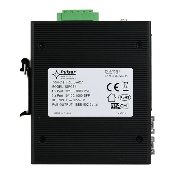
6 ports industrial switch
4 PoE ports 10/100Mb/s, (1÷4 ports) (data and power
supply)
2 ports 10/100/1000Mb/s SFP
30 W for each PoE port, supports devices complaint with
the IEEE802.3af/at (PoE+) standard
Supports auto-learning and auto-aging of MAC addresses
(8K size)
1. Technical description
1.1. General description.
ISFG64 is a 6-ports PoE switch designed to supply IP cameras operating in IEEE 802.3af/at standard.
Automatic detection of any devices powered in the PoE/PoE+ standard is enabled at the 1 – 4 ports of the switch. UP LINK
ports (marked 5 and 6) are used to connect further network devices using fiber optics (using SFP modules - GBIC). On front
panel there is LEDs signaling of the device's status (description in table below). Device has solutions that allow it to be powered
from two sources (emergency power supply, redundant power supply) – in case of a failure of one source, it immediately
switches to backup one.
The PoE technology ensures a network connection and reduces installation costs by eliminating the need to supply a
separate power cable for each device. This method allows supplying other network devices, such as IP phone, wireless access
point or router.
ISFG64
v1.0
Industrial switch ISFG64 (4xPoE, 2xSFP)
Edition: 1 z dnia 16.01.2020
Supercedes the edition: ---------------
Features
:
Possibility of redundant power supply
Mounting on a DIN rail (TH35)
LED indication
warranty – 2 year from the production date
Example of use.
1
PL
EN
Advertisement

Related Manuals for Pulsar ISFG64


Summary of Contents for Pulsar ISFG64
- Page 1 1.1. General description. ISFG64 is a 6-ports PoE switch designed to supply IP cameras operating in IEEE 802.3af/at standard. Automatic detection of any devices powered in the PoE/PoE+ standard is enabled at the 1 – 4 ports of the switch. UP LINK ports (marked 5 and 6) are used to connect further network devices using fiber optics (using SFP modules - GBIC).
- Page 2 1.2 Block diagram. Fig. 1. Block diagram. 1.3 Description of components and connectors. Table 1. (See Fig. 2) Component No. Description (Fig. 2) 4 x PoE ports (1÷4) 2 x UP LINK ports (SFP) Power Socket (V1/V2) Holder for DIN rail The view of the switch .
- Page 3 1.4 Technical parameters Table 2. 6 ports 10/100/1000Mb/s (4 x PoE + 2 x UP LINK) Ports with connection speed auto-negotiation and MDI/MDIX Auto Cross) PoE power supply IEEE 802. 3af/at (1÷4 ports), 52 V DC / 30 W at each port * Protocols, Standards IEEE802.3, 802.3u, 802.3x CSMA/CD, TCP/IP Bandwidth...
- Page 4 Connection schemes...
-
Page 5: Weee Label
Waste electrical and electronic equipment must not be disposed of with normal household waste. According to the European Union WEEE Directive, waste electrical and electronic equipment should be disposed of separately from normal household waste Pulsar sp. j. Siedlec 150, 32-744 Łapczyca, Poland Tel. (+48) 14-610-19-40, Fax. (+48) 14-610-19-50 e-mail: biuro@pulsar.pl,...
Need help?
Do you have a question about the ISFG64 and is the answer not in the manual?
Questions and answers