Table of Contents
Advertisement
Quick Links
Uninterruptible power supply of 4 IP cameras (48VDC)
5 10/100 Mb/s ports
4 PoE ports (data transfer and power supply)
battery charge current
(batteries 1x7Ah / 1x17Ah)
15,4W for each PoE port, supports devices complaint
with the IEEE802.3af standard
Approximate backup time: 4h 59min
CONTENTS
2.1 Requirements
DIN rail mounted switch 5-port DSB54 with buffer power supply
Edition: 4 from 15.11.2017
Supercedes the edition: 3 from 30.03.2017
Features
Example of use .
1
DSB54
v1.0
for 4 IP cameras
:
Metal housing - color black RAL9005 - with
optional possibility of DIN rail mounting (TH35)
Supports auto-learning and auto-aging of MAC
addresses (1K size)
warranty - 2 year from the production date
PL
EN**
Advertisement
Table of Contents

Related Manuals for Pulsar DSB54


Summary of Contents for Pulsar DSB54
-
Page 1: Table Of Contents
DSB54 v1.0 DIN rail mounted switch 5-port DSB54 with buffer power supply for 4 IP cameras Edition: 4 from 15.11.2017 Supercedes the edition: 3 from 30.03.2017 EN** Features Uninterruptible power supply of 4 IP cameras (48VDC) Metal housing - color black RAL9005 - with ... -
Page 2: Technical Description
1. Technical description 1.1. General description. The DSB54 switch is designed for uninterruptible power supply of 4 IP cameras (48VDC voltage) and is housed in with optional possibility of DIN rail mounting (TH35). a metal enclosure The main elements of this system include:... -
Page 3: Description Of Components And Connectors
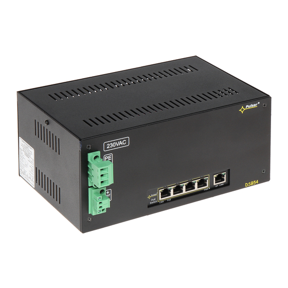
1.3 Description of components and connectors. Fig. 2. The view switch'a - front. Fig. 2b. The view switch'a - rear. Table 1. (See Fig. 2) Component No. Description (Fig. 2) Switch PoE buffer switched mode power supply Power supply connector of the PSU – L, N PE protective connector (electric shock) BAT +, BAT - battery output Holder for DIN rail (80x50) -
Page 4: Technical Parameters
Table 2. (See Fig.3) Component No Description (Fig. 3) 4 x PoE port (1÷4) 1 x UPLINK port 1.4 Technical parameters - parameters of the switch (tab.3) - electrical parameters (tab.4) - mechanical parameters (tab.5) - operation safety (tab.6) - operating parameters (tab.7) Table 3. -
Page 5: Installation
2.2. Installation procedure 1. Before installation, cut off the voltage in the 230V power-supply circuit. 2. Mount the switch DSB54 in a selected location and connect the wires. 3. Connect the power cables (~230Vac) to L-N clips of the PSU. -
Page 6: Indication Of The Device Operation
OFF- no data transmission LAN devices, 10MB/s or ON - the device is connected: 10Mb/s or 100Mb/s Blinking – data transmission 100Mb/s and data transmission The example of mounting the DSB54 switch on a DIN rail (TH35) (DIN rail not included) -
Page 7: Operation And Use
4. Operation and use. 4.1 Overload or short circuit of the PSU output (SCP on). In case of overload, the output voltage is automatically shut off. The restoration of the voltage takes place immediately after the failure (overload) is over. 4.2 Disconnection of discharged battery. - Page 8 The power supply unit is adapted for a sealed lead-acid battery (SLA). After the operation period it must not be disposed of but recycled according to the applicable law. Pulsar Siedlec 150, 32-744 Łapczyca, Poland Tel. (+48) 14-610-19-40, Fax. (+48) 14-610-19-50 e-mail: biuro@pulsar.pl, sales@pulsar.pl http:// www.pulsar.pl, www.zasilacze.pl...
Need help?
Do you have a question about the DSB54 and is the answer not in the manual?
Questions and answers