
Related Manuals for Pulsar INTRE


Summary of Contents for Pulsar INTRE
- Page 1 Interface RS485-ETHERNET v.1.0 INTRE CODE: Edition: 2 from 05.12.2013 Supercedes edition: 1 from 06.01.2013...
-
Page 2: Table Of Contents
INTRE CONTENTS 1. General description..........................3 2. Components arrangement........................3 3. Installation..............................4 3.1 Basic guidelines..................................4 3.2 Connection to the RS485 bus............................... 4 3.3 Connection to the Ethernet network ............................. 4 3.4 Installation of the interface..............................5 4. -
Page 3: General Description
INTRE Features: • operating in the ETHERNET network • compliance with the IEEE 802.3 standard • 10/100BaseT physical layer • transmission speed 10/100Mbps (auto-sensing) • full-duplex or half-duplex operation (auto-sensing) • built-in web server for configuration • data encryption: DES, 3DES, AES •... -
Page 4: Installation
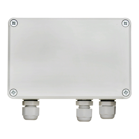
INTRE Table 1. Description of the components. Component No. Description LEDs – optical indication: – supply’s voltage – data transmission – receiving data RST button – reset the interface settings INIT button – initialization of the interface RJ45 Ethernet Interface Socket (see Table 2) -
Page 5: Installation Of The Interface
INTRE 3.4 Installation of the interface. 1. Lead the cable of the RS485 bus through the cable gland and the appropriate hole in the enclosure and then connect to the RS485 connector of the interface. The A+, B- cables should be connected the same way as the rest of devices (A+ to A+, B- to B-) In case of shielded wires, the shield should be connected to the SG signal ground terminals. -
Page 6: Step 1 - Restoring The Factory Settings
INTRE Fig. 3. The wiring diagram between the interface and the PC that enables performing the configuration. The RS485-ETHERNET interface is supplied in basic configuration (factory settings) which is not adapted for correct operation of the system. Since the communication with the interface uses a network cable, there is a need for proper configuration of the router in order to establish a connection with the interface. -
Page 7: Step 2 - The Ip Address Configuration
INTRE 4.4 STEP 2 – The IP address configuration. For proper IP address change, it is recommended to turn off the firewall of the antivirus program for the time of configuration process. Run the ‘Digi Device Discovery’ program with icon. -
Page 8: Step 3 - Configuring The Rs485-Ethernet Interface - Login
INTRE Fig. 6. The window of network settings. In the settings window, select the „Manually configure network settings” option. From now on, the automatically assigned IP address will maintain the same on each connection; it may be left unchanged or changed. -
Page 9: Step 4 - Setting The Communication Mode
INTRE 4.6 STEP 4 – Setting the communication mode. Communication with the RS485-Ethernet interface is possible in various modes. The selection is made by choosing the appropriate profile in the web browser of the interface and configuring the appropriate parameters. - Page 10 INTRE - WAN network communication: Fig.9. The schematic diagram of WAN communication system. The communication between the PC and the final PSU is via the Internet using the public IP address of the router connected to the interface. Data from the router is redirected to the RS485-Ethernet interface, connected to the RS485 bus, and then forwarded to the PSU on the basis of the bus address.
-
Page 11: Tcp Sockets Profile Settings
INTRE TCP Sockets profile settings. After logging in to the interface configuration page, select the “Serial Ports” option from the “Configuration” group and select the „TCP Sockets” profile from the „Select Port Profile” window. Confirm by pressing the „Apply”... -
Page 12: Setting The Serial Port Parameters
INTRE Setting the serial port parameters. Select the „Basic Serial Settings” tab at the bottom of the window and enter the same settings as in the picture below. The power supply units of the EN54 series allow higher transmission speeds - instead of 19.2k 8E1 it can be set to 115.2k 8E1. -
Page 13: Settings In The Powersecurity Program
INTRE Reset the Ethernet interface by pressing the „RST” button on the module or simply disconnect the power supply for a few seconds. After the reset, the connection between the interface and the router should be back after approximately 30 seconds. - Page 14 INTRE After loading the connection configuration, the ”Preview” tab will be displayed. Press the icon in the upper left corner to connect the power supply. Once the connection is established, the current parameters of the power supply, automatically updated according to the refresh cycle set during configuration, will be displayed.
-
Page 15: Communication In The Lan Serial Bridge Mode
INTRE 4.6.2 Communication in the LAN serial bridge mode. The schematic diagram of the communication system in the serial bridge mode is presented in the figure below. Fig.15. The schematic diagram of the communication system in the serial bridge mode. -
Page 16: Setting The Serial Port Parameters
INTRE In the „IP Address” field of the „Client” interface configuration type the real IP address of the „Server” interface. Confirm by pressing the „APPLY” button. If the port 2101 is already in use, choose another one, e.g. 2102. Use the same port number consistently. -
Page 17: Settings In The Powersecurity Program
INTRE Reset the Ethernet interface by pressing the „RST” button on the module or simply disconnect the power supply for a few seconds. After the reset, the connection between the interface and the router should be back after approximately 30 seconds Settings in the PowerSecurity program. - Page 18 INTRE After loading the connection configuration, the ”Preview” tab will be displayed. Press the icon in the upper left corner to connect the power supply. Once the connection is established, the current parameters of the power supply, automatically updated according to the refresh cycle set during configuration, will be displayed.
-
Page 19: Configuration Of Power Supplies
INTRE 5. Configuration of power supplies. Communication in the RS485 bus requires setting appropriate communication parameters in all devices and assigning of unique addresses. The configuration of power supplies of the PSBEN series uses a display located on the front panel of the enclosure. Depending on the display type - LED or LCD - the procedure for changing the settings is different. -
Page 20: Setting The Transmission Parameters
INTRE 5.1.2 Setting the transmission parameters To enter the setup mode, press the „SET” button from the main screen - use the „<” or „>” buttons to display the menu - press the „SET” button - use the „<” or „>” buttons to display the... -
Page 21: Configuration Of Power Supplies Of The Psben Series With Led Display
INTRE 5.2 Configuration of power supplies of the PSBEN series with LED display 5.2.1 Setting the communication address All power supplies are factory-set to address 1. – simultaneously press the „<,>” rightmost and leftmost buttons on the LED panel - press “OK”... -
Page 22: Setting The Transmission Speed And Parity Of The Transmission
INTRE 5.2.2 Setting the transmission speed and parity of the transmission – simultaneously press the „<,>” rightmost and leftmost buttons on the LED panel - The „Adr” parameter will be displayed - press the right arrow „>” - The „trS” parameter will be displayed - press „OK.”... -
Page 23: Configuration Of Power Supplies Of The En54 Series With Lcd Display
INTRE Configuration of power supplies of the EN54 series with LCD display. 5.3.1 Setting the communication address The PSU fitted with LCD display enables setting the communication parameters of the serial port from the LCD panel. To enter the setup mode, press the „SET” button from the main screen use the „<”... -
Page 24: Setting The Transmission Parameters
INTRE 5.3.2 Setting the transmission parameters The power supply units of the EN54 series allow higher transmission speeds - instead of 19.2k 8E1 it can be set to 115.2k 8E1. The changed values apply to all settings. The PSU fitted with LCD display enables setting the communication parameters of the serial port from the LCD panel. -
Page 25: Configuration Of Power Supplies Of The En54 Series With Led Display
INTRE Configuration of power supplies of the EN54 series with LED display 5.4.1 Setting the communication address - simultaneously press the „<,>” rightmost and leftmost buttons - The „tst” parameter will be displayed - use the „<” or „>” buttons to display the „Adr” parameter - press „OK”... -
Page 26: Setting The Transmission Speed
INTRE 5.4.2 Setting the transmission speed The power supply units of the EN54 series allow higher transmission speeds - instead of 19.2k 8E1 it can be set to 115.2k 8E1. The changed values apply to all settings. - simultaneously press the „<,>” rightmost and leftmost buttons - The „tst”... -
Page 27: Setting The Parity Of The Transmission
INTRE 5.4.3 Setting the parity of the transmission - simultaneously press the „<,>” rightmost and leftmost buttons - The „tst” parameter will be displayed - use the „<” or „>” buttons to display the „trP” parameter - press „OK”... -
Page 28: Technical Parameters
Waste electrical and electronic equipment must not be disposed of with normal household waste. According to the European Union WEEE Directive, waste electrical and electronic equipment should be disposed of separately from normal household waste. WARRANTY Pulsar K.Bogusz Sp.j. 5 years from the production date. Siedlec 150, 32-744 Łapczyca, Poland WARRANTY IS VALID only upon presentation of the original Phone (+48) 14-610-19-40, Fax.
Need help?
Do you have a question about the INTRE and is the answer not in the manual?
Questions and answers