Advertisement
Quick Links
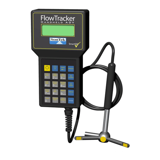
FlowTracker
- Quick Start Guide
®
®
Handheld ADV
for Velocity and Flow Measurements
This sheet is a quick reference to FlowTracker operation.
For more information, refer to the
Technical Manual
detailed
the software CD or via the Start | All Programs | SonTek
Software menu after installation.
What's in the case?
Standard Parts
Part description
FlowTracker
Communications/Power Cable
AA Battery
Toolkit
Quick Start Guide (this guide)
Software Installation CD (includes Manual)
Optional Extras
Part description
Wading Rod
Keypad Mounting Bracket
Probe Mounting Bracket (S or J styles)
Important FlowTracker facts
Handheld Unit
Probe Cable
Probe
Some important tips on the FlowTracker and its use:
No calibration of the unit is required.
The Handheld Unit can withstand temporary
submersion, but should not be used underwater.
There is a built-in temperature sensor in the probe.
Take advantage of the SmartQC™ features;
see manual for details.
What does the FlowTracker do?
The FlowTracker measures velocities with a range as low
User's Manual
or the
, both of which can be found on
LCD Screen
Keypad
Communications/Power
Connector
as 0.001 m/s (0.003 ft/s) and
up to 4.0 m/s (13 ft/s). When
combined with a wading rod,
the FlowTracker can be used
to measure the total discharge
across a river section.
How does it work?
The FlowTracker uses SonTek's exclusive ADV
technology to measure 2-D or 3-D velocities in a small
measurement point located 10 cm from the acoustic
transmitter. This allows
measurement of natural flow
that is free of any disturbance
caused by the instrument.
There are no moving parts on
the FlowTracker.
Where can I use a FlowTracker?
Qty
1
The FlowTracker can be used in:
1
Natural streams
8
Weirs and Flumes
1
Open channels
1
Irrigation
1
Water treatment
Stormwater
Qty
Basic FlowTracker operation
1
1
Install AA batteries in the compart-
1
ment in the back of the unit. To
turn the unit on, hold
second; to turn off, hold
seconds. Always follow the on-
screen instructions and use the
major key functions labeled on the
keypad.
Testing the FlowTracker
Before any extended field trip, you should run a system
diagnostics test using the Beam Check module. This
software should show signal amplitude plots on top of
each other. If not, it is possible the probe may be
damaged. A complete description of Beam Check can be
found in the manual. Use Recorder to download all files
from the recorder and to format it before deployment.
Measuring discharge - Theory
Measuring discharge involves wading across the stream/
river while taking measurements of water depth and
velocity at different locations (based on ISO/USGS
procedures). When combined with depth information, the
total discharge can be computed. This diagram shows the
Mid Section Equation
Section
Japanese Equations
and
Loc
Loc
Loc
0
1
2
W
W
1
2
Dep
Dep
1
2
Area
1
Area
2
Mid Section River Discharge Measurement Equation
Receiver
Measurement
Point (2D or 3D)
English Keypad
Corr.
for one
Factor
1
for four
LEW /
REW
4
Set Ice
Depth
7
PQRS
Abort
0
Five Colors
Black
White
Grey (50%)
Yellow (Pantone Yellow CVC - 100% yellow in CMYK)
Blue (PMS 2935 Coated)
Fonts
Numbers Keys ( 1234567890 . - ): White 20 Point Arial
Alphabet on keys (A-Z): White Arial 8 Point
ENTER: White 9 Point Arial
All yellow text: Yellow 9 Point Arial
used to compute discharge (
are also supported):
Loc
Loc
Loc
Loc
Loc
Loc
Loc
3
4
5
6
7
8
W
W
W
W
W
W
3
4
5
6
7
8
Dep
Dep
Dep
Dep
Dep
Dep
Dep
3
4
5
6
7
8
Area
Area
Area
6
Area
Area
7
Area
Area
3
5
8
4
Station Location = Loc
i
Station Water Depth = Dep
i
Station Width = W = (Loc - Loc )/2 + (Loc - Loc )/2
i
i+1
i
Station Area = Area = W * Dep
i
i
i
Mean Station Velocity = V
i
Station Discharge = Q = Area * V
i
i
i
Total Discharge = Sum( Q )
i
®
Transmitter
Receiver
Delete
Measure
Next
Set
Set
Station
Velocity
Location
2
3
ABC
DEF
Previous
Set Meas
Set
Station
Depth
Depth
5
6
GHI
JKL
MNO
QC
Method
Method
Menu
-
+
8
9
TUV
WXYZ
Calculate
End
Disch.
Section
-
ENTER
.
Mean
Loc
Loc
Loc
9
10
11
12
W
W
W
9
10
11
Dep
Dep
9
10
11
Area
11
Area
10
9
i
i-1
P/N 6054-60211--D
Advertisement

Summary of Contents for YSI SonTek FlowTracker
- Page 1 How does it work? FlowTracker - Quick Start Guide ® ® Handheld ADV for Velocity and Flow Measurements ® The FlowTracker uses SonTek’s exclusive ADV technology to measure 2-D or 3-D velocities in a small This sheet is a quick reference to FlowTracker operation. measurement point located 10 cm from the acoustic For more information, refer to the User’s Manual...
- Page 2 Measuring discharge - Procedure The defaults for these parameters are: Units: English Averaging Time: 40 seconds Select a site with reasonable uniform bottom conditions Mode: Discharge Salinity: 0.0 ppt (freshwater) that may be safely waded (typically no more than 1-m Discharge Equation: Mid Section deep).


Need help?
Do you have a question about the SonTek FlowTracker and is the answer not in the manual?
Questions and answers