Table of Contents
Advertisement
Advertisement
Table of Contents

Related Manuals for YSI YSI 556 MPS


Summary of Contents for YSI YSI 556 MPS
- Page 1 Environmental Distributed by: Air-Met Scientific Pty Ltd Air-Met Sales/Service Air-Met Rental P: 1800 000 744 P: 1300 137 067 F: 1800 000 774 E: hire@airmet.com.au E: sales@airmet.com.au W: www.airmet.com.au Work with Confidence Operations YSI 556 MPS Manual Multi Probe System...
-
Page 3: Table Of Contents
Contents Safety .........................1 General Information...................1 General Information ....................6 Description......................6 Unpacking the Instrument..................7 Features of the YSI 556 Multi-Probe System ............8 Batteries ......................9 Power On ......................14 Setting Display Contrast ..................14 Backlight......................15 General Screen Features ..................15 Keypad Use......................16 2.10 Instrument Reset ....................17 2.11... - Page 4 General Recommendations for Short Term Storage........99 12.2 General Recommendations for Long Term Storage ........99 13. Troubleshooting....................102 14. Appendix A YSI 556 MPS Specifications............105 15. Appendix B Instrument Accessories..............106 16. Appendix C Required Federal Communications Notice ........107 17. Appendix D Health Safety ...................108 18.
- Page 5 20.2 EcoWatch Tutorial..................116 21. Appendix H Calibration Record Information ...........127 21.1 Viewing the Calibration Record (.glp) File ...........127 21.2 Uploading the Calibration Record (.glp) File ..........127 21.3 Understanding the Calibration Record (.glp) File..........127 YSI Incorporated YSI 556 MPS Page iii...
-
Page 7: Safety
IMPORTANT SAFETY INSTRUCTIONS! SAVE THESE INSTRUCTIONS! In essence, the most important safety rule for use of the YSI 556 MPS is to utilize the instrument ONLY for purposes documented in this manual. This is particularly true of the YSI 6117 rechargeable battery pack that contains nickel metal hydride (NiMH) batteries. - Page 8 Instead, contact YSI Customer Service. Refer to Appendix E Customer Service. 8. If the battery pack is removed from the YSI 556 MPS, do not store it in pockets or packaging where metallic objects such as keys can short between the positive and negative terminals.
- Page 9 2. Never allow the positive and negative terminals of the battery pack to become shorted or connected with electrically conductive materials. When the battery pack has been removed from the YSI 556 MPS, store it in a heavy plastic bag to prevent accidental shorting of the terminals.
- Page 10 MPS. 3. Charge the YSI 6117 battery pack with the YSI 616 cigarette lighter charger ONLY when the YSI 6117 is installed in the YSI 556 MPS. 4. Do not expose charger to rain, moisture, or snow. 5. Use of an attachment not recommended or sold by the battery charger manufacturer may result in a risk of fire, electric shock, or injury to persons.
- Page 11 Turning off controls will not reduce this risk. YSI 556 MPS Water Leakage Safety Information The YSI 556 MPS has been tested and shown to comply with IP67 criterion, i.e. submersion in 1 meter of water for 30 minutes with no leakage into either the battery compartment or the main case.
-
Page 12: General Information
YSI 556 MPS is compatible with YSI EcoWatch for Windows software. The YSI 556 MPS assists the user in conforming to Good Laboratory Practice (GLP) standards which help ensure that quality control/quality assurance methods are followed. Battery life is displayed with a fuel gauge, and the user can choose standard alkaline batteries or an optional rechargeable battery pack. -
Page 13: Unpacking The Instrument
2. Use the packing list to ensure all items are present. 3. Visually inspect all components for damage. NOTE: If any parts are missing or damaged, contact your YSI Service Center immediately. Refer to Appendix E Customer Service or www.ysi.com. YSI Incorporated... -
Page 14: Features Of The Ysi 556 Multi-Probe System
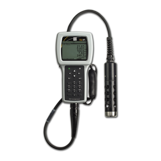
Features of the YSI 556 Multi-Probe System Display Backlight On/Off Key Enter Key Arrow Keys Alpha/Numeric Keys – Used to enter letters and Escape Key numbers Cable Connector Figure 2.1 Front View of YSI 556 MPS Page 8 YSI 556 MPS YSI Incorporated... -
Page 15: Batteries
2.4.1 Battery Life Standard Alkaline Batteries With the standard battery configuration of 4 alkaline C cells, the YSI 556 MPS will operate continuously for approximately 180 hours. Assuming a standard usage pattern when sampling of 3 hours of “on time” in a typical day, the alkaline cells will last approximately 60 days. - Page 16 (+ and -) labels on the bottom of the battery compartment. 4. Check gasket for proper placement on the battery lid. 5. Replace the battery lid and tighten the 4 screws securely and evenly. NOTE: Do not over-tighten the screws. Page 10 YSI 556 MPS YSI Incorporated...
- Page 17 2. Remove the C battery lid and store for future use. Remove C batteries, if installed. 3. Install the rechargeable battery pack and lid and tighten the 4 screws securely and evenly. NOTE: Do not over tighten the screws. YSI Incorporated YSI 556 MPS Page 11...
- Page 18 Section 2.4.3 Inserting Optional Rechargeable Battery Pack. 2. Attach the charger adapter cable (YSI 6119) to the instrument. NOTE: Wall power supplies for use in countries outside the US and Canada can be found in Appendix B Instrument Accessories.
- Page 19 1. Plug the barrel connector of the cigarette lighter charger into the mating end of the YSI 6119 Charger Adapter Cable. 2. Attach the MS-19 end of the YSI 6119 Charger Adapter Cable to the instrument. 3. Make one of the following modifications to the other end of...
-
Page 20: Power On
Troubleshooting. Power On Press and release the on/off button in the upper left corner of the instrument keypad to turn the instrument on or off. See Figure2.1 Front View of YSI 556 MPS. Setting Display Contrast The display contrast automatically compensates for temperature changes. -
Page 21: Backlight
Press and release the backlight key in the upper right corner of the keypad to turn the backlight on or off. See Figure 2.1 Front View of YSI 556 MPS. NOTE: The backlight turns off automatically after two minutes of non-use. -
Page 22: Keypad Use
DEF3def3 GHI4ghi4 JKL5jkl5 MNO6mno6 PQRS7pqrs7 TUV8tuv8 WXYZ9wxyz9 Figure 2.6 Keypad Features 1. See Figure 2.10 Keypad Letters & Numbers and press the appropriate key repeatedly until letter or number desired appears in display. Page 16 YSI 556 MPS YSI Incorporated... -
Page 23: Instrument Reset
2.10 Instrument Reset The YSI 556 MPS is characterized by sophisticated software that should provide trouble-free operation. However, as with all high-capability software packages, it is always possible that the user will encounter circumstances in which the instrument does not respond to keypad entry. -
Page 24: Menu Flowchart
Store Barometer Version Store Site Number Language Edit Site List Data & time Data filter Shut off time System Setup Comma Radix Circuit board SN GLP file name TDS Constant Barometer Units Calibrate barometer Page 18 YSI 556 MPS YSI Incorporated... -
Page 25: Introduction
A 4, 10 or 20 meter cable is directly connected to the probe module body making it waterproof. An MS-19 connector at the end of the cable makes the YSI 5563 fully compatible with the YSI 556 Multi-Probe System. -
Page 26: Features Of The Ysi 5563 Probe Module
If any moisture is present, use compressed air to completely dry the connector. If the connector is corroded, return the probe module to your YSI Distributor or directly to YSI Customer Service. Refer to Appendix E Customer Service. - Page 27 Conductivity/Temperature port port Figure 3.3 Sensor Port Identification 4. Apply a thin coat of o-ring lubricant (supplied in the YSI 5511 maintenance kit) to the o-rings on the connector side of the sensor (see Figure 3.4 O-ring Lubrication). YSI Incorporated...
- Page 28 CAUTION: Do not cross thread the sensor nut. Tighten the nut until it is flush with the face of the probe module bulkhead. Do not over tighten. Bulkhead Seating Figure 3.6 7. Repeat steps 3-6 for any other sensors. Page 22 YSI 556 MPS YSI Incorporated...
- Page 29 Replaceable DO Module Kit. 3.4.2 Membrane Cap Selection The YSI 5563 is shipped with a YSI 5909 kit that contains membrane caps made with 2 mil polyethylene (PE), a material which should be ideal for most field applications of the 556. However, YSI also offers membrane caps made with two other materials (1 mil polyethylene and 1 mil Teflon) which some users may also prefer.
-
Page 30: Transport/Calibration Cup
Section 3 3.4.3 Membrane Cap Installation NOTE: The YSI 5563 DO sensor (already installed in the probe module) was shipped dry. A shipping membrane was installed to protect the electrode. A new membrane cap must be installed before the first use. -
Page 31: Instrument/Cable Connection
1. Line up the pins and guides on the cable with the holes and indentations on the cable connector at the bottom of the YSI 556 instrument. See Figure 2.1 Front View of YSI 556 MPS. 2. Holding the cable firmly against the cable connector, turn the locking mechanism clockwise until it snaps into place. -
Page 32: Sensors
2. Press the Escape key to display the main menu screen. Figure 4.1 Main Menu Screen 3. Use the arrow keys to highlight the Sensor selection. 4. Press the Enter key to display the sensors enabled screen. Enabled sensor Disabled Sensor YSI 556 MPS YSI Incorporated Page 26... - Page 33 Selection for information on the advantages of each type of membrane material. Blue membrane caps using 2 mil polyethylene (PE) were shipped with your YSI 5563 and are likely to be the best choice for most 556 field applications. Figure 4.3 Membrane Selection Screen Highlight the desired membrane choice –...
- Page 34 Enter key to enable or disable it. 6. Repeat step 5 for each sensor you want to change. 7. Press the Escape key to return to the main menu screen. Page 28 YSI 556 MPS YSI Incorporated...
-
Page 35: Report
5. Report The Report Setup screen allows the user to select which sample parameters and units the YSI 556 MPS will display on the screen. It does NOT determine which parameters are logged to memory. Refer to Section 4 Sensors. - Page 36 7. Use the arrow keys to select the units desired, then press the Enter key to return to the report setup screen. 8. Repeat steps 5 and 6 for each parameter you want to change. Page 30 YSI 556 MPS YSI Incorporated...
- Page 37 Run screen with a small ‘c’ after the units of measure. All parameters may be enabled at the same time. Figure 5.4 All Parameters Displayed 9. Press the Escape key to return to the Main menu screen. YSI Incorporated YSI 556 MPS Page 31...
-
Page 38: Calibrate
Ensure that all sensors are immersed in calibration solutions. Many of the calibrations factor in readings from other sensors (e.g., temperature sensor). The top vent hole of the conductivity sensor must also be immersed during some calibrations. Page 32 YSI 556 MPS YSI Incorporated... -
Page 39: Calibration Tips
8. If you are using laboratory glassware, remove the stainless steel weight from the bottom of the probe sensor guard by turning the weight counterclockwise. When the weight is removed, the calibration solutions have access to the sensors YSI Incorporated YSI 556 MPS Page 33... - Page 40 % saturation calibration, make certain that the vessel is vented to the atmosphere by loosening the bottom cap or cup assembly and that approximately 1/8 inch (3 cm) of water is present in the cup. Page 34 YSI 556 MPS YSI Incorporated...
-
Page 41: Calibration Procedures
2. Press the Escape key to display the main menu screen. 3. Use the arrow keys to highlight the Calibrate selection. Figure 6.1 Main Menu 4. Press the Enter key. The Calibrate screen will be displayed. YSI Incorporated YSI 556 MPS Page 35... -
Page 42: Conductivity Calibration
1. Go to the calibrate screen as described in Section 6.2.1Accessing the Calibrate Screen.. 2. Use the arrow keys to highlight the Conductivity selection. See Figure 6.2 Calibrate Screen. 3. Press Enter. The Conductivity Calibration Screen is displayed. Page 36 YSI 556 MPS YSI Incorporated... - Page 43 5. Press Enter. The Conductivity Calibration Entry Screen is displayed. Figure 6.4 Conductivity Calibration Selection Screen 6. Place the correct amount of conductivity standard (see Table 6.1 Calibration Volumes) into a clean, dry or pre-rinsed transport/calibration cup. YSI Incorporated YSI 556 MPS Page 37...
- Page 44 Calibration Volumes, should ensure that the vent hole is covered. 9. Screw the transport/calibration cup on the threaded end of the probe module and securely tighten. NOTE: Do not over tighten as this could cause damage to the threaded portions. Page 38 YSI 556 MPS YSI Incorporated...
- Page 45 13. Observe the reading under Specific Conductance. When the reading shows no significant change for approximately 30 seconds, press Enter. The screen will indicate that the calibration has been accepted and prompt you to press Enter again to Continue. YSI Incorporated YSI 556 MPS Page 39...
-
Page 46: Dissolved Oxygen Calibration
DO sensor before calibrating. 2. Use the arrow keys to highlight the Dissolved Oxygen selection. See Figure 6.2 Calibrate Screen. 3. Press Enter. The dissolved oxygen calibration screen is displayed. Page 40 YSI 556 MPS YSI Incorporated... - Page 47 Figure 6.8 DO Barometric Pressure Entry Screen 3. Place approximately 3 mm (1/8 inch) of water in the bottom of the transport/calibration cup. 4. Place the probe module into the transport/calibration cup. YSI Incorporated YSI 556 MPS Page 41...
- Page 48 7. Press Enter. The DO% saturation calibration screen is displayed. Figure 6.9 DO Sat Calibration Screen 8. Allow approximately ten minutes for the air in the transport/calibration cup to become water saturated and for the temperature to equilibrate before proceeding. Page 42 YSI 556 MPS YSI Incorporated...
- Page 49 1. Go to the DO calibrate screen as described in Section 6.2.3 Dissolved Oxygen Calibration, steps 1 through 3. 2. Use the arrow keys to highlight the DO mg/L selection. 3. Press Enter. The DO mg/L Entry Screen is displayed. YSI Incorporated YSI 556 MPS Page 43...
- Page 50 NOTE: Be sure to completely immerse all the sensors. 5. Use the keypad to enter the known DO concentration of the water. 6. Press Enter. The Dissolved Oxygen mg/L Calibration Screen is displayed. Figure 6.11 DO mg/L Calibration Screen Page 44 YSI 556 MPS YSI Incorporated...
- Page 51 1. Go to the calibrate screen as described in Section 6.2.1 Accessing the Calibrate Screen. 2. Use the arrow keys to highlight the pH selection. See Figure 6.2 Calibrate Screen. 3. Press Enter. The pH calibration screen is displayed. YSI Incorporated YSI 556 MPS Page 45...
- Page 52 2-point calibration, but the software will prompt you to select a third pH buffer. 4. Use the arrow keys to highlight the 2-point selection. Page 46 YSI 556 MPS YSI Incorporated...
- Page 53 7. Carefully immerse the sensor end of the probe module into the solution. 8. Gently rotate and/or move the probe module up and down to remove any bubbles from the pH sensor. YSI Incorporated YSI 556 MPS Page 47...
- Page 54 10. Use the keypad to enter the calibration value of the buffer you are using at the current temperature. NOTE: pH vs. temperature values are printed on the labels of all YSI pH buffers. 11. Press Enter. The pH calibration screen is displayed. Figure 6.14 pH Calibration Screen 12.
-
Page 55: Orp Calibration
1. Go to the calibrate screen as described in Section 6.2.1 Accessing the Calibrate Screen. 2. Use the arrow keys to highlight the ORP selection. See Figure 6.2 Calibrate Screen.. 3. Press Enter. The ORP calibration screen is displayed. YSI Incorporated YSI 556 MPS Page 49... - Page 56 7. Screw the transport/calibration cup on the threaded end of the probe module and securely tighten. NOTE: Do not over tighten as this could cause damage to the threaded portions. Page 50 YSI 556 MPS YSI Incorporated...
- Page 57 The current values of all enabled sensors will appear on the screen and will change with time as they stabilize. NOTE: Verify that the temperature reading matches the value you used in Table 6.2 Zobell Solution Values. YSI Incorporated YSI 556 MPS Page 51...
-
Page 58: Return To Factory Settings
4. Use the arrow keys to highlight the Specific Conductance selection. 5. Press Enter. The Conductivity Calibration Entry Screen is displayed. See Figure 6.4 Conductivity Calibration Entry Screen. 6. Press and hold the Enter key down and press the Escape key. Page 52 YSI 556 MPS YSI Incorporated... - Page 59 8. Press Enter. This returns you to the Conductivity Calibrate Selection Screen, See Figure 6.3 Conductivity Calibration Selection Screen. . 9. Press Escape to return to the calibrate menu. See Figure 6.2 Calibrate Screen. YSI Incorporated YSI 556 MPS Page 53...
-
Page 60: Run
4. Rapidly move the probe module through the sample to provide fresh sample to the DO sensor. 5. Watch the readings on the display until they are stable. 6. Refer to Section 9 Logging for instructions on logging sample data. Page 54 YSI 556 MPS YSI Incorporated... -
Page 61: File
8. File The File menu allows the user to view, upload or delete sample data and calibration record files stored in the YSI 556 MPS. Accessing the File Screen 1. Press the On/off key to display the run screen. 2. Press the Escape key to display the main menu screen. -
Page 62: Directory
3. Press the Enter key. The file list screen is displayed. NOTE: Files are listed in the order in which they are logged to memory. Sample Data files have the file extension .dat, while Calibration Record files have the file extension .glp. Page 56 YSI 556 MPS YSI Incorporated... - Page 63 Figure 8.4 File Details Screen 6. Press the Enter key to view the file data. Refer to Section 8.3 View File for details. 7. Press the Escape key repeatedly to return to the main menu screen. YSI Incorporated YSI 556 MPS Page 57...
-
Page 64: View File
Figure 8.5 File Data Screen 6. Use the arrow keys to scroll horizontally and/or vertically to view all the data. 7. Press the Escape key repeatedly to return to the main menu screen. Page 58 YSI 556 MPS YSI Incorporated... -
Page 65: Upload To Pc
8.4.1 Upload Setup 1. Disconnect the YSI 5563 Probe Module from the YSI 556 MPS instrument. 2. Connect the YSI 556 MPS to a serial (Comm) port of your computer via the 655173 PC Interface cable as shown in the following diagram:... - Page 66 1. Setup the instrument as described in Section 8.4.1 Upload Setup. 2. Go to the YSI 556 MPS file screen as described in Section 8.1 Accessing the File Screen. 3. Use the arrow keys to highlight the Upload to PC selection.
- Page 67 6. After the file transfer is complete, close the terminal window (small window on the PC) by clicking on the “X” at its upper right corner. 7. Press the Escape key on the YSI 556 MPS repeatedly to return YSI Incorporated YSI 556 MPS...
- Page 68 1. Setup up the instrument as described in Section 8.4.1 Upload Setup. 2. Go to the YSI 556 MPS file screen as described in Section 3. Use the arrow keys to highlight the Upload to PC selection. See Figure 8.2 File Screen.
-
Page 69: File Memory
NOTE: If the amount of free memory is low, it may be time to delete all files (after first uploading all data to a PC). Refer to Section 8.6 Delete All Files. 5. Press the Escape key repeatedly to return to the main menu screen. YSI Incorporated YSI 556 MPS Page 63... -
Page 70: Delete All Files
3. Press the Enter key. The Delete all Files screen is displayed. Figure 8.5 Delete All Files Screen 4. Use the arrow keys to highlight the Delete selection. 5. Press the Enter key. Page 64 YSI 556 MPS YSI Incorporated... - Page 71 The progress of file deletion is displayed in bar graph format. NOTE: Deleting all files in the directory will not change any information in the site list. 6. Press the Escape key repeatedly to return to the main menu screen. YSI Incorporated YSI 556 MPS Page 65...
-
Page 72: Logging
2. Press the Escape key to display the main menu screen. Figure 9.1 Main Menu 3. Use the arrow keys to highlight the Logging setup selection. 4. Press the Enter key. The logging setup screen is displayed. Figure 9.2 Setup Screen Page 66 YSI 556 MPS YSI Incorporated... -
Page 73: Setting Logging Interval
See Figure 9.2 Logging Setup Screen. 3. Press the Enter key until a check mark is entered in the box next to the store barometer selection if you want to log barometric readings. YSI Incorporated YSI 556 MPS Page 67... -
Page 74: Creating A Site List
Description will be characterized primarily by the file name, but will also have the Site name attached, so that it is viewable in either the YSI 556 MPS File directory or in EcoWatch for Windows after upload to a PC •... - Page 75 However, each data point has a Site Number attached to it so that the user can easily determine the sampling site when viewing the data from the YSI 556 MPS File menu or processing the data in EcoWatch for Windows after upload to a PC.
- Page 76 6. Use the arrow keys to highlight the Edit site list selection. 7. Press the Enter key. The edit site list screen is displayed. See Figure 9.7 Edit Site List Screen. The Filename field is ready for input. Page 70 YSI 556 MPS YSI Incorporated...
- Page 77 13. Press Enter. The cursor moves to the next filename entry position. 14. Repeat Steps 8 to 13 until all filenames and sites have been entered. 15. Press Escape repeatedly to return to the main menu screen. YSI Incorporated YSI 556 MPS Page 71...
-
Page 78: Editing A Site List
1. Follow Steps 1 through 5 in Section 7.1 Real-Time Data. 2. Use the arrow keys to highlight the Log one sample selection on the run screen if only a single sample is being logged. Page 72 YSI 556 MPS YSI Incorporated... - Page 79 4. Use the keypad to enter a file name. Refer to Section 2.9 Keypad Use. NOTE: The instrument will assign a default file name of NONAME if no file name is specified. 5. Press the Enter key to input the file name. YSI Incorporated YSI 556 MPS Page 73...
- Page 80 11. If a single point is being logged, the header on the run screen changes momentarily from Menu to Sample logged to confirm that the point was successfully logged. Skip to Step Figure 9.11 Sample Logged Screen Page 74 YSI 556 MPS YSI Incorporated...
-
Page 81: Logging Data With A Site List
OR Use the arrow keys to highlight the Start logging selection on the run screen if a data stream is being logged. See Figure 9.9 Run Screen. 4. Press the Enter key. The Pick a site screen is displayed. YSI Incorporated YSI 556 MPS Page 75... - Page 82 If a continuous stream of points is being logged, the start logging entry in the run screen changes from Start logging to Stop logging. See Figure 9.12 Logging Screen. 8. At the end of the logging interval, press Enter to stop logging. Page 76 YSI 556 MPS YSI Incorporated...
-
Page 83: Adding Data To Existing Files
NOTE: The right column shows parameters used when the file was created. The left column shows current parameters. 1. Press the Down Arrow key to scroll down and find the mismatch(es). 2. Use the following chart to resolve the mismatch(es). YSI Incorporated YSI 556 MPS Page 77... - Page 84 Site present in left Number setting Site List column, but missing from right column 3. Return to Section 9.6 Logging Data without a Site List or 9.7 Logging Data with a Site List. Page 78 YSI 556 MPS YSI Incorporated...
-
Page 85: System Setup
10. System Setup The YSI 556 MPS has a number of features that are user-selectable or can be configured to meet the user’s preferences. Most of these choices are found in the System setup menu. 10.1 Accessing the System Setup Screen 1. -
Page 86: Language Setting
YSI 556 MPS. As software enhancements are introduced, you will be able to upgrade your YSI 556 MPS from the YSI Web site. Refer to Section 11.2 Upgrading YSI 556 MPS Software for details. 10.2 Language Setting 1. - Page 87 4-digit year selection. NOTE: If unchecked, a 2-digit year is used. 8. Use the arrow keys to highlight the Date selection. 9. Press Enter. A cursor appears over the first number in the date. YSI Incorporated YSI 556 MPS Page 81...
-
Page 88: Data Filter
The Data Filter is a software filter that eliminates sensor noise and provides more stable readings. NOTE: YSI recommends using the default values for the data filter for most field applications. However, users who are primarily interested in a fast response from their dissolved oxygen sensor should consider a change of the default time constant setting of 8 seconds to one of 2 seconds. - Page 89 556 field applications. As described in Section 10.3 Data Filter above, users who wish to decrease the response time of the DO readings at the expense of some noise for the pH readings determined YSI Incorporated YSI 556 MPS Page 83...
-
Page 90: Shutoff Time
11. Press the Escape key repeatedly to return to the Main menu screen. 10.5 Shutoff Time The YSI 556 MPS shuts off automatically after 30 minutes of inactivity. The shut off time may be changed as described below. 1. Go to the system setup screen as described in Section 10.1 Accessing the System Setup Screen. -
Page 91: Comma Radix
10.7 ID This selection allows you to enter an identification name/number for your YSI 556 MPS. This ID name/number is logged in the header of each file. 1. Go to the system setup screen as described in Section 10.1 Accessing the System Setup Screen. -
Page 92: Tds Constant
3. Use the keypad to enter a value. Refer to Section 2.9 Keypad Use. The default value is 0.65. 4. Press the Enter key to enter the correct TDS constant. 5. Press the Escape key repeatedly to return to the main menu screen. Page 86 YSI 556 MPS YSI Incorporated... -
Page 93: Barometer Units
5. Press the Enter key to select your choice. A black dot will appear in the circle next to your selected units. 6. Press the Escape key repeatedly to return to the main menu screen. YSI Incorporated YSI 556 MPS Page 87... -
Page 94: Calibrate Barometer
4. Use the arrow keys to highlight the Calibrate barometer selection on the system setup screen. See Figure 10.2 System Setup Screen. 5. Press the Enter key. The Calibrate Barometer screen is displayed. Figure 10.6 Barometer Calibration Screen Page 88 YSI 556 MPS YSI Incorporated... - Page 95 NOTE: To return the sensor to the factory setting, subtract the offset amount from the current setting and repeat Steps 5 to 7. 8. Press the Escape key repeatedly to return to the main menu screen. YSI Incorporated YSI 556 MPS Page 89...
-
Page 96: Maintenance
5. Avoid any environment that contains substances that may attack the probe module and sensor materials. Some of these substances are concentrated acids, caustics, and strong solvents. The sensor materials that come in contact Page 90 YSI Incorporated YSI 556 MPS... - Page 97 Turn the instrument on and allow the system to stabilize for at least 30 minutes. If, after several hours, you are still unable to calibrate, contact your dealer or YSI Customer Service. Refer to Appendix E Customer Service. YSI Incorporated...
- Page 98 YSI 5238 Probe Reconditioning Kit. Using the sanding paper provided in the YSI 5238 Probe Reconditioning Kit, wet sand the gold with a twisting motion about 3 times or until all silver deposits are removed and the gold appears to have a matte finish.
- Page 99 The probe sensor guard will not thread on properly and damage may result if the screw is allowed to stick out. YSI Incorporated YSI 556 MPS Page 93...
- Page 100 CAUTION: When using a cotton swab with the YSI 5564 or YSI 5565, be careful NOT to wedge the swab tip between the guard and the glass sensor. If necessary, remove cotton from the swab tip, so that the cotton can reach all parts of the sensor tip without stress.
- Page 101 A dirty cell will change the conductivity of a solution by contaminating it. The small cleaning brush included in the YSI 5511 Maintenance Kit is ideal for this purpose. To clean the conductivity cell: 1.
-
Page 102: Upgrading Ysi 556 Mps Software
2. Click on the YSI Instruments Software Updates link (or scroll down until you see YSI 556 MPS). 3. Click on the file icon to the right of the YSI 556 MPS listing and save the file to a temporary directory on your computer. - Page 103 6. Connect the YSI 556 MPS to a serial port of your computer via the 655173 PC interface cable. See Figure 8.6 Computer/Instrument Interface. 7. Press the On/off key on the YSI 556 MPS to display the run screen. 8. Run the YSI Code Updater software that you just installed on your computer.
- Page 104 Section 11 Maintenance 10. Close the YSI Code Updater window (on the PC) by clicking on the "X" in the upper right corner of the window. 11. Disconnect the YSI 556 MPS from the 655173 PC interface cable and reconnect it to the YSI 5563 Probe Module. Refer to Section 3.6 Instrument/Cable Connection.
-
Page 105: Storage
Immersing them could cause some of them to drift or result in a shorter lifetime. YSI recommends that short term storage of all multi-parameter instruments be done by placing approximately 1/2 inch of tap water in the transport/calibration cup that was supplied with the instrument, and by placing the probe module with all of the sensors installed into the cup. -
Page 106: Sensor Storage
CAUTION: Do not store the sensor in distilled or deionized water as the glass sensor may be damaged by exposure to this medium. 1. Remove the pH or pH/ORP sensor from the probe module. Page 100 YSI 556 MPS YSI Incorporated... - Page 107 The vessel should contain a solution which is 2 molar in potassium chloride. NOTE: Make certain that the vessel is sealed to prevent evaporation of the storage solution. YSI Incorporated YSI 556 MPS Page 101...
-
Page 108: Troubleshooting
13. Troubleshooting The following sections describe problems you may encounter when using the YSI 556 MPS and provides suggestions to overcome the symptom. PROBLEM POSSIBLE SOLUTION Display Problems No display is visible after If C cells are used, make certain that they are installed pressing the on/off key. -
Page 109: Dissolved Oxygen
Radio Shack. 3. Reassemble the adapter and securely screw the cap back onto the adapter body. File Problems Upload of files from YSI 556 1. Make sure that cable is connected properly to both 556 MPS to PC fails and PC. - Page 110 Report output improperly set up. Set up report output. Internal failure. Return probe module for service. If these guidelines and tips fail to correct your problem or if any other symptoms occur, contact YSI Customer Service for Advice. Refer to Appendix E Customer Service. Page 104...
-
Page 111: Appendix A Ysi 556 Mps Specifications
14. Appendix A YSI 556 MPS Specifications For the most recent product specifications, please visit the YSI website: www.ysi.com Page 105 YSI Incorporated YSI 556 MPS... -
Page 112: Appendix B Instrument Accessories
Ultra Clamp, C Clamp –used to clamp the instrument to a table top or car dashboard 6081 Large Carrying Case, Hard-sided 5085 Hands-free Harness 5065 Carrying Case, Form-fitted, for use in the field – has a clear vinyl window, shoulder strap, belt loop strap and hand strap Page 106 YSI Incorporated YSI 556 MPS... -
Page 113: Appendix C Required Federal Communications Notice
The user may find the following booklet, prepared by the Federal Communications Commission, helpful: "How to Identify and Resolve Radio-TV Interference Problems". This booklet is available from the U.S. Government Printing Office, Washington, D.C. 20402, Stock No.0004-000-00345-4. Page 107 YSI Incorporated YSI 556 MPS... -
Page 114: Appendix D Health Safety
17. Appendix D Health Safety YSI Conductivity Solutions: 3161, 3163, 3165, 3167, 3168, 3169 INGREDIENTS: Iodine Potassium Chloride Water WARNING: INHALATION MAY BE FATAL CAUTION: AVOID INHALATION, SKIN CONTACT, EYE CONTACT OR INGESTION. MAY EVOLVE TOXIC FUMES IN FIRE. Harmful if ingested or inhaled. Skin or eye contact may cause irritation. Has a corrosive effect on the gastro-intestinal tract, causing abdominal pain, vomiting, and diarrhea. - Page 115 Health and Safety Appendix D YSI pH 4.00, 7.00, y 10.00: 3821, 3822, 3823 pH 4 INGREDIENTS: Potassium Hydrogen Phthalate Formaldehyde Water pH 7 INGREDIENTS: o Sodium Phosphate, Dibasic o Potassium Phosphate, Monobasic o Water pH 10 INGREDIENTS: o Potassium Borate, Tetra...
- Page 116 INGESTION – If victim is conscious, immediately give 2 to 4 glasses of water and induce vomiting by touching finger to back of throat. Seek medical attention immediately. YSI Zobell Solution: 3682 INGREDIENTS: o Potassium Chloride o Potassium Ferrocyanide Trihydrate...
-
Page 117: Appendix E Customer Service
800-897-4151. When returning a product for service, include the Product Return form with cleaning certification. The form must be completely filled out for a YSI Service Center to accept the instrument for service. The form may be downloaded from www.ysi.com by clicking on the ‘Support” tab, then the Product Return Form button. -
Page 118: Packing Procedure
Disposition costs will be the responsibility of the sender. When service is required, either at the user's facility or at a YSI Service Center, the following steps must be taken to ensure the safety of service personnel. -
Page 119: Warranty
Limitation of Warranty This Warranty does not apply to any YSI product damage or failure caused by (i) failure to install, operate or use the product in accordance with YSI’s written instructions, (ii) abuse or misuse of the product, (iii) failure to maintain the product in accordance with YSI’s written instructions or... -
Page 120: Appendix F Ferrite Bead Installation
19. Appendix F Ferrite Bead Installation WARNING: If you are using your YSI 556 in a European Community (CE) country or in Australia or New Zealand, you must attach a ferrite bead to the 655173 PC Interface Cable and the YSI 6117 Charger Adapter Cable in... - Page 121 Customer Service Appendix E Figure 19.2 Cables with Ferrite Beads YSI Incorporated YSI 556 MPS Page 115...
-
Page 122: Appendix G Ecowatch
EcoWatch™ for Windows™ must be used as the PC software interface to the YSI 556 MPS. EcoWatch is a powerful tool that can also be used with YSI 6-series sondes. Many features of the software will only be utilized by advanced users or are not relevant to the 556 MPS at all. - Page 123 Full activation of EcoWatch features will be realized after a file is opened. To open the sample data file: 1. Click the File menu button in the toolbar. 2. Select the SAMPLE.DAT file. 3. Click OK to open the file. YSI Incorporated YSI 556 MPS Page 117...
- Page 124 Click the Table button to generate the following dual display of data. Page 118 YSI 556 MPS YSI Incorporated...
- Page 125 (turn it off) to display only a report of your data as shown below. Note that the size of the report can be varied by clicking on the buttons in the Toolbar. YSI Incorporated YSI 556 MPS Page 119...
- Page 126 Click 1 Trace per Graph to return the display to the original setting. Move the cursor to any position in the graph, then click and hold the right mouse button. Page 120 YSI 556 MPS YSI Incorporated...
- Page 127 When you release the mouse button, the display returns to normal. To view statistical information for the study, click the Statistics button on the toolbar. On the statistics window, click on any min or max value to display the time when it occurred. YSI Incorporated YSI 556 MPS Page 121...
- Page 128 The data between the two selected points will then be graphed in higher resolution as shown below. Page 122 YSI 556 MPS YSI Incorporated...
- Page 129 (SAMPLE.CDF) is now present in the same folder as the SAMPLE.DAT file. Now select the icon from the toolbar to print the plot. Accept the default settings and click OK to complete the printing operation. YSI Incorporated YSI 556 MPS Page 123...
- Page 130 Data Display from the file menu and then selecting the desired presentation. 20.2.1 Summary of Toolbar Capability The EcoWatch toolbar includes buttons for some of the most common commands in EcoWatch, such as File Open. To display or hide the toolbar, Page 124 YSI 556 MPS YSI Incorporated...
- Page 131 Access context sensitive help (Shift+F1). Toggle table window during file processing. Toggle graph window during file processing. Display study statistics. Display study info. Limit the data to be processed. Enlarge a selective portion of graph. YSI Incorporated YSI 556 MPS Page 125...
- Page 132 These additional features of EcoWatch for Windows are explained in detail in the YSI 6-series manual (which can be downloaded at no cost from the YSI Web Site as described above) and the Help selection in the EcoWatch menu bar.
-
Page 133: Appendix H Calibration Record Information
21. Appendix H Calibration Record Information When your YSI 556 MPS sensors are initially calibrated, relevant information about the sensors will be stored in a separate file in the YSI 556 MPS memory. NOTE: This file, by default, will have the name “556 Circuit Board Serial Number.glp.”... - Page 134 YSI. See Figure 21.1 Calibration Record Screen The right hand portion shows the YSI designation of the calibration constants and their values after their calibration has been performed. A more detailed description of the calibration constants is provided below:...
- Page 135 Files, the Calibration Record file will also be lost. It is critical that this file should be uploaded to your PC prior to issuing a Delete All Files command. Refer to Section 8.4 Upload to PC. YSI Incorporated YSI 556 MPS Page 129...
- Page 136 YSI Environmental 1700/1725 Brannum Lane Yellow Springs, OH 45387 USA 937.767.7241 937.767.9353 fax environmental@YSI.com www.YSI.com Item # 655279 Rev D Drawing # A655279 August 2009 ©2009 YSI Incorporated...
Need help?
Do you have a question about the YSI 556 MPS and is the answer not in the manual?
Questions and answers