Table of Contents
Advertisement
Quick Links
Advertisement
Table of Contents

Related Manuals for Haltech iC-7


Summary of Contents for Haltech iC-7
- Page 1 DISPLAY DASH QUICK START GUIDE...
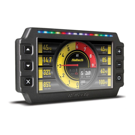
- Page 2 DISPLAY DASH OVERVIEW iC-7 DISPLAY DASH OVERVIEW The iC-7 Display Dash is available in two kits: This quick start guide will walk you through the FRONT VIEW What’s in the box? installation of a Haltech iC-7 Display Dash into Part No. HT-067010 is pre-configured for 1 Display Screen a vehicle already fitted with a Haltech ECU or • Haltech iC-7 Display Dash connection to all Haltech ECUs via a supplied equipped with an OBD-II port. 2 Control Buttons • 34 Pin main connector harness DTM-4 to DTM-4 CAN extension cable. This guide is accompanied by the Help 3 Shift / Alarm Light Panel • DTM-4 to OBD-II CAN cable Part No. HT-067012 is pre-configured for information available within the iC-7 software (with HT-067012) connection to an OBD-II port via a supplied 4 Ambient Light Sensor (iCC), located on the USB key provided.
- Page 3 DISPLAY DASH OPERATION • The channel to be displayed at each location Screen Navigation on the screen. Three keys perform the screen navigation. • The connection method. Eg. Haltech CAN or OBD-II. • Press key to go back to the previous screen in the sequence. • Shift light RPM points and colours. • Press key to go to the next screen • Alarm thresholds, colour for on-screen in the sequence. display and shift lights, manual or auto reset methods. • Press to go to the home (default) screen. When the dash is powered up it will display Installing the software a Haltech Logo Screen. After an initial 1. Insert the supplied USB Key into your PC. If configuration time the dash will display the you have lost your USB key, you can download default home screen. is always at full brightness regardless of the The colours available are red, green, blue and the Haltech iCC software directly from the You can choose from a number of display ambient light level. their combinations (yellow, cyan, magenta and “Downloads” section of the Haltech website.
- Page 4 MOUNTING OPTIONS 28mm 28mm Universal Mounting Bracket HT-060070 Bolts directly to the back of your iC-7 using three mounting screws provided. Tube Mount Through Hole HT-060072 Universal Mounting Bracket Suits tube OD 1.25in with Integrated Visor HT-060071 Designed to mount optional dash mounting brackets HT-060070 or Bolts directly to the back of your iC-7 using HT-060071 to 1.25in OD tube. three mounting screws provided. Includes a sun visor which reduces glare and protects the screen.
- Page 5 37mm 141mm 37mm M5 - Max thread depth 6mm 70mm 70mm...
- Page 6 TO HALTECH ECU INSTALLATION If you do not have any devices on your Haltech CAN bus already: 28mm 28mm Connect the DTM-4 into the Auxiliary CAN Bus Port as shown 1. Find a suitable place to mount your iC-7 Display Dash. A pull-out mechanical template is provided in the centre of this booklet if holes need to be cut in an existing panel. If you already have devices on your Haltech Through Hole CAN bus (eg Haltech wideband, TCA, I/O 2. Plug the supplied M5 (small circular expander): connector) to USB cable into the “Comms” If there is an open port at the end of the connector on the dash. CAN bus (e.g the spare DTM-4 connector 3. Plug the supplied Main Connector Harness on a Haltech WB1/WB2), connect the (34-pin Superseal connector) into the 34 pin DTM-4 to the new device into this port as shown connector on the dash labelled “Auxiliary”. 4. Plug the DTM-4 to DTM-4 CAN extension cable into the Main Connector Harness DTM-4 Otherwise, you will need to add a CAN Hub connector. (HT-159000). 5. Thread the cables through the hole in the The Elite CAN Hub features four DTM4 mounting bracket or panel.
- Page 7 GROUND connected to a switched +12V “Key On” power 2 CAN Low source in the vehicle as per the diagram (ie. connection to switched +12V supply) 3 +12V Supply Please refer to your specific ECU wiring 4 Battery Ground Rear View, Wire Side diagram for more information. Connecting iC-7 Display Dash to a Haltech Platinum Series ECU: You will need to use an 8-pin Tyco to DTM-4 cable to connect all Platinum Series ECUs to Haltech iC-7 OBD-II Dash (HT-067012) this device. This cable is supplied with the ECU. comes supplied with a 1400mm (55”) If you already have a Platinum Series ECU and are adding the iC-7 display dash to your OBD-II CAN Cable (HT-135003). system this cable can be purchased separately (HT-130040). This cable is used to connect the Haltech iC-7 to your car's OBD-II port. Connect to the OBD-II port on your vehicle...
- Page 8 AVAILABLE FUNCTIONS IN battery charger connected as this could damage the ECU and other electrical equipment. +5V SUPPLY If the Haltech product is found to be defective as mentioned above, it will be replaced or repaired AVI 4 PRESSURE SENSORS...
- Page 9 10/2020 Haltech Australia 17 Durian Place, Wetherill Park NSW 2164 Australia Phone: +61 2 9729 0999 Email: aus@haltech.com Haltech New Zealand Grey Lynn Auckland, NZ 1021 Phone: 09 887 0616 Email: nz@haltech.com Haltech USA East 750 Miles Point Way, Lexington, KY 40510 USA Phone: +1 888 298 8116 Email: usa@haltech.com...
Need help?
Do you have a question about the iC-7 and is the answer not in the manual?
Questions and answers