Table of Contents
Advertisement
Quick Links
Advertisement
Table of Contents

Related Manuals for Haltech NEXUS R3


Summary of Contents for Haltech NEXUS R3
- Page 1 QUICK START GUIDE...
- Page 2 • NEXUS R3 – a connection or series of connections Optional accessories (sold separately) What is a NEXUS R3 Vehicle Control Unit? linking two or more things. • SurLok Connectors (Red & Black) • Plug and pins set. AMP 34 pin key 1, AMP 34 pin •...
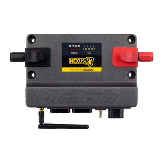
- Page 3 NEXUS R3 OVERVIEW NEXUS R3 LED BEHAVIOUR 1 2 3 4 COLOUR CONDITION 1 Power LED Power Green Normal operation (on main power or low power mode) 2 DTC LED Blue Connect to unit and install firmware 3 Wi-Fi LED 4 Datalog LED Hardware fault...
- Page 4 NEXUS R3 SPECIFICATIONS OUTPUTS COMMUNICATIONS Ignition CAN Bus Networks 1000, 500 or 250 kbit/s Injector (peak and hold) High Speed USB 2.0 (USB-C interface) 480 Mbit/s connection Digital Pulsed Outputs (DPO) Power up over USB Datalogging, settings and firmware upgrade available Power for Ignition Switch Wi-Fi 900 kB/s datalog extraction. Hardware lockout for security...
-
Page 5: Installing The Software
USB key, you can download map configuration and data-log extraction without the Haltech NSP software from the DOWNLOADS 1. Open NSP and connect to your NEXUS R3 via powering the VCU completely. VCU inputs and section of the Haltech website. -
Page 6: Mounting Template
NEXUS R3 on. Main Power and Ground Method 1: If wiring to an existing ignition key The NEXUS R3 must be connected to battery switch in the vehicle, it is important to make positive and battery negative at all times for sure to wire A13 to the main ignition wire (i.e. - Page 7 196mm 174.2mm 6.50mm...
- Page 8 NEXUS R3 WIRING Crank (Trigger) and Cam (Home) Inputs Example Wiring Connections The crank and cam position sensors are required MOUNTING TEMPLATE so that the VCU has the necessary information available to determine engine speed and position +12V (HBO5) at any point in time.
-
Page 9: Injector Outputs
NEXUS R3 WIRING Ignition Outputs 8-CYL DIRECT FIRE IGNITION 8-CYL SEQUENTIAL INJECTION The ignition outputs produce a signal between 12V and ground to control the charging and firing (WIRE AS PER CYLINDER ORDER) (WIRE AS PER CYLINDER ORDER) of an ignition coil. Ignition outputs can only be connected directly to ignition coils if the coils are equipped with internal ignitors. - Page 10 If not being used as push-pull drivers, Half Bridge GROUND THERMOFAN Specs: Outputs on the NEXUS R3 can also be used as HBO 4 generic high side or low side outputs capable of • Number of channels: 6 DBW THROTTLE 1 driving 8A to 12V, or sinking 8A to ground.
- Page 11 Specs: • -10 to +10V digital input AVIs have a software selectable 1K pull-up The NEXUS R3 VCU uses the knock sensor signal • 0 to 5V analog input resistor to 5V, which can be enabled or disabled • Number of channels: 2 SENSOR +5V to modify ignition timing if knocking occurs.
-
Page 12: Warranty Certificate
Bosch LSU 4.9 or NTK wideband sensors, battery charger connected as this could damage the ECU and other electrical equipment. If the Haltech product is found to be defective as mentioned above, it will be replaced or repaired Haltech WB1 or Haltech WB2. The diagram below which can be selected in the wideband O2 sensor •... - Page 13 03/2023 Haltech Australia Haltech USA East Haltech UK 17 Durian Place, 750 Miles Point Way, Unit 1, Miras Business Estate, Wetherill Park NSW 2164 Lexington, KY USA 40510 Keys Park Road, Hednesford, Australia Phone: (888) 298 8116 WS12 2FS Email: usa@haltech.com...
Need help?
Do you have a question about the NEXUS R3 and is the answer not in the manual?
Questions and answers