Advertisement
Quick Links
Advertisement

Related Manuals for Haltech NEXUS R5


Summary of Contents for Haltech NEXUS R5
- Page 1 QUICK START GUIDE...
- Page 2 • A high speed Wi-Fi communications module • All natively interconnected with each other • All programmable with one single piece of software The NEXUS R5 is Haltech’s new flagship product. Boasting new, innovative yet user-friendly technology, it sets a new market standard for engine management and power distribution systems.
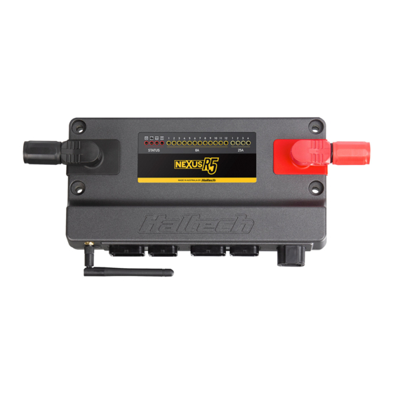
- Page 3 NEXUS R5 OVERVIEW What’s in the box? • NEXUS R5 • SurLok Connectors (Red & Black) Optional accessories (sold separately) • Wi-Fi Antenna RP-SMA 108mm • Plug and Pins Set. AMP 26 pin key 1 & 3 • Mounting Bolts and 34 pin key 1 &...
- Page 4 NEXUS R5 OVERVIEW 1 Power LED 2 DTC LED 3 Wi-Fi LED 4 Datalog LED 5 8A HCO LEDs 6 25A HCO LEDs 7 Battery Negative Stud 8 Battery Positive Stud 9 Wi-Fi Antenna (RP-SMA) 10 USB-C Port (Comms) 11 Connector A (Superseal 34-pin Keyway 1)
- Page 5 NEXUS R5 LED BEHAVIOUR COLOUR CONDITION Power Green Normal operation (on main power or low power mode) Blue Connect to unit and install firmware Hardware fault None DTCs not present Yellow A DTC is present (of any kind, past/present/not severe/severe) Blue PDM in boot mode - connect to unit and install firmware WiFi None Wi-Fi is disabled...
- Page 6 NEXUS R5 SPECIFICATIONS FEATURES FEATURES continued Drive-By-Wire Throttle Support CAN Networks Flex Fuel Nitrous Control Stage Closed Loop O2 Control Dual Bank Boost Control 4D Closed Loop Knock Control Dual CO2 Control Variable Cam Control Up to 4 Intake Air Bleed Control...
- Page 7 OUTPUTS COMMUNICATIONS Ignition CAN Bus Networks 1000, 500 or 250 kbit/s Injector (peak and hold) High Speed USB 2.0 (USB-C interface) 480 Mbit/s connection Digital Pulsed Outputs (DPO) Power up over USB Datalogging, settings and firmware upgrade available Power for Ignition Switch Wi-Fi 900 kB/s datalog extraction. Hardware lockout for security Half Bridge Outputs (HBO) 4 (2 x H-Bridges/DBW throttles) DATA LOGGING...
- Page 8 NEXUS SOFTWARE - NSP Going Online with the ECU 1. Plug the supplied USB-C cable into the USB-C Port on the front of the NEXUS R5. 2. The USB-C connection will power the ECU in Installing the software a low power mode.
- Page 9 To set up your Wi-Fi connection follow these steps: 1. Open NSP and connect to your NEXUS R5 via the supplied USB-C cable. 2. Click on Connections in the feature tree and enable the Wi-Fi module setting.
- Page 10 NEXUS R5 WIRING Main Power The NEXUS R5 must be connected to battery positive and battery negative at all times for correct operation. • Connect the NEXUS R5 to the positive battery IGNITION IGNITION SWITCH SWITCH terminal via the supplied RED SurLok connector...
- Page 11 MOUNTING TEMPLATE SurLok terminals installed...
- Page 14 MOUNTING TEMPLATE SurLok terminals installed SurLok terminals not installed...
- Page 15 Ignition Outputs Ignition outputs must be connected directly to an ignition module to control the ignition of the IGN 1 vehicle. Do not connect directly to a coil without an IGN 2 internal or external ignition module as doing DIRECT FIRE IGNITION this will damage the ECU.
- Page 16 NEXUS R5 WIRING INJ #1 INJ #2 Injection Outputs All Injectors are to be wired directly to the ECU’s corresponding cylinder output pins. INJ #3 When an injection event occurs the ECU will ground the output pin, opening the injector.
- Page 17 Digital Pulsed Outputs (DPO) HBO 1 Digital Pulsed Outputs are capable of producing pulsed waveforms with varying duty and HBO 2 frequency. When a Digital Pulsed Output is activated by the ECU the output will switch to ground. HBO 3 The pull-up voltage specifies the waveforms maximum voltage output eg 0 to 12V or 0 to 5V.
- Page 18 NEXUS R5 WIRING Example Wiring Connections Hall E ect Sensor Crank (Trigger) and Cam (Home) Inputs +12V The crank and cam position sensors are Signal Ground required so that the ECU has the necessary information available to determine engine Crank (Trigger) (+) indicates not connected speed and position at any point in time.
- Page 19 8A High Current Outputs (8A HCO) Example Wiring Connections THERMOFAN The NEXUS R5 features 12 high side outputs which are capable of driving 8A to 12V. Each output has a software programmable fuse 25A HCO current. Once the electronic fuse blows the output turns off for a software programmable delay duration, before reactivating the output.
- Page 20 NEXUS R5 WIRING SIGNAL GROUND SIGNAL GROUND Pull-up resistors are generally enabled for TEMPERATURE Analogue Voltage Inputs (AVI) temperature related sensors and switched SENSOR TEMPERATURE to ground inputs. The following configuration Analogue Voltage Inputs are inputs to the ECU SENSOR requires the pull-up resistor be enabled.
- Page 21 • -10 to 10V digital input Specs: • 0 to 5V analog input The NEXUS R5 ECU uses the knock sensor • -2.5 to 2.5V AC input only • 1 million samples per second signal to modify ignition timing if knocking •...
- Page 22 Up to Two Wideband O2 sensors can be The NEXUS R5 includes three separate CAN connected directly to the NEXUS R5 for buses. If using the Haltech CAN bus, see the monitoring purposes, or for closed loop O2 wiring information on your selected CAN device control.
- Page 23 ECU and other electrical equipment. If the Haltech product is found to be defective as mentioned above, it will be replaced or repaired if returned prepaid along with proof of purchase. Proof of purchase in the form of a copy of the Do not overcharge the battery or reverse the polarity of the battery or any charging unit.
- Page 24 06/2020 Haltech Australia 17 Durian Place, Wetherill Park NSW 2164 Australia Phone: +61 2 9729 0999 Email: aus@haltech.com Haltech New Zealand Grey Lynn Auckland, NZ 1021 Phone: 09 887 0616 Email: nz@haltech.com Haltech USA East 750 Miles Point Way, Lexington, KY 40510 USA Phone: +1 888 298 8116 Email: usa@haltech.com...
Need help?
Do you have a question about the NEXUS R5 and is the answer not in the manual?
Questions and answers