Advertisement
Quick Links
Advertisement

Related Manuals for Haltech iC-7


Summary of Contents for Haltech iC-7
- Page 1 DISPLAY DASH QUICK START GUIDE...
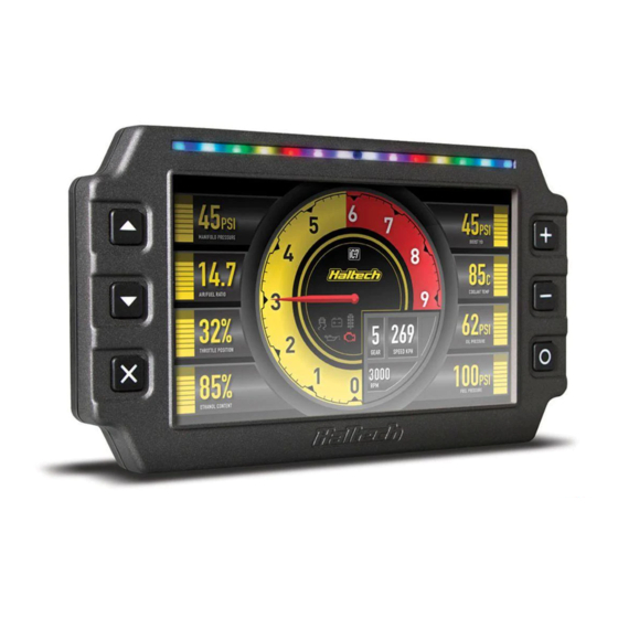
- Page 2 DISPLAY DASH OVERVIEW iC-7 DISPLAY DASH OVERVIEW The iC-7 Display Dash is available in two kits: This quick start guide will walk you through the FRONT VIEW What’s in the box? installation of a Haltech iC-7 Display Dash into Part No. HT-067010 is pre-configured for 1 Display Screen a vehicle already fitted with a Haltech ECU or • Haltech iC-7 Display Dash connection to all Haltech ECUs via a supplied equipped with an OBD-II port. 2 Control Buttons • 34 Pin main connector harness DTM-4 to DTM-4 CAN extension cable. This guide is accompanied by the Help 3 Shift / Alarm Light Panel • DTM-4 to OBD-II CAN cable Part No. HT-067012 is pre-configured for information available within the iC-7 software (with HT-067012) connection to an OBD-II port via a supplied 4 Ambient Light Sensor (iCC), located on the USB key provided.
- Page 3 DISPLAY DASH OPERATION • The channel to be displayed at each location on the screen. Screen Navigation • The connection method. Eg. Haltech CAN Three keys perform the screen navigation. or OBD-II. • Press key to go back to the previous • Shift light RPM points and colours. screen in the sequence. • Alarm thresholds, colour for on-screen • Press key to go to the next screen display and shift lights, manual or auto reset in the sequence. methods. • Press to go to the home (default) screen. Installing the software When the dash is powered up it will display 1. Insert the supplied USB Key into your PC. If a Haltech Logo Screen. After an initial you have lost your USB key, you can download configuration time the dash will display the the Haltech iCC software directly from the On the maximum brightness setting, the display The colours available are red, green, blue and default home screen. “Downloads” section of the Haltech website. is always at full brightness regardless of the their combinations (yellow, cyan, magenta and ambient light level.
- Page 4 MOUNTING OPTIONS Universal Mounting iC-7 TO HALTECH ECU INSTALLATION Bracket If you do not have any devices on your HT-060070 Haltech CAN bus already: Moulded Panel Mount Bolts directly to the Connect the DTM-4 into the Auxiliary HT-060090 back of your iC-7 using CAN Bus Port as shown 1. Find a suitable place to mount your iC-7 three mounting screws Bolts directly to the back of your iC-7 Display Dash. A pull-out mechanical template provided. using three mounting screws provided. is provided in the centre of this booklet if holes 10” x 20”, can be trimmed to fit a need to be cut in an existing panel. If you already have devices on your Haltech variety of cluster surrounds. CAN bus (eg Haltech wideband, TCA, I/O 2. Plug the supplied M5 (small circular expander): Universal Mounting Bracket connector) to USB cable into the “Comms”...
- Page 5 TO OBD-II INSTALLATION 28mm 28mm The iC-7 to OBD-II CAN Cable allows the Haltech iC-7 Dash to display the data obtained from the vehicle’s OBD-II system in real-time. FUSE This cable also provides a power source to the dash. IGNITION Through Hole SWITCH The +12V Supply from the vehicle’s OBD II connector is constant and would cause the dash to be powered even when the vehicle is off. For this reason, the RED power wire must be GROUND connected to a switched +12V “Key On” power source in the vehicle as per the diagram (ie. connection to switched +12V supply) Please refer to your specific ECU wiring diagram for more information. Haltech iC-7 OBD-II Dash (HT-067012) comes supplied with a 1400mm (55”) OBD-II CAN Cable (HT-135003). This cable is used to connect the Haltech iC-7 to your car's OBD-II port. Connect to the OBD-II port on your vehicle...
- Page 6 37mm 141mm 37mm M5 - Max thread depth 6mm 70mm 70mm...
- Page 7 Haltech CAN Supported Dash (see below) Rear View, Wire Side 5. For extended functionality of the iC-7 Display Through Hole Dash, Elite firmware 2.35 or later is required. CAN Connection: 34 pin Superseal Connector Earlier firmware versions are supported, but some channels may not display. Pin Number Connection 1 CAN High 2 CAN Low 3 +12V Supply 4 Battery Ground Rear View, Wire Side Connecting iC-7 Display Dash to a Haltech Platinum Series ECU: You will need to use an 8-pin Tyco to DTM-4 cable to connect all Platinum Series ECUs to this device. This cable is supplied with the ECU. If you already have a Platinum Series ECU and are adding the iC-7 display dash to your system this cable can be purchased separately (HT-130040).
- Page 8 Suits: Link Storm, Extreme, Fury, Thunder, Force GDI ECUs using Part No: HT-130046 1. Connect to the iC-7 with the ICC software. front circular CAN connector. Flying lead harness with pins for AMP 2. In the “Load Defaults” drop down menu select superseal connectors.
- Page 9 Speedometer Input 3. Display the Speed Pulse Rate channel Connect this input to your current tachometer iC-7 STANDALONE SETUP on an available gauge. input wire. This wire can originate from a The speed sensor provides a signal which, when factory ECU, an ignition coil or your engine 4. Drive the vehicle at 40KPH (25MPH) and note received by the iC-7 can be used to display wiring harness. the Speed Pulse Rate value. vehicle speed and/or set up speed-based The iC-7 can be used as a “Standalone” dash on This harness supports both the CAN and the Loading iC-7’s Standalone Default To configure the RPM (TACHO IN) channel in alarms. cars without a Haltech (or any aftermarket) ECU OBDII versions of the iC-7 Display Dash. You will need an external device (such as a GPS From the main screen click on the “Load the ICC software, select the tachometer on the as well as carburated or mechanically injected Speed smartphone app) to reference vehicle The Haltech iC-7 harness will connect directly This harness connects directly to Haltech’s Defaults” menu and select “Standalone”. main dash layout page. applications using the semi-terminated harness speed. to a Haltech GPS Speed Input Module (HT- iC-7 Display Dash with a 34 Pin Superseal (HT-060300).
-
Page 10: Warranty Certificate
ECU and other electrical equipment. values manually. TEMPERATURE SENSORS If the Haltech product is found to be defective as mentioned above, it will be replaced or repaired The harness also features a DTM-2 in-line Follow the steps below if you need to change if returned prepaid along with proof of purchase. Proof of purchase in the form of a copy of the Do not overcharge the battery or reverse the polarity of the battery or any charging unit. - Page 11 08/2021 Haltech Australia 17 Durian Place, Wetherill Park NSW 2164 Australia Phone: +61 2 9729 0999 Email: aus@haltech.com Haltech New Zealand Grey Lynn Auckland, NZ 1021 Phone: 09 887 0616 Email: nz@haltech.com Haltech USA East 750 Miles Point Way, Lexington, KY 40510 USA Phone: +1 888 298 8116 Email: usa@haltech.com Haltech USA West 26429 Rancho Parkway S, Unit 125 Lake Forest, CA 92630 USA Phone: +1 949 490 5660 Email: usa@haltech.com Haltech UK Unit 1, Miras Business Estate, Lower Keys Business Park, Keys Park Road, Hednesford, WS12 2FS Phone: +44 121 285 6650 Email: uk@haltech.com Haltech Europe Ottogasse 2A, 2333 Leopoldsdorf, Austria Phone: +43 720 883968 facebook.com/HaltechEngineManagement youtube.com/haltechecu...
Need help?
Do you have a question about the iC-7 and is the answer not in the manual?
Questions and answers